EP1840531A2 - Ultraschalldurchflussmessgerät - Google Patents
Ultraschalldurchflussmessgerät Download PDFInfo
- Publication number
- EP1840531A2 EP1840531A2 EP20060024861 EP06024861A EP1840531A2 EP 1840531 A2 EP1840531 A2 EP 1840531A2 EP 20060024861 EP20060024861 EP 20060024861 EP 06024861 A EP06024861 A EP 06024861A EP 1840531 A2 EP1840531 A2 EP 1840531A2
- Authority
- EP
- European Patent Office
- Prior art keywords
- intermediate plate
- ultrasonic
- ultraschalldurchflußmeßgerät
- piezoelectric element
- connecting element
- Prior art date
- Legal status (The legal status is an assumption and is not a legal conclusion. Google has not performed a legal analysis and makes no representation as to the accuracy of the status listed.)
- Granted
Links
Images


Classifications
-
- G—PHYSICS
- G01—MEASURING; TESTING
- G01F—MEASURING VOLUME, VOLUME FLOW, MASS FLOW OR LIQUID LEVEL; METERING BY VOLUME
- G01F1/00—Measuring the volume flow or mass flow of fluid or fluent solid material wherein the fluid passes through a meter in a continuous flow
- G01F1/66—Measuring the volume flow or mass flow of fluid or fluent solid material wherein the fluid passes through a meter in a continuous flow by measuring frequency, phase shift or propagation time of electromagnetic or other waves, e.g. using ultrasonic flowmeters
- G01F1/662—Constructional details
Definitions
- the invention relates to a Ultraschall microscopic flow through a medium-flowed line, with at least one ultrasonic transducer.
- Clamp-on ultrasonic flowmeters are characterized by being particularly easy to use: unlike other ultrasonic flowmeters that must be firmly integrated into existing piping systems by replacing a piece of the piping, clamp-on flowmeters can be easily accessed from the outside be placed on a suitable line section of the pipeline system. This line section, to which the clamp-on ultrasonic flowmeter is attached, thus becomes quasi the measuring line, without the need for its own separate measuring line, which must be used consuming in the pipeline system. This makes the use of clamp-on ultrasonic flowmeters simple and inexpensive.
- the invention thus provides that measures are taken to ensure that the ultrasonic transducer is not exposed to electromagnetic interference. If no electromagnetic interference can couple into the lines and components, such as electronic components, of the ultrasonic transducer, it is possible, for. B. by means of a shielded line, the signal output from a receiving ultrasonic transducer signal at least substantially free of external interference.
- the shielding device is formed by a metallic or at least metallically coated housing.
- a cable with a shield is provided for the electrical connection of the ultrasonic transducer and the shield of the cable is electrically connected to the shielding.
- the ultrasonic transducer is provided within an electromagnetic shielding device is basically usable for any Ultraschall beflußmeß réelle.
- the Ultraschall takeflußmeß réelle has an ultrasonic transducer with a piezoelectric element, a connection element for mounting the ultrasonic transducer is provided on the line, the piezoelectric element is mounted on the connecting element and between the piezoelectric element and the connecting element is provided an intermediate plate which is formed by a part of the metallic or at least metallic coated housing.
- the intermediate plate can follow different geometries. According to a preferred embodiment of the invention, however, it is provided that the top and bottom of the intermediate plate are parallel to each other. In this way, the ultrasonic signals passing through the intermediate plate are subjected to the least possible influence by the geometry of the intermediate plate.
- the piezoelectric element can be electrically connected in various ways. According to a preferred embodiment of the invention, however, it is provided that the intermediate plate serves as an electrical connection for the piezoelectric element.
- the intermediate plate with a metallic component in direct physical, electrically conductive contact with the piezoelectric element.
- the piezo element rests flat on the intermediate plate or parts of the intermediate plate.
- the invention is provided according to a preferred embodiment; that the piezoelectric element is fastened by means of the intermediate plate to the connecting element.
- the intermediate plate has at least one recess in which an adhesive layer is provided for attachment of the piezoelectric element to the connecting element.
- the piezoelectric element is adhesively bonded to the connecting element, namely by means of the adhesive layer provided in the recess of the intermediate plate.
- the thickness of the adhesive layer corresponds to the thickness of the intermediate plate.
- the transducer is provided for operation at a predetermined ultrasonic frequency and the thickness of the intermediate plate a quarter of the ultrasonic wavelength in the adhesive layer at the predetermined Ultrasonic frequency corresponds. In this way also an optimal adjustment is achieved, which ensures the lowest losses.
- an electrically conductive adhesive may be provided, so that the electrical contacting of the piezoelectric element does not necessarily have to take place via the intermediate plate.
- the intermediate plate at least on the side facing the piezoelectric element, preferably completely, is metallic.
- Such a metallic construction of the intermediate plate is also required for the above-described function of the intermediate plate as an electrical connection for the piezoelectric element.
- the electrical connection of the piezoelectric element on its opposite side of the intermediate plate may be formed in various ways. According to a preferred embodiment of the invention, however, it is provided that the piezoelectric element has on its side opposite the intermediate plate side as an electrical connection a voltage applied to the piezo-element terminal spring. For a particularly simple and reliable electrical contacting of the piezoelectric element is achieved.
- the piezoelectric element can be fixed freely on the connecting element.
- the connection element has positioning means for the piezo element.
- the connecting element has as positioning means of the connecting element projecting walls or pins, within which a precisely defined positioning location is determined for the piezoelectric element.
- connection element can be made of different materials and follow different geometries. According to a preferred embodiment of the invention, however, it is provided that a wedge, preferably made of plastic, is provided as the connecting element.
- the Ultraschallwandlerü has a connection element 1 in the form of a plastic wedge over which the actual connection of the Ultraschallwandlerü takes place to the not shown line through which the medium flows, measured the flow shall be.
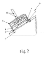
- the connection element 1 has positioning devices 2 in the form of projecting wall sections, which serve as positioning aid for a metallic intermediate plate 3 and a piezo element 4.
- the intermediate plate 3 has an opening in its inner region, so that when lying on the connecting element 1 intermediate plate 3, a space results, which can be filled with an adhesive layer 5, such. B. from Figs. 2 and 3 can be seen.
- an adhesive layer 5 such. B. from Figs. 2 and 3 can be seen.
- the adhesive layer 5 it may be z. B. be a one- or two-component electrically conductive epoxy adhesive.
- the intermediate plate 3 formed such that the piezoelectric element 4 rests not only on the adhesive layer 5, but also on parts of the intermediate plate. 3
- an electromagnetic shielding device 6 is now provided for shielding electromagnetic interference, which is composed of the intermediate plate 3 and a housing 7 made of metal.
- the housing 7 rests on the intermediate plate 3, so that there is a closed, shielded room, within which the ultrasonic transducer 8 including the piezoelectric element 4 and further electronic devices 9 are provided.
- the piezoelectric element 4 rests on the intermediate plate 3 in a galvanically conductive manner and the shield of the coaxial cable 10 is connected to the resting on the intermediate plate 3 housing 7, a grounding of the piezo-element on the terminal spring 11 opposite side.
- connection element 1 The entire components are finally protected by a plastic housing 12 which is screwed onto the connection element 1. Overall, this ensures that the output from the ultrasonic transducer 8 measurement signal can be output quasi free of external interference.
- the thickness of the adhesive layer 5 corresponds to the thickness of the intermediate plate 3.
- the Meßwandler worn is provided for operation at a predetermined ultrasonic frequency, so that the thickness of the intermediate plate 3 can be selected such that it corresponds to a quarter of the ultrasonic wavelength in the adhesive layer 5 at the predetermined ultrasonic frequency.
Landscapes
- Physics & Mathematics (AREA)
- Electromagnetism (AREA)
- Fluid Mechanics (AREA)
- General Physics & Mathematics (AREA)
- Measuring Volume Flow (AREA)
- Ultra Sonic Daignosis Equipment (AREA)
Abstract
Description
- Die Erfindung betrifft ein Ultraschalldurchflußmeßgerät, insbesondere ein Clamp-on-Ultraschalldurchflußmeßgerät, zur Messung des Durchflusses durch eine von einem Medium durchströmte Leitung, mit wenigstens einem Ultraschallwandler.
- Clamp-on-Ultraschalldurchflußmeßgeräte zeichnen sich dadurch aus, daß sie besonders einfach eingesetzt werden können: Im Gegensatz zu anderen Ultraschalldurchflußmeßgeräten, die in bestehende Rohrleitungssysteme fest integriert werden müssen, indem sie ein Stück der Rohrleitung ersetzen, können Clamp-on-Durchflußmeßgeräte einfach von außen auf einen geeigneten Leitungsabschnitt des Rohrleitungssystems aufgesetzt werden. Dieser Leitungsabschnitt, an dem das Clamp-on-Ultraschalldurchflußmeßgerät angebracht ist, wird damit quasi zur Meßleitung, ohne daß es einer eigenen separaten Meßleitung bedarf, die in das Rohrleitungssystem aufwendig eingesetzt werden muß. Dies macht die Verwendung von Clamp-on-Ultraschalldurchflußmeßgeräten einfach und kostengünstig.
- Bei Clamp-on-Ultraschalldurchflußmeßgeräten, wie auch bei anderen Ultraschalldurchflußmeßgeräten, ist jedoch häufig problematisch, daß die erzielbaren Signale nur sehr gering sind. Dies ist z. B. auf geringe Betriebsspannungen aufgrund von eigensicher ausgebildeten Stromkreisen zurückzuführen. Darüber hinaus wird das Signal-zu-Rausch-Verhältnis auch durch nicht angepaßte akustische Übergänge zwischen unterschiedlichen Materialien verschlechtert. Schließlich kommt es auch auf dem Signalweg zu Signalverlusten aufgrund von Dämpfungseffekten in dem jeweiligen Medium. Damit ist häufig ein nur sehr geringes Meßsignal verbunden, das von einem empfangenden Ultraschallwandler ausgegeben wird. Ein solches geringes Meßsignal ist nun insbesondere hinsichtlich elektromagnetischer Störungen stark anfällig.
- Damit ist es die Aufgabe der Erfindung, ein derartiges Ultraschalldurchflußmeßgerät, insbesondere ein Clamp-on-Ultraschalldurchflußmeßgerät, anzugeben, das ein gutes Signal-zu-Rausch-Verhältnis liefert.
- Ausgehend von dem eingangs beschriebenen Ultraschalldurchflußmeßgerät ist diese Aufgabe dadurch gelöst, daß der Ultraschallwandler innerhalb einer elektromagnetischen Abschirmeinrichtung vorgesehen ist.
- Erfindungsgemäß ist also vorgesehen, daß Maßnahmen getroffen werden, die gewährleisten, daß der Ultraschallwandler keinen elektromagnetischen Störungen ausgesetzt wird. Können in die Leitungen und Bauteile, wie elektronische Bauteile, des Ultraschallwandlers keine elektromagnetischen Störungen einkoppeln, so ist es möglich, z. B. mittels einer abgeschirmten Leitung, das von einem empfangenden Ultraschallwandler ausgegebene Signal zumindest im wesentlichen frei von äußeren Störungen auszukoppeln.
- Grundsätzlich sind im Rahmen der Erfindung unterschiedliche Abschirmeinrichtungen möglich. Gemäß einer bevorzugten Weiterbildung der Erfindung ist jedoch vorgesehen, daß die Abschirmeinrichtung von einem metallischen oder zumindest metallisch beschichteten Gehäuse gebildet wird. Gemäß einer bevorzugten Weiterbildung der Erfindung ist ferner vorgesehen, daß zum elektrischen Anschluß des Ultraschallwandlers ein Kabel mit einer Abschirmung vorgesehen ist und die Abschirmung des Kabels mit der Abschirmeinrichtung galvanisch leitend verbunden ist. Damit wird der zuvor schon geschilderte Vorteil erzielt, daß das von dem Ultraschallwandler ausgegebene Meßsignal quasi frei von äußeren Störungen ausgegeben werden kann.
- Die erfindungsgemäße Lösung, daß der Ultraschallwandler innerhalb einer elektromagnetischen Abschirmeinrichtung vorgesehen ist, ist grundsätzlich für jedes beliebige Ultraschalldurchflußmeßgerät verwendbar. Gemäß einer bevorzugten Weiterbildung der Erfindung ist jedoch vorgesehen, daß das Ultraschalldurchflußmeßgerät einen Ultraschallwandler mit einem Piezo-Element aufweist, ein Anschlußelement zur Anbringung des Ultraschallwandlers an der Leitung vorgesehen ist, das Piezo-Element auf dem Anschlußelement befestigt ist und zwischen dem Piezo-Element und dem Anschlußelement eine Zwischenplatte vorgesehen ist, die von einem Teil des metallischen oder zumindest metallisch beschichteten Gehäuses gebildet wird.
- Insbesondere durch das Vorsehen der in Rede stehenden Zwischenplatte lassen sich weitere Vorteile erzielen, nämlich eine optimale Anpassung des Übergangs der Ultraschallsignale von dem Piezo-Element auf das Anschlußelement durch entsprechende geometrische Ausgestaltung und Anpassung der Zwischenplatte, wie weiter unten im Detail ausgeführt.
- Grundsätzlich kann die Zwischenplatte unterschiedlichen Geometrien folgen. Gemäß einer bevorzugten Weiterbildung der Erfindung ist jedoch vorgesehen, daß die Oberseite und die Unterseite der Zwischenplatte parallel zueinander verlaufen. Auf diese Weise werden die durch die Zwischenplatte laufenden Ultraschallsignale den geringstmöglichen Beeinflussungen durch die Geometrie der Zwischenplatte unterworfen.
- Grundsätzlich kann das Piezo-Element auf verschiedene Weisen elektrisch angeschlossen sein. Gemäß einer bevorzugten Weiterbildung der Erfindung ist jedoch vorgesehen, daß die Zwischenplatte als ein elektrischer Anschluß für das Piezo-Element dient. Dazu kann die Zwischenplatte mit einem metallischen Anteil in direktem physikalischen, galvanisch leitenden Kontakt mit dem Piezo-Element stehen. Insbesondere ist in diesem Zusammenhang vorgesehen, daß das Piezo-Element plan auf der Zwischenplatte bzw. Teilen der Zwischenplatte aufliegt.
- Weiterhin ist gemäß einer bevorzugten Weiterbildung der Erfindung vorgesehen; daß das Piezo-Element mittels der Zwischenplatte an dem Anschlußelement befestigt ist. Dazu kann gemäß einer bevorzugten Weiterbildung der Erfindung vorgesehen sein, daß die Zwischenplatte wenigstens eine Ausnehmung aufweist, in der eine Klebemittelschicht zur Befestigung des Piezo-Elements an dem Anschlußelement vorgesehen ist. Das heißt mit anderen Worten, daß das Piezo-Element auf das Anschlußelement aufgeklebt ist, nämlich mittels der in der Ausnehmung der Zwischenplatte vorgesehenen Klebemittelschicht.
- Diesbezüglich ist gemäß einer bevorzugten Weiterbildung der Erfindung ferner vorgesehen, daß die Dicke der Klebemittelschicht der Dicke der Zwischenplatte entspricht. Schließlich ist gemäß einer bevorzugten Weiterbildung vorgesehen, daß der Meßwandler zum Betrieb mit einer vorbestimmten Ultraschallfrequenz vorgesehen ist und die Dicke der Zwischenplatte einem Viertel der Ultraschallwellenlänge in der Klebemittelschicht bei der vorbestimmten Ultraschallfrequenz entspricht. Auf diese Weise wird ebenfalls eine optimale Anpassung erzielt, die die geringsten Verluste gewährleistet. Für die Klebemittelschicht kann ein elektrisch leitfähiger Kleber vorgesehen sein, so daß die elektrische Kontaktierung des Piezo-Elements nicht zwingend über die Zwischenplatte erfolgen muß.
- Gemäß einer bevorzugten Weiterbildung der Erfindung ist vorgesehen, daß die Zwischenplatte zumindest auf der dem Piezo-Element zugewandten Seite, vorzugsweise vollständig, metallisch ist. Eine solche metallische Ausbildung der Zwischenplatte ist auch für die zuvor beschriebene Funktion der Zwischenplatte als elektrischer Anschluß für das Piezo-Element erforderlich.
- Der elektrische Anschluß des Piezo-Elements auf seiner der Zwischenplatte gegenüberliegenden Seite kann auf verschiedene Weisen ausgebildet sein. Gemäß einer bevorzugten Weiterbildung der Erfindung ist jedoch vorgesehen, daß das Piezo-Element auf seiner der Zwischenplatte gegenüberliegenden Seite als elektrischen Anschluß eine auf dem Piezo-Element anliegende Anschlußfeder aufweist. Damit wird eine besonders einfache und verläßliche elektrische Kontaktierung des Piezo-Elements erzielt.
- Grundsätzlich kann das Piezo-Element frei auf dem Anschlußelement befestigt sein. Gemäß einer bevorzugten Weiterbildung der Erfindung ist jedoch vorgesehen, daß das Anschlußelement Positionierungseinrichtungen für das Piezo-Element aufweist. Insbesondere kann in diesem Zusammenhang vorgesehen sein, daß das Anschlußelement als Positionierungseinrichtungen von dem Anschlußelement hervorstehende Wände oder Stifte aufweist, innerhalb derer ein genau definierter Positionierungsort für das Piezo-Element bestimmt ist.
- Schließlich kann das Anschlußelement aus unterschiedlichen Materialien gefertigt sein und unterschiedlichen Geometrien folgen. Gemäß einer bevorzugten Weiterbildung der Erfindung ist jedoch vorgesehen, daß als Anschlußelement ein, vorzugsweise aus Kunststoff gefertigter, Keil vorgesehen ist.
- Nachfolgend wird ein bevorzugtes Ausführungsbeispiel der Erfindung unter Bezugnahme auf die Zeichnung im einzelnen beschrieben. In der Zeichnung zeigt
- Fig. 1
- die gesamte Ultraschallwandlereinrichtung eines Ultraschalldurchflußmeßgeräts gemäß einem bevorzugten Ausflünmgsbeispiel der Erfindung in einer Explosionsdarstellung,
- Fig. 2
- einen ersten Schnitt der Ultraschallwandlereinrichtung des Ultraschalldurchflußmeßgeräts gemäß dem bevorzugten Ausführungsbeispiel der Erfindung und
- Fig. 3
- einen zweiten Schnitt der Ultraschallwandlereinrichtung des Ultraschalldurchflußrneßgeräts gemäß dem bevorzugten Ausführungsbeispiel der Erfindung.
- Im folgenden wird für ein Ultraschalldurchflußmeßgerät gemäß einem bevorzugten Ausführungsbeispiel der Erfindung der vorliegend relevante Teil, nämlich die gesamte Ultraschallwandlereinrichtung einschließlich Anschlußelement und Gehäuse beschrieben.
- Alle Bestandteile dieser Ultraschallwandlereinheit sind aus der Explosionsdarstellung in Fig. 3 ersichtlich: Die Ultraschallwandlereinheit weist ein Anschlußelement 1 in Form eines Kunststoffkeils auf, über den der eigentliche Anschluß der Ultraschallwandlereinheit an die nicht weiter dargestellte Leitung erfolgt, durch die das Medium strömt, dessen Durchfluß gemessen werden soll. Das Anschlußelement 1 weist Positionierungseinrichtungen 2 in Form von hervorstehenden Wandabschnitten auf, die als Positionierungshilfe für eine metallische Zwischenplatte 3 und ein Piezo-Element 4 dienen.
- Die Zwischenplatte 3 weist in ihrem Innenbereich eine Öffnung auf, so daß bei auf dem Anschlußelement 1 aufliegender Zwischenplatte 3 sich ein Raum ergibt, der mit einer Klebemittelschicht 5 gefüllt werden kann, wie z. B. aus den Fig. 2 und 3 ersichtlich. Bei der Klebemittelschicht 5 kann es sich z. B. um einen ein- oder zweikomponentigen elektrisch leitfähigen Epoxidkleber handeln. Wie insbesondere auch aus den Fig. 2 und 3 ersichtlich, ist die Zwischenplatte 3 derart ausgebildet, daß das Piezo-Element 4 nicht nur auf der Klebemittelschicht 5 aufliegt, sondern auch auf Teilen der Zwischenplatte 3.
- Bei dem vorliegend beschriebenen bevorzugten Ausführungsbeispiel der Erfindung ist nun zur Abschirmung von elektromagnetischen Störungen eine elektromagnetische Abschirmeinrichtung 6 vorgesehen, die sich zusammensetzt aus der Zwischenplatte 3 und einem Gehäuse 7 aus Metall. Das Gehäuse 7 liegt auf der Zwischenplatte 3 auf, so daß sich ein geschlossener, abgeschirmter Raum ergibt, innerhalb dessen der Ultraschallwandler 8 einschließlich des Piezo-Elements 4 sowie weitere elektronische Einrichtungen 9 vorgesehen sind.
- Für den elektrischen Anschluß des Piezo-Elements 4 ist nun folgendes vorgesehen: Der elektrische Anschluß der Ultraschallwandlereinheit erfolgt über ein Koaxialkabel 10 dessen Abschirmung mit der elektromagnetischen Abschirmeinrichtung 6, nämlich dem Gehäuse 7 verbunden ist, und dessen Seele auf eine Anschlußfeder 11 geführt ist, die auf der der Zwischenplatte 3 gegenüberliegenden Seite des Piezo-Elements 4 vorgesehen ist. Dadurch, daß das Piezo-Element 4 auf der Zwischenplatte 3 in galvanisch leitender Weise aufliegt und die Abschirmung des Koaxialkabels 10 mit dem auf der Zwischenplatte 3 aufliegendem Gehäuse 7 verbunden ist, erfolgt eine Erdung des Piezo-Elements auf der der Anschlußfeder 11 gegenüberliegenden Seite.
- Geschützt werden die gesamten Bauteile schließlich durch ein Plastikgehäuse 12, das auf das Anschlußelement 1 aufgeschraubt wird. Insgesamt wird damit erreicht, daß das von dem Ultraschallwandler 8 ausgegebene Meßsignal quasi frei von äußeren Störungen ausgegeben werden kann.
- Wesentlich ist dabei auch, daß die Dicke der Klebemittelschicht 5 der Dicke der Zwischenplatte 3 entspricht. Dabei ist die Meßwandlereinrichtung zum Betrieb mit einer vorbestimmten Ultraschallfrequenz vorgesehen, so daß die Dicke der Zwischenplatte 3 derart gewählt werden kann, daß sie einem Viertel der Ultraschallwellenlänge in der Klebemittelschicht 5 bei der vorbestimmten Ultraschallfrequenz entspricht. Damit wird der Vorteil einer optimalen Anpassung des Übergangs der Ultraschallsignale von dem Piezo-Element 4 auf das Anschlußelement 11 erzielt.
Claims (14)
- Ultraschalldurchflußmeßgerät, insbesondere Clamp-on-Ultraschalldurchflußmeßgerät, zur Messung des Durchflusses durch eine von einem Medium durchströmte Leitung, mit wenigstens einem Ultraschallwandler (8), dadurch gekennzeichnet, daß der Ultraschallwandler (8) innerhalb einer elektromagnetischen Abschirmeinrichtung (6) vorgesehen ist.
- Ultraschalldurchflußmeßgerät nach Anspruch 1, dadurch gekennzeichnet, daß die elektromagnetische Abschirmeinrichtung (6) von einem metallischen oder zumindest metallisch beschichteten Gehäuse (7) gebildet wird.
- Ultraschalldurchflußmeßgerät nach Anspruch 1 oder 2, dadurch gekennzeichnet, daß zum elektrischen Anschluß des Ultraschallwandlers (8) ein Kabel (10) mit einer Abschirmung vorgesehen ist und die Abschirmung des Kabels (10) mit der elektromagnetischen Abschirmeinrichtung (6) galvanisch leitend verbunden ist.
- Ultraschalldurchflußmeßgerät nach einem der Ansprüche 1 bis 3, dadurch gekennzeichnet, daß der Ultraschallwandler (8) ein Piezo-Element (4) aufweist, ein Anschlußelement (1) zur Anbringung des Ultraschallwandlers (8) an der Leitung vorgesehen ist, das Piezo-Element (4) auf dem Anschlußelement (1) befestigt ist und zwischen dem Piezo-Element (4) und dem Anschlußelement (1) eine Zwischenplatte (3) vorgesehen ist, die von einem Teil des metallischen oder metallisch beschichteten Gehäuses (7) gebildet wird.
- Ultraschalldurchflußmeßgerät nach Anspruch 4, dadurch gekennzeichnet, daß die Oberseite und die Unterseite der Zwischenplatte (3) parallel zueinander verlaufen.
- Ultraschalldurchflußmeßgerät nach Anspruch 4 oder 5, dadurch gekennzeichnet, daß die Zwischenplatte (3) als ein elektrischer Anschluß für das Piezo-Element (4) dient.
- Ultraschalldurchflußmeßgerät nach einem der Ansprüche 4 bis 6, dadurch gekennzeichnet, daß das Piezo-Element (4) mittels der Zwischenplatte (3) an dem Anschlußelement (1) befestigt ist.
- Ultraschalldurchflußmeßgerät nach einem der Ansprüche 4 bis 7, dadurch gekennzeichnet, daß die Zwischenplatte (3) wenigstens eine Ausnehmung aufweist, in der eine Klebemittelschicht (5) zur Befestigung des Piezo-Elements (4) an dem Anschlußelement (1) vorgesehen ist.
- Ultraschalldurchflußmeßgerät nach Anspruch 8, dadurch gekennzeichnet, daß die Dicke der Klebemittelschicht (5) der Dicke der Zwischenplatte (3) entspricht.
- Ultraschalldurchflußmeßgerät nach Anspruch 9, dadurch gekennzeichnet, daß der Meßwandler (8) zum Betrieb mit einer vorbestimmten Ultraschallfrequenz vorgesehen ist und die Dicke der Zwischenplatte (3) einem Viertel der Ultraschallwellenlänge in der Klebeschicht (5) bei der vorbestimmten Ultraschallfrequenz entspricht.
- Ultraschalldurchfhißmeßgerät nach einem der Ansprüche 4 bis 10, dadurch gekennzeichnet, daß die Zwischenplatte (3) zumindest auf der dem Piezo-Eleznent (4) zugewandten Seite, vorzugsweise vollständig, metallisch ist.
- Ultraschalldurchflußmeßgerät nach einem der Ansprüche 4 bis 11, dadurch gekennzeichnet, daß das Piezo-Element (4) auf seiner der Zwischenplatte (3) gegenüberliegenden Seite als elektrischen Anschluß eine auf dem Piezo-Element (4) anliegende Anschlußfeder (11) aufweist.
- Ultraschalldurchflußmeßgerät nach einem der Ansprüche 4 bis 12, dadurch gekennzeichnet, daß das Anschlußelement (1) Positionierungseinrichtungen (2) für das Piezo-Element (4) aufweist.
- Ultraschalldurchflußmeßgerät nach einem der Ansprüche 4 bis 13, dadurch gekennzeichnet, daß als Anschlußelement (1) ein, vorzugsweise aus Kunststoff gefertigter, Keil vorgesehen ist.
Applications Claiming Priority (1)
| Application Number | Priority Date | Filing Date | Title |
|---|---|---|---|
| DE200610015218 DE102006015218B4 (de) | 2006-03-30 | 2006-03-30 | Ultraschalldurchflußmeßgerät |
Publications (3)
| Publication Number | Publication Date |
|---|---|
| EP1840531A2 true EP1840531A2 (de) | 2007-10-03 |
| EP1840531A3 EP1840531A3 (de) | 2009-01-21 |
| EP1840531B1 EP1840531B1 (de) | 2015-11-11 |
Family
ID=38294257
Family Applications (2)
| Application Number | Title | Priority Date | Filing Date |
|---|---|---|---|
| EP06024861.4A Active EP1840531B1 (de) | 2006-03-30 | 2006-12-01 | Ultraschalldurchflussmessgerät |
| EP06024860.6A Active EP1840530B1 (de) | 2006-03-30 | 2006-12-01 | Ultraschalldurchflussmessgerät |
Family Applications After (1)
| Application Number | Title | Priority Date | Filing Date |
|---|---|---|---|
| EP06024860.6A Active EP1840530B1 (de) | 2006-03-30 | 2006-12-01 | Ultraschalldurchflussmessgerät |
Country Status (5)
| Country | Link |
|---|---|
| US (2) | US7701118B2 (de) |
| EP (2) | EP1840531B1 (de) |
| JP (2) | JP2007271613A (de) |
| DE (1) | DE102006062706B4 (de) |
| NO (2) | NO20065752L (de) |
Families Citing this family (13)
| Publication number | Priority date | Publication date | Assignee | Title |
|---|---|---|---|---|
| DE102007039016A1 (de) * | 2007-08-17 | 2009-02-19 | Endress + Hauser Flowtec Ag | Koppelelement für ein Ultraschall-Durchflussmessgerät |
| DE102007060989A1 (de) | 2007-12-14 | 2009-06-18 | Endress + Hauser Flowtec Ag | Ultraschallwandler zur Bestimmung und/oder Überwachung eines Durchflusses eines Messmediums durch ein Messrohr |
| DE102008055167A1 (de) * | 2008-12-29 | 2010-07-01 | Endress + Hauser Flowtec Ag | Messsystem zur Bestimmung und/oder Überwachung des Durchflusses eines Messmediums durch das Messrohr mittels Ultraschall |
| EP2562517A1 (de) * | 2011-08-22 | 2013-02-27 | Kamstrup A/S | Ultraschall-Durchflussmesser mit einem am Strömungskanal haftenden Wandler |
| DE102011082615A1 (de) * | 2011-09-13 | 2013-03-14 | Endress + Hauser Flowtec Ag | Ultraschallwandler eines Ultraschall-Durchflussmessgeräts |
| DE102011090079A1 (de) * | 2011-12-29 | 2013-07-04 | Endress + Hauser Flowtec Ag | Ultraschallwandler für ein Ultraschall-Durchflussmessgerät |
| DE102012108254A1 (de) * | 2012-09-05 | 2014-03-06 | systec Controls Meß- und Regeltechnik GmbH | Ultraschall-Wandler und Verfahren zur Herstellung eines Ultraschall-Wandlers |
| DE102013104544B4 (de) | 2013-05-03 | 2015-03-12 | Endress + Hauser Flowtec Ag | Ultraschallwandler und Ultraschall-Durchflussmessgerät |
| US11079506B2 (en) | 2016-12-16 | 2021-08-03 | Pgs Geophysical As | Multicomponent streamer |
| USD851524S1 (en) | 2018-01-18 | 2019-06-18 | Norgas Metering Technologies, Inc. | Ultrasonic flow meter |
| JP6948968B2 (ja) * | 2018-03-14 | 2021-10-13 | 株式会社キーエンス | クランプオン式超音波流量センサ |
| DE102018126613B4 (de) * | 2018-10-25 | 2022-08-11 | Sensus Spectrum Llc | Messvorrichtung zur Bestimmung des Durchflusses eines durch einen Rohrabschnitt hindurchströmenden Fluids |
| US12399054B1 (en) | 2022-11-14 | 2025-08-26 | Sunsonic, LLC | Clamp on ultrasonic flow meter |
Citations (4)
| Publication number | Priority date | Publication date | Assignee | Title |
|---|---|---|---|---|
| US4297607A (en) | 1980-04-25 | 1981-10-27 | Panametrics, Inc. | Sealed, matched piezoelectric transducer |
| DE4124692A1 (de) | 1991-07-22 | 1993-01-28 | Flexim Flexible Industriemesst | Ultraschallmesskopf |
| DE10216037A1 (de) | 2002-04-11 | 2003-10-23 | Endress & Hauser Gmbh & Co Kg | Schall-oder Ultraschallsensor |
| EP1477778A1 (de) | 2002-01-28 | 2004-11-17 | Matsushita Electric Industrial Co., Ltd. | Akustische anpassungsschicht, ultraschallsender/-empfänger und ultraschallströmungsmesser |
Family Cites Families (24)
| Publication number | Priority date | Publication date | Assignee | Title |
|---|---|---|---|---|
| JPS5467981U (de) * | 1977-10-14 | 1979-05-14 | ||
| JPS5467981A (en) * | 1977-11-08 | 1979-05-31 | Tokyu Co Ltd | Method of and apparatus for loading or unloading and conveying work for hanger type shot blasting |
| US4240002A (en) * | 1979-04-02 | 1980-12-16 | Motorola, Inc. | Piezoelectric transducer arrangement with integral terminals and housing |
| US4373401A (en) * | 1980-05-05 | 1983-02-15 | Joseph Baumoel | Transducer structure and mounting arrangement for transducer structure for clamp-on ultrasonic flowmeters |
| JPS60141518A (ja) * | 1983-12-29 | 1985-07-26 | Matsushita Electric Ind Co Ltd | レンズ成形方法 |
| JPS60141518U (ja) * | 1984-02-29 | 1985-09-19 | 横河電機株式会社 | 超音波送受波器 |
| IT1182209B (it) * | 1985-02-18 | 1987-09-30 | Fidia Farmaceutici | Uso terapeutico del monosialoganglioside gm1 e dei suoi derivati in gravi patologie di infarti cerebrali |
| FR2598498B1 (fr) | 1985-03-15 | 1990-01-05 | Framatome Sa | Capteur pour ondes ultrasonores destine a venir en contact avec une paroi a haute temperature et application de ce capteur |
| JPS61189223U (de) * | 1985-05-16 | 1986-11-26 | ||
| JPS63188524A (ja) * | 1987-01-29 | 1988-08-04 | Daihatsu Motor Co Ltd | 4輪駆動車の切換制御装置 |
| JPS63188524U (de) * | 1987-05-28 | 1988-12-02 | ||
| DE29623089U1 (de) * | 1996-05-23 | 1997-12-11 | Siemens AG, 80333 München | Piezoelektrisches Element |
| DE29611678U1 (de) * | 1996-07-04 | 1997-08-07 | Siemens AG, 80333 München | Schallwandler, insbesondere Ultraschallwandler |
| US5866820A (en) * | 1996-09-20 | 1999-02-02 | Camplin; Kenneth R. | Coil volumetric and surface defect detection system |
| JPH10123235A (ja) * | 1996-10-15 | 1998-05-15 | Denso Corp | 超音波センサ及び車両用障害物検出装置 |
| JP3518268B2 (ja) * | 1997-08-20 | 2004-04-12 | 松下電器産業株式会社 | 超音波流量計 |
| JP2001224590A (ja) * | 2000-02-15 | 2001-08-21 | Matsushita Electric Ind Co Ltd | 超音波探触子 |
| JP3611796B2 (ja) * | 2001-02-28 | 2005-01-19 | 松下電器産業株式会社 | 超音波送受波器、超音波送受波器の製造方法及び超音波流量計 |
| JP2002365106A (ja) * | 2001-04-02 | 2002-12-18 | Kazumasa Onishi | 流量測定装置及びクランプオン型超音波流量計 |
| JP2003075219A (ja) * | 2001-09-06 | 2003-03-12 | Kazumasa Onishi | クランプオン型超音波流量計 |
| WO2003032678A2 (en) * | 2001-10-09 | 2003-04-17 | Frank Joseph Pompei | Ultrasonic transducer for parametric array |
| WO2004057913A1 (ja) * | 2002-12-20 | 2004-07-08 | Matsushita Electric Industrial Co., Ltd. | 超音波送受波器およびその製造方法、ならびに超音波流量計 |
| JP2004325169A (ja) * | 2003-04-23 | 2004-11-18 | Matsushita Electric Ind Co Ltd | 流体の流れ計測装置 |
| US6895825B1 (en) * | 2004-01-29 | 2005-05-24 | The Boeing Company | Ultrasonic transducer assembly for monitoring a fluid flowing through a duct |
-
2006
- 2006-03-30 DE DE102006062706A patent/DE102006062706B4/de not_active Expired - Lifetime
- 2006-12-01 EP EP06024861.4A patent/EP1840531B1/de active Active
- 2006-12-01 EP EP06024860.6A patent/EP1840530B1/de active Active
- 2006-12-12 NO NO20065752A patent/NO20065752L/no not_active Application Discontinuation
- 2006-12-12 NO NO20065751A patent/NO20065751L/no not_active Application Discontinuation
-
2007
- 2007-03-12 US US11/684,971 patent/US7701118B2/en active Active
- 2007-03-12 US US11/684,960 patent/US7380469B2/en active Active
- 2007-03-15 JP JP2007066885A patent/JP2007271613A/ja active Pending
- 2007-03-23 JP JP2007076042A patent/JP5108348B2/ja not_active Expired - Fee Related
Patent Citations (4)
| Publication number | Priority date | Publication date | Assignee | Title |
|---|---|---|---|---|
| US4297607A (en) | 1980-04-25 | 1981-10-27 | Panametrics, Inc. | Sealed, matched piezoelectric transducer |
| DE4124692A1 (de) | 1991-07-22 | 1993-01-28 | Flexim Flexible Industriemesst | Ultraschallmesskopf |
| EP1477778A1 (de) | 2002-01-28 | 2004-11-17 | Matsushita Electric Industrial Co., Ltd. | Akustische anpassungsschicht, ultraschallsender/-empfänger und ultraschallströmungsmesser |
| DE10216037A1 (de) | 2002-04-11 | 2003-10-23 | Endress & Hauser Gmbh & Co Kg | Schall-oder Ultraschallsensor |
Also Published As
| Publication number | Publication date |
|---|---|
| EP1840531A3 (de) | 2009-01-21 |
| US7701118B2 (en) | 2010-04-20 |
| NO20065752L (no) | 2007-10-01 |
| DE102006062706B4 (de) | 2012-12-06 |
| US20070227261A1 (en) | 2007-10-04 |
| JP5108348B2 (ja) | 2012-12-26 |
| JP2007271613A (ja) | 2007-10-18 |
| US20070227262A1 (en) | 2007-10-04 |
| NO20065751L (no) | 2007-10-01 |
| EP1840530A3 (de) | 2009-01-28 |
| EP1840530B1 (de) | 2016-03-09 |
| JP2007271615A (ja) | 2007-10-18 |
| DE102006062706A1 (de) | 2007-10-11 |
| US7380469B2 (en) | 2008-06-03 |
| EP1840530A2 (de) | 2007-10-03 |
| EP1840531B1 (de) | 2015-11-11 |
Similar Documents
| Publication | Publication Date | Title |
|---|---|---|
| US7380469B2 (en) | Ultrasonic flow rate measuring device | |
| WO2009121530A1 (de) | Füllstandschalter und sensorelement für einen füllstandschalter | |
| DE102019110256A1 (de) | TDR-Messvorrichtung zur Bestimmung der Dielektrizitätskonstanten | |
| DE19935515A1 (de) | Vorrichtung zur Messung des Anpreßdruckes eines Wicklungspreßelements in einem Leistungstransformator | |
| DE29611678U1 (de) | Schallwandler, insbesondere Ultraschallwandler | |
| EP2893303A1 (de) | Ultraschallwandler und verfahren zur herstellung eines ultraschall-wandlers | |
| DE102007029563B4 (de) | Magnetisch induktives Durchflussmessgerät | |
| EP2179253B1 (de) | Koppelelement für ein ultraschall-durchflussmessgerät | |
| DE29509574U1 (de) | Schallwandler | |
| EP1687594B1 (de) | Ultraschall-durchflussmessvorrichtung | |
| DE102019134806A1 (de) | Messrohranordnung, Messrohrsystem und Trägereinheit eines Messgerätes zum Erfassen eines Massedurchflusses, einer Viskosität, einer Dichte und/oder einer davon abgeleiteten Größe eines fließfähigen Mediums | |
| DE102006015218B4 (de) | Ultraschalldurchflußmeßgerät | |
| EP1407234B1 (de) | Messkopf für ein ultraschall-durchflussmessgerät | |
| EP3444573B1 (de) | Schallkopf für einen durchflussmesser mit ausziehmitteln | |
| DE102021127942B4 (de) | Temperatursensor und Durchflussmessgerät | |
| DE102020122803A1 (de) | Messgerät | |
| DE102018009754B4 (de) | Messeinrichtung zur Ermittlung einer Fluidgröße | |
| DE102017116027A1 (de) | Messgerät zur kapazitiven Messung eines Dielektrizitätswertes | |
| EP1504256A1 (de) | Sensor auf der basis von oberflachenwellen-bauelementen mit kapazitiver kopplung der hochfrequenzanschlüsse | |
| EP3870938B1 (de) | Magnetisch-induktives durchflussmessgerät | |
| DE102020123311A1 (de) | Ultraschall-Messgerät und Verwendung eines Ultraschall-Messgeräts | |
| DE102007058578A1 (de) | Magnetisch-induktiver Durchflussmesser | |
| DE102022133715A1 (de) | Modulares Coriolis-Durchflussmessgerät | |
| EP3454019A1 (de) | Schallkopf für einen durchflussmesser mit verstärkungsblech | |
| DE102016101154A1 (de) | Ultraschallwandler |
Legal Events
| Date | Code | Title | Description |
|---|---|---|---|
| PUAI | Public reference made under article 153(3) epc to a published international application that has entered the european phase |
Free format text: ORIGINAL CODE: 0009012 |
|
| AK | Designated contracting states |
Kind code of ref document: A2 Designated state(s): AT BE BG CH CY CZ DE DK EE ES FI FR GB GR HU IE IS IT LI LT LU LV MC NL PL PT RO SE SI SK TR |
|
| AX | Request for extension of the european patent |
Extension state: AL BA HR MK YU |
|
| PUAL | Search report despatched |
Free format text: ORIGINAL CODE: 0009013 |
|
| AK | Designated contracting states |
Kind code of ref document: A3 Designated state(s): AT BE BG CH CY CZ DE DK EE ES FI FR GB GR HU IE IS IT LI LT LU LV MC NL PL PT RO SE SI SK TR |
|
| AX | Request for extension of the european patent |
Extension state: AL BA HR MK RS |
|
| 17P | Request for examination filed |
Effective date: 20090710 |
|
| 17Q | First examination report despatched |
Effective date: 20090814 |
|
| AKX | Designation fees paid |
Designated state(s): AT BE BG CH CY CZ DE DK EE ES FI FR GB GR HU IE IS IT LI LT LU LV MC NL PL PT RO SE SI SK TR |
|
| GRAP | Despatch of communication of intention to grant a patent |
Free format text: ORIGINAL CODE: EPIDOSNIGR1 |
|
| INTG | Intention to grant announced |
Effective date: 20150522 |
|
| GRAS | Grant fee paid |
Free format text: ORIGINAL CODE: EPIDOSNIGR3 |
|
| GRAA | (expected) grant |
Free format text: ORIGINAL CODE: 0009210 |
|
| AK | Designated contracting states |
Kind code of ref document: B1 Designated state(s): AT BE BG CH CY CZ DE DK EE ES FI FR GB GR HU IE IS IT LI LT LU LV MC NL PL PT RO SE SI SK TR |
|
| REG | Reference to a national code |
Ref country code: GB Ref legal event code: FG4D Free format text: NOT ENGLISH |
|
| REG | Reference to a national code |
Ref country code: CH Ref legal event code: EP |
|
| REG | Reference to a national code |
Ref country code: IE Ref legal event code: FG4D Free format text: LANGUAGE OF EP DOCUMENT: GERMAN |
|
| REG | Reference to a national code |
Ref country code: AT Ref legal event code: REF Ref document number: 760687 Country of ref document: AT Kind code of ref document: T Effective date: 20151215 |
|
| REG | Reference to a national code |
Ref country code: DE Ref legal event code: R096 Ref document number: 502006014630 Country of ref document: DE |
|
| REG | Reference to a national code |
Ref country code: LT Ref legal event code: MG4D |
|
| REG | Reference to a national code |
Ref country code: NL Ref legal event code: MP Effective date: 20160211 |
|
| PG25 | Lapsed in a contracting state [announced via postgrant information from national office to epo] |
Ref country code: IT Free format text: LAPSE BECAUSE OF FAILURE TO SUBMIT A TRANSLATION OF THE DESCRIPTION OR TO PAY THE FEE WITHIN THE PRESCRIBED TIME-LIMIT Effective date: 20151111 Ref country code: LT Free format text: LAPSE BECAUSE OF FAILURE TO SUBMIT A TRANSLATION OF THE DESCRIPTION OR TO PAY THE FEE WITHIN THE PRESCRIBED TIME-LIMIT Effective date: 20151111 Ref country code: IS Free format text: LAPSE BECAUSE OF FAILURE TO SUBMIT A TRANSLATION OF THE DESCRIPTION OR TO PAY THE FEE WITHIN THE PRESCRIBED TIME-LIMIT Effective date: 20160311 Ref country code: NL Free format text: LAPSE BECAUSE OF FAILURE TO SUBMIT A TRANSLATION OF THE DESCRIPTION OR TO PAY THE FEE WITHIN THE PRESCRIBED TIME-LIMIT Effective date: 20151111 Ref country code: ES Free format text: LAPSE BECAUSE OF FAILURE TO SUBMIT A TRANSLATION OF THE DESCRIPTION OR TO PAY THE FEE WITHIN THE PRESCRIBED TIME-LIMIT Effective date: 20151111 |
|
| PG25 | Lapsed in a contracting state [announced via postgrant information from national office to epo] |
Ref country code: PT Free format text: LAPSE BECAUSE OF FAILURE TO SUBMIT A TRANSLATION OF THE DESCRIPTION OR TO PAY THE FEE WITHIN THE PRESCRIBED TIME-LIMIT Effective date: 20160311 Ref country code: FI Free format text: LAPSE BECAUSE OF FAILURE TO SUBMIT A TRANSLATION OF THE DESCRIPTION OR TO PAY THE FEE WITHIN THE PRESCRIBED TIME-LIMIT Effective date: 20151111 Ref country code: GR Free format text: LAPSE BECAUSE OF FAILURE TO SUBMIT A TRANSLATION OF THE DESCRIPTION OR TO PAY THE FEE WITHIN THE PRESCRIBED TIME-LIMIT Effective date: 20160212 Ref country code: SE Free format text: LAPSE BECAUSE OF FAILURE TO SUBMIT A TRANSLATION OF THE DESCRIPTION OR TO PAY THE FEE WITHIN THE PRESCRIBED TIME-LIMIT Effective date: 20151111 Ref country code: LV Free format text: LAPSE BECAUSE OF FAILURE TO SUBMIT A TRANSLATION OF THE DESCRIPTION OR TO PAY THE FEE WITHIN THE PRESCRIBED TIME-LIMIT Effective date: 20151111 Ref country code: BE Free format text: LAPSE BECAUSE OF NON-PAYMENT OF DUE FEES Effective date: 20151231 Ref country code: PL Free format text: LAPSE BECAUSE OF FAILURE TO SUBMIT A TRANSLATION OF THE DESCRIPTION OR TO PAY THE FEE WITHIN THE PRESCRIBED TIME-LIMIT Effective date: 20151111 |
|
| PG25 | Lapsed in a contracting state [announced via postgrant information from national office to epo] |
Ref country code: CZ Free format text: LAPSE BECAUSE OF FAILURE TO SUBMIT A TRANSLATION OF THE DESCRIPTION OR TO PAY THE FEE WITHIN THE PRESCRIBED TIME-LIMIT Effective date: 20151111 |
|
| REG | Reference to a national code |
Ref country code: CH Ref legal event code: PL |
|
| REG | Reference to a national code |
Ref country code: DE Ref legal event code: R097 Ref document number: 502006014630 Country of ref document: DE |
|
| PG25 | Lapsed in a contracting state [announced via postgrant information from national office to epo] |
Ref country code: EE Free format text: LAPSE BECAUSE OF FAILURE TO SUBMIT A TRANSLATION OF THE DESCRIPTION OR TO PAY THE FEE WITHIN THE PRESCRIBED TIME-LIMIT Effective date: 20151111 Ref country code: DK Free format text: LAPSE BECAUSE OF FAILURE TO SUBMIT A TRANSLATION OF THE DESCRIPTION OR TO PAY THE FEE WITHIN THE PRESCRIBED TIME-LIMIT Effective date: 20151111 Ref country code: SK Free format text: LAPSE BECAUSE OF FAILURE TO SUBMIT A TRANSLATION OF THE DESCRIPTION OR TO PAY THE FEE WITHIN THE PRESCRIBED TIME-LIMIT Effective date: 20151111 Ref country code: RO Free format text: LAPSE BECAUSE OF FAILURE TO SUBMIT A TRANSLATION OF THE DESCRIPTION OR TO PAY THE FEE WITHIN THE PRESCRIBED TIME-LIMIT Effective date: 20151111 |
|
| PLBE | No opposition filed within time limit |
Free format text: ORIGINAL CODE: 0009261 |
|
| STAA | Information on the status of an ep patent application or granted ep patent |
Free format text: STATUS: NO OPPOSITION FILED WITHIN TIME LIMIT |
|
| REG | Reference to a national code |
Ref country code: IE Ref legal event code: MM4A |
|
| PG25 | Lapsed in a contracting state [announced via postgrant information from national office to epo] |
Ref country code: MC Free format text: LAPSE BECAUSE OF FAILURE TO SUBMIT A TRANSLATION OF THE DESCRIPTION OR TO PAY THE FEE WITHIN THE PRESCRIBED TIME-LIMIT Effective date: 20151111 |
|
| REG | Reference to a national code |
Ref country code: FR Ref legal event code: ST Effective date: 20160831 |
|
| 26N | No opposition filed |
Effective date: 20160812 |
|
| GBPC | Gb: european patent ceased through non-payment of renewal fee |
Effective date: 20160211 |
|
| PG25 | Lapsed in a contracting state [announced via postgrant information from national office to epo] |
Ref country code: CH Free format text: LAPSE BECAUSE OF NON-PAYMENT OF DUE FEES Effective date: 20151231 Ref country code: IE Free format text: LAPSE BECAUSE OF NON-PAYMENT OF DUE FEES Effective date: 20151201 Ref country code: LI Free format text: LAPSE BECAUSE OF NON-PAYMENT OF DUE FEES Effective date: 20151231 |
|
| PG25 | Lapsed in a contracting state [announced via postgrant information from national office to epo] |
Ref country code: FR Free format text: LAPSE BECAUSE OF NON-PAYMENT OF DUE FEES Effective date: 20160111 Ref country code: SI Free format text: LAPSE BECAUSE OF FAILURE TO SUBMIT A TRANSLATION OF THE DESCRIPTION OR TO PAY THE FEE WITHIN THE PRESCRIBED TIME-LIMIT Effective date: 20151111 |
|
| PG25 | Lapsed in a contracting state [announced via postgrant information from national office to epo] |
Ref country code: GB Free format text: LAPSE BECAUSE OF NON-PAYMENT OF DUE FEES Effective date: 20160211 |
|
| REG | Reference to a national code |
Ref country code: AT Ref legal event code: MM01 Ref document number: 760687 Country of ref document: AT Kind code of ref document: T Effective date: 20151201 |
|
| PG25 | Lapsed in a contracting state [announced via postgrant information from national office to epo] |
Ref country code: AT Free format text: LAPSE BECAUSE OF NON-PAYMENT OF DUE FEES Effective date: 20151201 Ref country code: BG Free format text: LAPSE BECAUSE OF FAILURE TO SUBMIT A TRANSLATION OF THE DESCRIPTION OR TO PAY THE FEE WITHIN THE PRESCRIBED TIME-LIMIT Effective date: 20151111 Ref country code: HU Free format text: LAPSE BECAUSE OF FAILURE TO SUBMIT A TRANSLATION OF THE DESCRIPTION OR TO PAY THE FEE WITHIN THE PRESCRIBED TIME-LIMIT; INVALID AB INITIO Effective date: 20061201 |
|
| PG25 | Lapsed in a contracting state [announced via postgrant information from national office to epo] |
Ref country code: CY Free format text: LAPSE BECAUSE OF FAILURE TO SUBMIT A TRANSLATION OF THE DESCRIPTION OR TO PAY THE FEE WITHIN THE PRESCRIBED TIME-LIMIT Effective date: 20151111 |
|
| PG25 | Lapsed in a contracting state [announced via postgrant information from national office to epo] |
Ref country code: TR Free format text: LAPSE BECAUSE OF FAILURE TO SUBMIT A TRANSLATION OF THE DESCRIPTION OR TO PAY THE FEE WITHIN THE PRESCRIBED TIME-LIMIT Effective date: 20151111 |
|
| PG25 | Lapsed in a contracting state [announced via postgrant information from national office to epo] |
Ref country code: LU Free format text: LAPSE BECAUSE OF NON-PAYMENT OF DUE FEES Effective date: 20151201 |
|
| PGFP | Annual fee paid to national office [announced via postgrant information from national office to epo] |
Ref country code: DE Payment date: 20250217 Year of fee payment: 19 |