EP1840576A2 - Analyseur automatique et système pour fournir des informations - Google Patents
Analyseur automatique et système pour fournir des informations Download PDFInfo
- Publication number
- EP1840576A2 EP1840576A2 EP07006536A EP07006536A EP1840576A2 EP 1840576 A2 EP1840576 A2 EP 1840576A2 EP 07006536 A EP07006536 A EP 07006536A EP 07006536 A EP07006536 A EP 07006536A EP 1840576 A2 EP1840576 A2 EP 1840576A2
- Authority
- EP
- European Patent Office
- Prior art keywords
- information
- coping
- analyzer
- coping information
- display unit
- Prior art date
- Legal status (The legal status is an assumption and is not a legal conclusion. Google has not performed a legal analysis and makes no representation as to the accuracy of the status listed.)
- Withdrawn
Links
- 230000010485 coping Effects 0.000 claims abstract description 225
- 238000000034 method Methods 0.000 claims description 26
- 230000005856 abnormality Effects 0.000 abstract description 79
- 238000004590 computer program Methods 0.000 description 11
- 238000004891 communication Methods 0.000 description 10
- 230000006870 function Effects 0.000 description 9
- 238000004519 manufacturing process Methods 0.000 description 9
- 238000010586 diagram Methods 0.000 description 8
- 238000007689 inspection Methods 0.000 description 7
- 238000005259 measurement Methods 0.000 description 6
- 230000008439 repair process Effects 0.000 description 6
- 238000012545 processing Methods 0.000 description 5
- 210000004369 blood Anatomy 0.000 description 3
- 239000008280 blood Substances 0.000 description 3
- 229940000351 hemocyte Drugs 0.000 description 2
- 230000004044 response Effects 0.000 description 2
- 241000894006 Bacteria Species 0.000 description 1
- 230000002159 abnormal effect Effects 0.000 description 1
- 230000003213 activating effect Effects 0.000 description 1
- 230000005540 biological transmission Effects 0.000 description 1
- 210000004027 cell Anatomy 0.000 description 1
- 210000003677 hemocyte Anatomy 0.000 description 1
- 238000012423 maintenance Methods 0.000 description 1
- 239000002245 particle Substances 0.000 description 1
- 210000002700 urine Anatomy 0.000 description 1
Images





Classifications
-
- G—PHYSICS
- G01—MEASURING; TESTING
- G01N—INVESTIGATING OR ANALYSING MATERIALS BY DETERMINING THEIR CHEMICAL OR PHYSICAL PROPERTIES
- G01N35/00—Automatic analysis not limited to methods or materials provided for in any single one of groups G01N1/00 - G01N33/00; Handling materials therefor
- G01N35/00584—Control arrangements for automatic analysers
-
- G—PHYSICS
- G16—INFORMATION AND COMMUNICATION TECHNOLOGY [ICT] SPECIALLY ADAPTED FOR SPECIFIC APPLICATION FIELDS
- G16H—HEALTHCARE INFORMATICS, i.e. INFORMATION AND COMMUNICATION TECHNOLOGY [ICT] SPECIALLY ADAPTED FOR THE HANDLING OR PROCESSING OF MEDICAL OR HEALTHCARE DATA
- G16H40/00—ICT specially adapted for the management or administration of healthcare resources or facilities; ICT specially adapted for the management or operation of medical equipment or devices
- G16H40/40—ICT specially adapted for the management or administration of healthcare resources or facilities; ICT specially adapted for the management or operation of medical equipment or devices for the management of medical equipment or devices, e.g. scheduling maintenance or upgrades
-
- G—PHYSICS
- G16—INFORMATION AND COMMUNICATION TECHNOLOGY [ICT] SPECIALLY ADAPTED FOR SPECIFIC APPLICATION FIELDS
- G16Z—INFORMATION AND COMMUNICATION TECHNOLOGY [ICT] SPECIALLY ADAPTED FOR SPECIFIC APPLICATION FIELDS, NOT OTHERWISE PROVIDED FOR
- G16Z99/00—Subject matter not provided for in other main groups of this subclass
-
- G—PHYSICS
- G01—MEASURING; TESTING
- G01N—INVESTIGATING OR ANALYSING MATERIALS BY DETERMINING THEIR CHEMICAL OR PHYSICAL PROPERTIES
- G01N35/00—Automatic analysis not limited to methods or materials provided for in any single one of groups G01N1/00 - G01N33/00; Handling materials therefor
- G01N35/00584—Control arrangements for automatic analysers
- G01N35/00722—Communications; Identification
- G01N35/00871—Communications between instruments or with remote terminals
- G01N2035/00881—Communications between instruments or with remote terminals network configurations
-
- G—PHYSICS
- G01—MEASURING; TESTING
- G01N—INVESTIGATING OR ANALYSING MATERIALS BY DETERMINING THEIR CHEMICAL OR PHYSICAL PROPERTIES
- G01N35/00—Automatic analysis not limited to methods or materials provided for in any single one of groups G01N1/00 - G01N33/00; Handling materials therefor
- G01N35/00584—Control arrangements for automatic analysers
- G01N35/00722—Communications; Identification
- G01N2035/00891—Displaying information to the operator
Definitions
- the present invention relates to an information providing system for providing coping information regarding an analyzer to an operator and the analyzer.
- the operator repairs and adjusts the analyzer, who belongs to an end user such as hospital and clinical laboratory where this analyzer is purchased and used, usually, the operator himself/herself grasps a coping process, performs a coping work, and restores this analyzer to a normal operation state by referring to a manual, etc, contacting a help desk on the phone, and the like.
- the operator obtains mainly from the manual the coping information regarding an apparatus such as repair and adjustment of the analyzer.
- the abnormality sometimes occurs even when a service engineer who belongs a manufacturing company of this analyzer or a manufacturer who is involved in production of this analyzer operate the analyzer. Even in these cases, the coping information is mainly obtained from a dedicated manual in the same way as the end user.
- the operator of this analyzer can obtain the coping information efficiently and can appropriately cope with the abnormality of this analyzer quickly, without referencing the manual, etc, attached with this analyzer and searching and obtaining required information therefrom, if the coping information, being a detailed coping process for this state, can be displayed on the aforementioned display screen.
- the problem involved therein is that necessity for always updating the information to the newest information is generated, and necessity for considering a difference of attributes of the operator who refers to this coping information is generated.
- required coping information is different among the end user such as hospitals and clinical laboratories, the service engineer who belongs to the manufacturing company of this analyzer, and the manufacturer of the analyzer. Therefore, it is necessary to prepare the coping information of a different content in accordance with the operator who refers to this information, resulting in making its information amount enormous. It is difficult to store such an enormous information amount in the analyzer and always update the information to the newest information.
- a first aspect of the present invention is an information providing system comprising:
- a second aspect of the present invention is an information providing system comprising:
- a third aspect of the present invention is an analyzer for analyzing a sample, comprising:
- a fourth aspect of the present invention is an analyzer for analyzing a sample comprising:
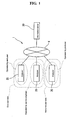
- Fig. 1 is a block diagram showing a structure of an entire body of the information providing system directed to a many item-hemocyte analyzer that performs analysis of blood.
- an information providing system 1 includes a plurality of analyzers 20 and an information server 30 as a database device in which information to be supplied to these analyzers 20 is stored, and they are mutually communicatively connected through a network 4 such as an Internet and a dedicated network.
- the plurality of analyzers 20 are given as examples such as being purchased, possessed, and installed in a facility (end user side) of a hospital and an clinical laboratory, etc, (operated by a service engineer for repairing and adjusting the analyzers 20 possessed by the end user such as stuff of the hospital and the clinical laboratory and the end user), and such as being installed in the facility of a plant, etc, (non-end user side) on the manufacturer side of these analyzers 20 (for example, the manufacturer in the plant operates the analyzer during inspection in a manufacturing intermediate step and assembly work, in a production plant of these analyzers 20).
- the analyzer 20 has an analyzer main body for performing a measurement of a sample such as blood, and a controller 22 for controlling this analyzer main body and collecting/analyzing measurement data.
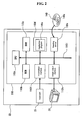
- Fig. 2 is a block diagram showing a hardware structure of the controller 22.
- the controller 22 has a computer mainly constituted of a main body 110, a display unit 26, and an input part 25.
- the main body 110 is mainly constituted of a CPU 110a, a ROM 110b, a RAM 110c, a hard disk 110d, a reading device 110e, an input/output interface 110f, and an image output interface 110h, wherein the CPU 110a, the ROM 110b, the RAM 110c, the hard disk 110d, the reading device 110e, the input/output interface 110f, and the image output interface 110h are connected one another by a bus 110i to attain data communication among them.
- the CPU 110a is capable of executing a computer program stored in the ROM 110b and a computer program loaded into the RAM 110c. Then, when this CPU 110a executes an application program, etc, for realizing an operating system or a system of the present invention, each function block, as will be described later, is realized, and the computer functions as the controller 22.
- the ROM 110b is constituted of a mask ROM, a PROM, an EPROM, and an EEPROM, etc, and the computer program and data used for this computer program executed by the CPU 110a are recorded therein
- the RAM 110c is constituted of a SRAM or a DRAM, etc.
- the RAM 110c is used for reading the computer program recorded in the ROM 110b and the hard disk 110d. In addition, when these computer programs are executed, the RAM 110c is utilized as a working area.
- the hard disk 110d has installed therein various computer programs and the data used for executing these computer programs executed by the CPU 110a, such as the operating system and the application program. Each database as will be described later is also stored in this hard disk 110d.
- the reading device 110Se is constituted of a flexible disk drive, a CD-ROM drive, or a DVD-ROM drive, etc, and can read the computer program or the data recorded in a portable-type recording medium 140.
- the portable-type recording medium 140 stores therein an application program 140a for making the computer function as a system, thus making it possible to make this computer read the application program 140a of the present invention from this portable-type recording medium 140 and install this application program 140a on the hard disk 110d.
- the aforementioned application program 140a is not only provided by the portable-type recording medium 140, but also can be provided through an electrical communication line from an external apparatus communicatively connected to the computer by the electrical communication line (regardless of wired or wireless).
- the aforementioned application program is stored in the hard disk of a server computer for providing the application program on the Internet, it is possible to access this server computer, download this computer program, and install it on the hard disk 110d.
- the input/output interface 110f is constituted of a serial interface such as USB, IEEE1394, RS-232C, a parallel interface such as SCSI, IDE, IEEE1284, and an analogue interface such as a D/A converter and an A/D converter.
- the input part 25 composed of a keyboard and a mouse, etc, is connected to the input/output interface 110f, and by using this input part 25 by a user, the data can be inputted in the computer.
- the image output interface 110h is connected to the display unit 26, being a display constituted of an LCD or a CRT, etc, and outputs to the display unit 26 an image signal in accordance with image data supplied from the CPU 110a.
- the display unit 26 displays an image (screen), in accordance with the image signal thus inputted.
- Fig. 3 is a block diagram showing the function realized by the analyzer 20.
- the controller 22 having the analyzer main body 21 connected thereto for performing a measurement of a sample such as blood has a control part 23 for generally controlling the analyzer main body 21 and controlling each part of this controller 22; a memory 24 composed of the aforementioned hard disk 110d and the RAM 110c, etc; and a communication part 27 for performing communication with outside.
- the input part 25 and the display unit 26 composed of the keyboard and the mouse, etc, as described above are connected to the control part 23.
- the communication part 27 is connected to the information server 30 through a network 4 (Fig. 1), to realize the communication between the controller 22 and the information server 30.
- the display unit 26 displays various kinds of information such as an analysis result, for the operator who operates this analyzer 20.
- the operator can display on the screen of the display unit 26, being the display, an operation part operable by the operator using the input part 25 such as a mouse, etc.
- the "operator" who operates the analyzer 20 includes the aforementioned end user such as stuff of the hospital and the clinical laboratory, the service engineer who visits to the end user side and performs repair/adjustment work, and the manufacturer who performs inspection and adj ustment work in a production plant.
- the control part 23 functionally includes an identification information reception part 23a for receiving identification information such as logon name of the operator who operates the analyzer 20; a group identification part 23b for identifying what group, as will be described later, the aforementioned operator belongs to; an apparatus abnormality specification part 23c for detecting and specifying apparatus abnormalities of the analyzer main body 21; a simple information display unit 23d for displaying the simple information indicating a simple coping process corresponding to the abnormalities of the analyzer main body 21; a coping information display unit 23e for obtaining the coping information indicating a detailed coping process corresponding to a specified apparatus abnormality from the information server 30, and displaying it to the operator, in accordance with the request of the operator; and a position information generation part 23f for generating the position information in the information server 30 in which the coping information required for obtaining the coping information from the information server 30 by the coping information display unit 23e.
- identification information reception part 23a for receiving identification information such as logon name of the operator who operates the analyzer 20
- the identification information reception part 23a displays, on the screen of the display unit 26, a dialog box as will be described later for inputting the logon name as the identification information of the operator, and receives the logon name previously allotted to the operator.
- the group identification part 23b refers to a group identification information database 24b, as will be described later, stored in the memory 24, and identifies what group, as will be described later, the logon name received by the identification information reception part 23a belongs to.
- the apparatus abnormality specification part 23c obtains various kinds of signal information from each kind of sensor, etc, of the analyzer main body 21, and specifies the apparatus abnormality from this signal information.
- the coping information display unit 23e has a function as a web browser for displaying information on the screen of the display unit 26, and displays the coping information obtained from the information server 30 in a window of this web browser.
- the memory 24 stores a simple information database 24a including the simple information corresponding to each of the various kinds of apparatus abnormalities generated in the analyzer main body 21; a group identification information database 24b referenced for identifying the group of the operator by the group identification part 23b; and a position information database 24c referenced for generating the position information by the position information generation part 23f, in addition to the aforementioned operating system and computer program such as an application program.
- the simple information database 24a is so organized that various kinds of apparatus abnormalities generated in the analyzer main body 21 and the simple information as the coping information corresponding to such apparatus abnormalities are correspondingly stored, and the simple information corresponding to the apparatus abnormality generated in the analyzer main body 21 can be easily obtained.
- the group identification information database 24b includes the information used for identifying what group the operator who operates this analyzer 20 belongs to out of a plurality of groups previously divided based on a predetermined attribute.
- three groups are defined, such as "user group”, “service engineer group”, and "manufacturer group”.
- the "user group” is the group constituted by the end user who purchases and possesses this analyzer 20 and performs analysis measurement
- the "service engineer group” is the group constituted by the service engineer who dedicatedly performs inspection, maintenance, and repair of the analyzer 20
- the "manufacturer group” is the group constituted by the manufacturer such as a person in charge of inspection and a person in charge of manufacture who operate the analyzer 20 in the inspection and assembly work in the manufacturing intermediate step of the analyzer 20.
- Fig. 4(b) shows an example of the group identification information database 24b.
- the group identification information database 24b includes the information whereby the logon name allotted to each of a plurality of operators is corresponded to each group, and based on the logon name at the time of log on by the operator, it is possible to identify what group this operator belongs to.
- the information of a password requested to be inputted when the operator inputs the logon name is stored in this group identification database 24b.
- the position information database 24c is so organized, for example, that various kinds of apparatus abnormalities generated in the aforementioned each group and the analyzer main body 21, and addresses in the information server 30 as will be described later allotted to the coping information corresponding to the apparatus abnormalities are correspondingly stored, and the address allotted to the coping information corresponding to the apparatus abnormalities generated in the analyzer main body 21 can be easily generated.
- the controller 22 can be constituted of a personal computer, etc, and this personal computer can be connected to the analyzer main body 21, or the analyzer main body 21 and the controller 22 may be integrally constituted.
- the information server 30 connected to the analyzer 20 through the network 4 has approximately the same hardware structure as that of the controller 22 as shown in Fig. 2, such as a personal computer and a work station, and has a function as a database server and also has a function as a web server.
- Fig. 5 is a block diagram showing the structure of the information server 30.
- the information server 30 has a control part 31 for generally controlling each part of the information server 30; a memory 32 composed of a hard disk and a memory, etc; an input part 33 such as keyboard and mouse; a display unit 34 such as a display, etc, and a communication part 35 for performing communication with the analyzer 20.
- control part 31 selects required information from the coping information databases 32a to 32c corresponding to each group stored in the memory 32, and transmits it to the analyzer 20 through the communication part 35 as the data described in a web data format such as an HTML format.
- the memory 32 stores a coping information database 32a directed to a user group; a coping information database 32b directed to a service engineer group; and a coping information database 32c directed to a manufacturer group, wherein the coping information corresponding to various apparatus abnormalities is made into a database.
- These databases 32a to 32c store group-categorized coping information edited into a content corresponding to the attribute of the aforementioned three groups, by making this coping information into a database for each group.
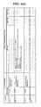
- Figs. 6 (a) to (c) show an example of the aforementioned each coping information databases 32a to 32c stored in the memory 32
- Fig. 6(a) shows the coping information database 32a directed to the user group
- Fig. 6(b) shows the coping information database 32b directed to the service engineer group
- Fig. 6(c) shows the coping information database 32c directed to the manufacturer group, respectively.
- the coping information as the detailed coping information corresponding to the apparatus abnormalities of the analyzer main body 21 is organized and stored.
- this coping information has text data indicating the coping information, image data for illustrating the coping information to the operator or its link, and HTML data for showing them on the web browser, and when this coping information is transmitted to the analyzer 20, a coping information display unit 23 can display such text data and image data, etc, on the web browser.
- the address as the position information used for showing its storage position is individually allotted to the coping information corresponding to these apparatus abnormalities, and when the analyzer 20 requests the coping information, required information is easily specified based on the address generated by the position information generation part 23f.
- the content of the coping information stored in the coping information databases 32a to 32c is edited in accordance with the attribute of the group such as an object and work content of the group and knowledge of a member of the group, and the content different for each group is stored.
- the memory 32 may store a similar database in a different analyzer or the analyzer having a different specification even in a case of the same model.
- the coping information according to the individual case can be stored even in a different analyzer and the analyzer having different specification although having the same model, and the information can be provided.
- the information server 30 is not required to be constituted of one set of personal computer, but may be constituted of a plurality of sets of computer apparatuses.
- the information server 30 receives the access from the analyzer 20 as a web server through the network 4, and provides the coping information stored in the coping information databases 32a to 32c, to the analyzer 20, being an access source, as the HTML data.
- the data is not limited to the HTML data, and other data such as JAVA (registered trademark) and JavaScript (registered trademark) or the data obtained by combining them may be generated and provided to the analyzer 20.
- FIG. 7 is a flowchart showing the operation of the information providing system 1 from the time point when the operator who operates the analyzer 20 starts this analyzer 20 to the time point when the measurement of the sample is possible.
- Fig. 8 is a view showing an example of the dialog box for requesting the operator to log on, displayed on the display unit 34.
- the dialog box 50 in the figure has a logon name input part 51 for inputting the logon name previously allotted to each operator, and a password input part 52 for inputting the password corresponding to the logon name input part 51.
- the operator inputs the logon name and the password allotted to himself/herself by the keyboard, etc, constituting the input part 33, and clicks a button 53 in the dialog box 50.
- the button 53 is clicked, the identification information reception part 23a receives the logon name and the password inputted in the dialog box 50 (step S2) .
- the group identification part 23b determines what group of the aforementioned three groups, the logon name received by the identification information reception part 23a belongs to (step S3).
- the group identification part 23b refers to the group identification information database 24b (Fig. 3), and rejects log on when the inputted logon name belongs to none of the groups, or when the password does not match (step S4) . Therefore, it is possible to exclude a person who does not know the logon name registered in the group identification information database 24b, from logging on. This contributes to preventing an external person from using this analyzer 20 and the information providing system 1.
- the group identification part 23b identifies what group the logon name belongs to, out of the aforementioned three groups, and stores in the memory 24 a group name consequently identified and the inputted logon name (step S5) .
- the analyzer 20 can grasp whether or not the present operator belongs to any one of the groups.
- the operator can give an instruction to perform an analysis operation of the analyzer 20.
- Fig. 9 is a flowchart showing the operation of the information providing system, when the apparatus abnormalities are generated during analysis operation of the analyzer 20.
- the control part 23 determines whether or not the instruction to start analysis operation is received from the operator (step S11), and when so instructed, executes the analysis operation (step S12).
- the apparatus abnormality specification part 23c detects the apparatus abnormalities (step S13).
- the analysis operation is maintained.
- the apparatus abnormality specification part 23c detects the apparatus abnormalities generated in the analyzer main body 21, the apparatus abnormality specification part 23c shuts down the analyzer main body 21 (step S14), and specifies what kind of apparatus abnormalities are generated in the analyzer main body 21 (step S15).
- the apparatus abnormality specification part 23c obtains various kinds of signal information from each kind of sensor, etc, of the analyzer main body 21, and specifies the apparatus abnormalities from this signal information.
- the apparatus abnormality specification part 23c receives a pressure value measured by a pressure sensor incorporated into the analyzer main body 21 as the signal information, and when this pressure value becomes lower than a predetermined threshold value, the apparatus abnormality specification part 23c determines it to be the apparatus abnormality.
- the apparatus abnormality specification part 23c specifies a part becoming a cause of lowering the pressure measured by this pressure sensor, and specifies the apparatus abnormalities. As described above, the apparatus abnormality specification part 23c specifies the apparatus abnormalities that generate in the analyzer main body 21.
- the simple information display unit 23d reads the simple information regarding the apparatus abnormalities thus specified from the simple information database 24a (step S16), and displays a help dialog box showing the read simple information on the screen of the display unit 26 (step S17).
- Fig.10 is a view showing an example of the help dialog box shown in step S17.
- the help dialog box 54 as a coping information display screen has an error display unit 55 for showing the apparatus abnormalities specified by the apparatus abnormality specification part 23c and a simple information display unit 56 for showing the simple information corresponding to the apparatus abnormalities displayed on this error display unit 55.
- the simple information display unit 23d refers to the simple information database 24a stored in the memory 24, and obtains the simple information indicating a simple coping process corresponding to the specified apparatus abnormalities. Then, the obtained simple information is displayed on the simple information display unit 56.
- this help dialog box 54 can be displayed by operating the help dialog box display unit not shown, displayed on the screen of the display unit 26, and for example, can be arbitrarily displayed when the operator is the service engineer and the manufacturer.
- the help dialog box 54 has a detailed information request button 57 for requesting more detailed coping information corresponding to the specified apparatus abnormalities.
- the detailed information request button 57 displayed in the help dialog box 54 can be operated by the operator using the input part 25 such as a mouse, etc.
- the control part 23 selects the detailed information request button 57, namely, determines whether or not the request of the more detailed coping information is received (step S18).
- step S12 the controller 23 starts the analysis operation again (step S12), and in step S13, detects presence/absence of the apparatus abnormalities, and when the aforementioned specified apparatus abnormalities are solved, continues the analysis operation (step S12).
- step S14 the controller 23 shuts down the analyzer main body (step S14), specifies the apparatus abnormalities (step S15), and displays the help dialog box 54 again (steps S16 and S17).
- step S18 when the operator operates the detailed information request button 57 (when the operator requests more detailed coping information), the coping information display unit 23e requests the information server 30 to provide the detailed coping information (step S19).
- the coping information databases 32a to 32c stored in the information server 30, as shown in Figs. 6(a) to (c) a predetermined address is allotted to each coping information corresponding to the apparatus abnormalities.
- the position information generation part 23f generates the address allotted to the coping information corresponding to the specified apparatus abnormalities and a group name (group name identified by the logon name), to which the operator belongs, stored in the memory 24 in step S6 (Fig. 7).
- the coping information display unit 23e requests the information server 30 to transmit the coping information corresponding to the address generated as described above, based on the address generated by the position information generation part 23f.
- the controller 31 of the information server 30 obtains the coping information allotted to the aforementioned address from each of the coping information databases 32a to 32c stored in the memory 32, transmits it to the analyzer 20 as the Web data, and the analyzer 20 receives this Web data (step S18).
- the analyzer 20 identifies and grasps the group to which the operator belongs, and therefore, for example, even if a plurality of analyzers 20 access the information server 30, the information server 30 is not required to perform identification of the operator of each of the analyzers thus accessed, thereby reducing its load.
- the analyzer 20 specifies the address in the information server 30 in which required information is stored, and accesses the information server 30. Therefore, the information serve 30 is not required to perform a complicated processing to the request particularly from the analyzer 20, thereby further reducing its load.
- the analyzer 20 identifies the group to which the operator belongs. However, it can be so constituted that the analyzer 20 transmits the information used for identifying the group such as a logon name, etc, to the information server 30, and the group, to which the operator belongs, can be identified on the side of the information server 30.
- the coping information display unit 23e of the analyzer 20 that receives and obtains the coping information from the information server 30 starts the web browser and displays the window of the web browser on the screen of the display unit 26. Then, it displays the coping information obtained from the information server 30, in the window of the web browser (step S21).
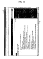
- Fig. 11 and Fig. 12 are views each showing an example of the window of the web browser displayed on the display unit 26.
- the detailed coping information display window 60 has an information display unit 61 for displaying the coping information from the information server 30; an error display unit 62 for showing the apparatus abnormalities which is the subject of the coping information as shown in the information display unit 61; and an error code display unit 63 for showing error codes allotted to the apparatus abnormalities.
- This information display unit 61 displays a view (Fig. 11) for explaining an adjustment part, etc, of the analyzer main body 21 related to the apparatus abnormalities as the image data included in the coping information obtained from the coping information databases 32a to 32c stored in the memory 32 of the information server 30, and a text of the detailed coping process which must be specifically performed to the apparatus abnormalities.
- the information display unit 61 shows the coping information corresponding to the group to which the operator belongs, the operator can cope with the apparatus abnormalities correspondingly to each attribute.
- the coping information corresponding to the group identified by the group identification part 23b, to which the operator belongs can be displayed to the operator, the coping information matching the operator can be provided.
- a search keyword input part 64 for searching in the coping information displayed on the information display unit 61 is provided in the window 60, and required information can be easily extracted from the coping information obtained from the information server 30.
- Fig. 13 shows an example of the window of the browser when a keyword is inputted in the search keyword input part 64 and a search result is shown.
- a window 65 in Fig. 13 shows a result of searching "pressure abnormality" as a keyword, and shows the information including this "pressure abnormality" on a search result display unit 66.
- Each search information 66a shown on this search result display unit 66 is linked with a position wherein each search information 66a is described, in an entire body of the coping information obtained from the information server 30, and by clicking each search information 66a, the coping information of the link is shown, thus making it easy to refer to the coping information.
- the coping information from the information server 30 is displayed to the operator by the web browser on the display unit 26 as a display screen. Therefore, the coping information can be easily browsed and displayed. In addition, the link with other information can be easily set. This contributes to easy usability in obtaining more information.
- Fig. 9 again, by browsing the content of the window 60 (Fig. 11 and Fig. 12), the operator can grasp the coping process performed to the apparatus abnormalities. Then, the operator copes with the apparatus abnormalities by adjusting/repairing the analyzer main body 21 based on this coping process.
- the processing is returned to step S11, and the instruction can be given to perform the analysis operation again.
- the controller 23 starts the analysis operation again (step S12), and in step S13, detects the presence/absence of the apparatus abnormalities, and when the aforementioned specified apparatus abnormalities are solved, continues the analysis operation (step S12).
- the control part 23 shuts down the analyzer main body (step S14), specifies the apparatus abnormalities (step S15), and displays the help dialog box 54 again (steps S16 and S17).
- step S22 determines whether or not the instruction of shutdown by the operator is received. Then, when the instruction of shutdown is not received, the processing is returned to step S11, and receives the instruction to start the analysis operation again.
- a shutdown operation is executed (step S23), and the processing is finished.
- the coping information is the information for coping with the abnormalities of the analyzer.
- the present invention is not limited to the apparatus abnormalities as far as the state needs to be coped with, and the information for coping with the adjustment/inspection at the time of producing the analyzer is also included.
- manufacture/adjustment, assembly/adjustment, or inspection of the apparatus is required, such a state is detected, and the coping information indicating a specific work procedure, etc, is provided to the analyzer from the information server.
- the information providing system of this embodiment it is communicatively connected to the analyzer 20, and is provided with the information server 30 in which the coping information is stored. Therefore, the coping information of enormous information amount is not required to be stored in the analyzer 20. In addition, even when the coping information is provided to a plurality of operators or a plurality of analyzers 20, the coping information can be centrally managed, thereby improving convenience. In addition, by always setting the coping information of the information server 30 in a newest state, newest coping information can be provided to the operator. Further, since the coping information corresponding to the abnormality that generates in the analyzer 20 is displayed, the operator is not required to search and obtain the required information from the manual, etc, thus improving the convenience.
- the convenience is improved for both of the side providing the coping information and the side referencing the coping information, and the newest coping information can be efficiently provided to the operator.
- the coping information provided to the analyzer 20 is centrally managed by the information server 30, and therefore an increase of a management cost can be suppressed.
- the information providing system of the above-described embodiment displays to the operator the simple information indicating a simple coping process, before detailed coping information is displayed. Therefore, the operator is urged to cope with the apparatus abnormalities based on the simple information first. Then, if the repair/adjustment can be made by the response based on the simple information, the analyzer 20 can be restored more quickly.
- the analyzer 20 thus constituted also, the newest and useful coping information can be efficiently provided to the operator, as described above.
- the information providing system of the present invention is not limited to the above-described embodiment.
- the case of using the hemocyte analyzer is exemplified.
- the information providing system of the present invention can be similarly applied to other analyzer.
- the group, to which the operator belongs is divided into three groups such as "a user”, “a service engineer", and "a manufacturer”.
- the group can be further subdivided and can be divided into larger numbers of groups.
- the data of a web format is provided to the analyzer from the information server, and the coping information is displayed by the web browser.
- the present invention is not limited thereto, and it may be so constituted that a dedicated server program for providing the coping information is installed on the information server and also a dedicated browser program for displaying the coping information is installed on the analyzer, thus providing the information to the analyzer from the information server by a dedicated data format.
Landscapes
- Health & Medical Sciences (AREA)
- Engineering & Computer Science (AREA)
- General Health & Medical Sciences (AREA)
- Biomedical Technology (AREA)
- General Business, Economics & Management (AREA)
- Business, Economics & Management (AREA)
- Physics & Mathematics (AREA)
- Analytical Chemistry (AREA)
- Primary Health Care (AREA)
- Public Health (AREA)
- Epidemiology (AREA)
- Life Sciences & Earth Sciences (AREA)
- Chemical & Material Sciences (AREA)
- Medical Informatics (AREA)
- Biochemistry (AREA)
- General Physics & Mathematics (AREA)
- Immunology (AREA)
- Pathology (AREA)
- Automatic Analysis And Handling Materials Therefor (AREA)
- Management, Administration, Business Operations System, And Electronic Commerce (AREA)
Applications Claiming Priority (1)
| Application Number | Priority Date | Filing Date | Title |
|---|---|---|---|
| JP2006094571A JP4965146B2 (ja) | 2006-03-30 | 2006-03-30 | 情報提供システム及び分析装置 |
Publications (2)
| Publication Number | Publication Date |
|---|---|
| EP1840576A2 true EP1840576A2 (fr) | 2007-10-03 |
| EP1840576A3 EP1840576A3 (fr) | 2009-10-07 |
Family
ID=38179539
Family Applications (1)
| Application Number | Title | Priority Date | Filing Date |
|---|---|---|---|
| EP07006536A Withdrawn EP1840576A3 (fr) | 2006-03-30 | 2007-03-29 | Analyseur automatique et système pour fournir des informations |
Country Status (3)
| Country | Link |
|---|---|
| US (2) | US7739079B2 (fr) |
| EP (1) | EP1840576A3 (fr) |
| JP (1) | JP4965146B2 (fr) |
Cited By (9)
| Publication number | Priority date | Publication date | Assignee | Title |
|---|---|---|---|---|
| CN101819199A (zh) * | 2010-05-08 | 2010-09-01 | 桂林市朗道诊断用品有限公司 | 血细胞分析仪用试剂 |
| EP2299277A1 (fr) | 2009-09-17 | 2011-03-23 | F. Hoffmann-La Roche AG | Système d'analyse pour analyser des échantillons biologiques, procédés et produit de programme informatique |
| CN103168303A (zh) * | 2010-08-05 | 2013-06-19 | 霍夫曼-拉罗奇有限公司 | 用于聚合任务数据对象并且用于提供聚合视图的方法 |
| EP2857841A1 (fr) * | 2013-10-07 | 2015-04-08 | Eppendorf Ag | Commande de configuration pour un appareil de laboratoire, appareil de laboratoire doté d'une commande de configuration pour le traitement commandé par un appareil d'au moins un échantillon de laboratoire et procédé de configuration d'un appareil de laboratoire au moyen de la commande de configuration |
| EP2520937A3 (fr) * | 2011-05-02 | 2018-01-24 | Sysmex Corporation | Appareil de traitement d'échantillons |
| US10466262B2 (en) | 2013-10-07 | 2019-11-05 | Eppendorf Ag | Laboratory instrument with access control device and method for instrument-controlled treatment of laboratory samples |
| US10551397B2 (en) | 2013-10-07 | 2020-02-04 | Eppendorf Ag | System comprising at least two laboratory instruments for instrument-controlled handling of a partial problem in a treatment process containing treatments of at least one laboratory sample, laboratory instrument and method |
| EP3517970A4 (fr) * | 2016-09-21 | 2020-06-24 | Hitachi High-Tech Corporation | Appareil d'analyse automatique, système de maintenance à distance et procédé de maintenance |
| US10739362B2 (en) | 2013-10-07 | 2020-08-11 | Eppendorf Ag | Laboratory instrument, system and method for instrument-controlled treatment of at least one laboratory sample using at least one consumable |
Families Citing this family (19)
| Publication number | Priority date | Publication date | Assignee | Title |
|---|---|---|---|---|
| CN101051043B (zh) * | 2006-12-28 | 2011-11-16 | 深圳迈瑞生物医疗电子股份有限公司 | 生化分析仪用户个性化操作的实现方法和装置 |
| JP5280741B2 (ja) * | 2008-06-13 | 2013-09-04 | シスメックス株式会社 | 分析装置の製造支援システム |
| JP5260156B2 (ja) * | 2008-06-17 | 2013-08-14 | 株式会社日立ハイテクノロジーズ | 自動分析装置管理システム |
| US20120116895A1 (en) * | 2010-11-04 | 2012-05-10 | Bank Of America Corporation | Customizable Marketing Campaign Framework |
| JP5641843B2 (ja) * | 2010-09-24 | 2014-12-17 | シスメックス株式会社 | 検体分析システム、検体分析装置および検体分析装置の制御方法 |
| JP5898410B2 (ja) * | 2011-03-30 | 2016-04-06 | シスメックス株式会社 | 検体分析装置 |
| US9036173B2 (en) * | 2011-04-27 | 2015-05-19 | Xerox Corporation | Methods and systems to troubleshoot malfunctions in multifunction devices using a wireless handheld device |
| US9297819B2 (en) * | 2011-07-22 | 2016-03-29 | Sysmex Corporation | Hematology analyzing system and analyzer |
| JP5872816B2 (ja) * | 2011-08-03 | 2016-03-01 | シスメックス株式会社 | 検体分析装置 |
| WO2013065528A1 (fr) | 2011-10-31 | 2013-05-10 | 株式会社日立ハイテクノロジーズ | Système d'analyse automatisé |
| JP5909480B2 (ja) * | 2013-12-25 | 2016-04-26 | シスメックス株式会社 | 検体検査装置及び検査情報出力方法 |
| JP5836516B2 (ja) * | 2015-02-16 | 2015-12-24 | シスメックス株式会社 | 検体処理装置および表示方法 |
| JP5883193B2 (ja) * | 2015-11-27 | 2016-03-09 | シスメックス株式会社 | 検体測定装置および表示方法 |
| JP5894334B1 (ja) * | 2015-11-27 | 2016-03-30 | シスメックス株式会社 | 検体測定装置および表示方法 |
| CN108603893B (zh) * | 2016-02-25 | 2021-10-15 | 株式会社日立高新技术 | 自动分析装置 |
| JP7407671B2 (ja) * | 2020-08-05 | 2024-01-04 | 日本電子株式会社 | 自動分析装置及びプログラム |
| US20240069047A1 (en) * | 2020-12-29 | 2024-02-29 | Beckman Coulter, Inc. | Automated sample analyzer |
| US20240427720A1 (en) | 2023-06-21 | 2024-12-26 | Sysmex Corporation | Maintenance method |
| KR20250007794A (ko) * | 2023-07-06 | 2025-01-14 | 쿠팡 주식회사 | 전자 장치 및 그의 정보 제공 방법 |
Citations (5)
| Publication number | Priority date | Publication date | Assignee | Title |
|---|---|---|---|---|
| EP0672906A1 (fr) | 1994-03-18 | 1995-09-20 | Hitachi, Ltd. | Automate d'analyses |
| JPH10308737A (ja) | 1997-05-06 | 1998-11-17 | Shimadzu Corp | 自動分析装置 |
| EP0973115A2 (fr) | 1998-07-14 | 2000-01-19 | Bayer Corporation | Interface utilisateur pour un système d'analyse biomédicale |
| US20020128728A1 (en) * | 2001-03-09 | 2002-09-12 | Takashi Murakami | Remote maintenance system |
| US20050177345A1 (en) | 1999-11-30 | 2005-08-11 | Sysmex Corporation | Control device and analyzer |
Family Cites Families (15)
| Publication number | Priority date | Publication date | Assignee | Title |
|---|---|---|---|---|
| US5729452A (en) * | 1995-03-31 | 1998-03-17 | Envirotest Acquisition Co. | Method and system for diagnosing and reporting failure of a vehicle emission test |
| JPH09130509A (ja) * | 1995-10-30 | 1997-05-16 | Mita Ind Co Ltd | 複写機管理システム |
| JPH10149064A (ja) * | 1996-11-19 | 1998-06-02 | Canon Inc | 画像処理装置 |
| US6338141B1 (en) * | 1998-09-30 | 2002-01-08 | Cybersoft, Inc. | Method and apparatus for computer virus detection, analysis, and removal in real time |
| US6782345B1 (en) * | 2000-10-03 | 2004-08-24 | Xerox Corporation | Systems and methods for diagnosing electronic systems |
| JP2002230200A (ja) * | 2001-02-06 | 2002-08-16 | Shimadzu Corp | 分析機器保守システム |
| JP2002297796A (ja) * | 2001-03-29 | 2002-10-11 | Hitachi Ltd | ワークフローシステムを用いた問合せ型障害対策支援方法 |
| JP2004013736A (ja) * | 2002-06-10 | 2004-01-15 | Ricoh Co Ltd | 操作表示装置 |
| JP2004072573A (ja) * | 2002-08-08 | 2004-03-04 | Murata Mach Ltd | 機器診断装置及び機器診断システム、通信端末装置 |
| US7185288B2 (en) * | 2003-07-18 | 2007-02-27 | Dade Behring Inc. | Operator interface module segmented by function in an automatic clinical analyzer |
| JP4369247B2 (ja) * | 2004-01-05 | 2009-11-18 | 株式会社日立ハイテクノロジーズ | 自動分析装置のサポートシステム |
| JP2005283344A (ja) * | 2004-03-30 | 2005-10-13 | Shimadzu Corp | Icタグを用いた分析システム及びオートサンプラ |
| US7386761B2 (en) * | 2004-04-16 | 2008-06-10 | International Business Machines Corporation | Diagnostic repair system and method for computing systems |
| US20060156141A1 (en) * | 2004-12-07 | 2006-07-13 | Ouchi Norman K | Defect symptom repair system and methods |
| US20060174167A1 (en) * | 2005-01-28 | 2006-08-03 | Hitachi, Ltd. | Self-creating maintenance database |
-
2006
- 2006-03-30 JP JP2006094571A patent/JP4965146B2/ja not_active Expired - Lifetime
-
2007
- 2007-03-29 EP EP07006536A patent/EP1840576A3/fr not_active Withdrawn
- 2007-03-30 US US11/731,030 patent/US7739079B2/en active Active
-
2010
- 2010-04-30 US US12/771,804 patent/US8010323B2/en not_active Expired - Fee Related
Patent Citations (5)
| Publication number | Priority date | Publication date | Assignee | Title |
|---|---|---|---|---|
| EP0672906A1 (fr) | 1994-03-18 | 1995-09-20 | Hitachi, Ltd. | Automate d'analyses |
| JPH10308737A (ja) | 1997-05-06 | 1998-11-17 | Shimadzu Corp | 自動分析装置 |
| EP0973115A2 (fr) | 1998-07-14 | 2000-01-19 | Bayer Corporation | Interface utilisateur pour un système d'analyse biomédicale |
| US20050177345A1 (en) | 1999-11-30 | 2005-08-11 | Sysmex Corporation | Control device and analyzer |
| US20020128728A1 (en) * | 2001-03-09 | 2002-09-12 | Takashi Murakami | Remote maintenance system |
Cited By (24)
| Publication number | Priority date | Publication date | Assignee | Title |
|---|---|---|---|---|
| CN102024098B (zh) * | 2009-09-17 | 2016-05-18 | 霍夫曼-拉罗奇有限公司 | 用于分析生物样本的分析系统和方法 |
| EP2299277A1 (fr) | 2009-09-17 | 2011-03-23 | F. Hoffmann-La Roche AG | Système d'analyse pour analyser des échantillons biologiques, procédés et produit de programme informatique |
| CN102024098A (zh) * | 2009-09-17 | 2011-04-20 | 霍夫曼-拉罗奇有限公司 | 用于分析生物样本的分析系统、方法和计算机程序产品 |
| US8511549B2 (en) | 2009-09-17 | 2013-08-20 | Roche Diagnostics Operations, Inc. | Analysis system for analyzing biological samples, methods, and computer program product thereof |
| US8651377B2 (en) | 2009-09-17 | 2014-02-18 | Roche Diagnostics Operations, Inc. | Analysis system for analyzing biological samples, methods, and computer program product thereof |
| US8985441B2 (en) | 2009-09-17 | 2015-03-24 | Roche Diagnostics Operations, Inc. | Analysis system for analyzing biological samples, methods, and computer program product thereof |
| CN101819199B (zh) * | 2010-05-08 | 2013-03-20 | 桂林优利特医疗电子有限公司 | 血细胞分析仪用试剂 |
| CN101819199A (zh) * | 2010-05-08 | 2010-09-01 | 桂林市朗道诊断用品有限公司 | 血细胞分析仪用试剂 |
| CN103168303B (zh) * | 2010-08-05 | 2018-07-31 | 霍夫曼-拉罗奇有限公司 | 用于聚合任务数据对象并且用于提供聚合视图的方法 |
| US9927941B2 (en) | 2010-08-05 | 2018-03-27 | Roche Diagnostics Operations, Inc. | Method for aggregating task data objects and for providing an aggregated view |
| CN103168303A (zh) * | 2010-08-05 | 2013-06-19 | 霍夫曼-拉罗奇有限公司 | 用于聚合任务数据对象并且用于提供聚合视图的方法 |
| EP3640649A1 (fr) * | 2011-05-02 | 2020-04-22 | Sysmex Corporation | Méthode implémentée dans un ordinateur dans un appareil de traitement d'échantillons |
| EP2520937A3 (fr) * | 2011-05-02 | 2018-01-24 | Sysmex Corporation | Appareil de traitement d'échantillons |
| USRE49503E1 (en) | 2011-05-02 | 2023-04-25 | Sysmex Corporation | Sample processing apparatus |
| EP3926344A1 (fr) * | 2011-05-02 | 2021-12-22 | Sysmex Corporation | Appareil de traitement d'échantillons |
| USRE48189E1 (en) | 2011-05-02 | 2020-09-01 | Sysmex Corporation | Sample processing apparatus |
| US10551397B2 (en) | 2013-10-07 | 2020-02-04 | Eppendorf Ag | System comprising at least two laboratory instruments for instrument-controlled handling of a partial problem in a treatment process containing treatments of at least one laboratory sample, laboratory instrument and method |
| US10739362B2 (en) | 2013-10-07 | 2020-08-11 | Eppendorf Ag | Laboratory instrument, system and method for instrument-controlled treatment of at least one laboratory sample using at least one consumable |
| EP2857841A1 (fr) * | 2013-10-07 | 2015-04-08 | Eppendorf Ag | Commande de configuration pour un appareil de laboratoire, appareil de laboratoire doté d'une commande de configuration pour le traitement commandé par un appareil d'au moins un échantillon de laboratoire et procédé de configuration d'un appareil de laboratoire au moyen de la commande de configuration |
| US10466262B2 (en) | 2013-10-07 | 2019-11-05 | Eppendorf Ag | Laboratory instrument with access control device and method for instrument-controlled treatment of laboratory samples |
| US11536738B2 (en) | 2013-10-07 | 2022-12-27 | Eppendorf Se | System comprising at least two laboratory instruments for instrument-controlled handling of a partial problem in a treatment process containing treatments of at least one laboratory sample, laboratory instrument and method |
| US10452035B2 (en) | 2013-10-07 | 2019-10-22 | Eppendorf Ag | Laboratory instrument for instrument-controlled treatment of at least one laboratory sample |
| US12385932B2 (en) | 2013-10-07 | 2025-08-12 | Eppendorf Se | Laboratory instrument, system and method for instrument-controlled treatment of at least one laboratory sample using at least one consumable |
| EP3517970A4 (fr) * | 2016-09-21 | 2020-06-24 | Hitachi High-Tech Corporation | Appareil d'analyse automatique, système de maintenance à distance et procédé de maintenance |
Also Published As
| Publication number | Publication date |
|---|---|
| JP4965146B2 (ja) | 2012-07-04 |
| US8010323B2 (en) | 2011-08-30 |
| EP1840576A3 (fr) | 2009-10-07 |
| US20100274498A1 (en) | 2010-10-28 |
| JP2007271334A (ja) | 2007-10-18 |
| US7739079B2 (en) | 2010-06-15 |
| US20070233303A1 (en) | 2007-10-04 |
Similar Documents
| Publication | Publication Date | Title |
|---|---|---|
| US7739079B2 (en) | Information providing system and analyzer | |
| JP6749453B2 (ja) | プロセス制御システムに検索サービスを提供するためのシステム、方法、製品、プログラム | |
| JP6552993B2 (ja) | プロセス制御情報を表示する方法及び装置、機械がアクセス可能な媒体、及びデバイス記述ファイル内にスクリプト拡張機能を作成する方法 | |
| US9494931B2 (en) | Dynamic hyperlinks for process control systems | |
| US6604023B1 (en) | Managing an environment utilizing a portable data processing system | |
| US7865907B2 (en) | Method and apparatus for providing automatic software updates | |
| EP3105642B1 (fr) | Système de mise en service de dispositif de terrain et procédé de mise en service de dispositif de terrain | |
| JP2012074037A (ja) | プロセスデータを管理する方法および装置 | |
| US6636808B1 (en) | Managing an environment via a universally accessible server system | |
| US11531669B2 (en) | Systems and methods to assess and repair data using data quality indicators | |
| CN102985925B (zh) | 用于提供自动更新的产品插页的系统和方法 | |
| JP5293061B2 (ja) | 機器管理プログラム及び機器管理システム | |
| JP2000242328A (ja) | サーベイランス試験装置およびプログラムを記憶した記憶媒体 | |
| JP2004003960A (ja) | 重量測定装置を備えたプログラム可能なシステムおよびそのようなシステムをプログラミングする方法、ならびにこの方法を実行するソフトウエア | |
| US8010223B2 (en) | Quality control system and quality control information delivery device | |
| JP5204270B2 (ja) | 情報提供システム及び分析装置 | |
| CA3188729C (fr) | Systemes et procedes d'evaluation et de reparation de donnees au moyen d'indicateurs de qualite de donnees | |
| JP2021118578A (ja) | コンピュータプログラム、データ記録方法及び情報処理装置 | |
| JP2011227885A (ja) | ソフトウェアの検査種別判定装置 | |
| US11681820B2 (en) | Computer system and data access control method | |
| JP5280741B2 (ja) | 分析装置の製造支援システム | |
| US20070174559A1 (en) | Control system and method | |
| CN118969228A (zh) | 一种用于神经外科医疗器材管理系统 | |
| JP2001319286A (ja) | 分析計ならびに分析計の遠隔監視操作システムおよび遠隔保守方法 | |
| CN115878724A (zh) | 一种poct数据处理系统及其使用方法 |
Legal Events
| Date | Code | Title | Description |
|---|---|---|---|
| PUAI | Public reference made under article 153(3) epc to a published international application that has entered the european phase |
Free format text: ORIGINAL CODE: 0009012 |
|
| AK | Designated contracting states |
Kind code of ref document: A2 Designated state(s): AT BE BG CH CY CZ DE DK EE ES FI FR GB GR HU IE IS IT LI LT LU LV MC MT NL PL PT RO SE SI SK TR |
|
| AX | Request for extension of the european patent |
Extension state: AL BA HR MK YU |
|
| PUAL | Search report despatched |
Free format text: ORIGINAL CODE: 0009013 |
|
| AK | Designated contracting states |
Kind code of ref document: A3 Designated state(s): AT BE BG CH CY CZ DE DK EE ES FI FR GB GR HU IE IS IT LI LT LU LV MC MT NL PL PT RO SE SI SK TR |
|
| AX | Request for extension of the european patent |
Extension state: AL BA HR MK RS |
|
| RIC1 | Information provided on ipc code assigned before grant |
Ipc: G06F 19/00 20060101ALI20090828BHEP Ipc: G01N 35/00 20060101AFI20070703BHEP |
|
| 17P | Request for examination filed |
Effective date: 20100121 |
|
| AKX | Designation fees paid |
Designated state(s): AT BE BG CH CY CZ DE DK EE ES FI FR GB GR HU IE IS IT LI LT LU LV MC MT NL PL PT RO SE SI SK TR |
|
| 17Q | First examination report despatched |
Effective date: 20100708 |
|
| STAA | Information on the status of an ep patent application or granted ep patent |
Free format text: STATUS: THE APPLICATION IS DEEMED TO BE WITHDRAWN |
|
| 18D | Application deemed to be withdrawn |
Effective date: 20170809 |