EP1840686B1 - Positionsbestimmungseinrichtung und positionsbestimmungsverfahren - Google Patents
Positionsbestimmungseinrichtung und positionsbestimmungsverfahren Download PDFInfo
- Publication number
- EP1840686B1 EP1840686B1 EP05703809.3A EP05703809A EP1840686B1 EP 1840686 B1 EP1840686 B1 EP 1840686B1 EP 05703809 A EP05703809 A EP 05703809A EP 1840686 B1 EP1840686 B1 EP 1840686B1
- Authority
- EP
- European Patent Office
- Prior art keywords
- positioning
- length measuring
- coordinate value
- movement
- moving
- Prior art date
- Legal status (The legal status is an assumption and is not a legal conclusion. Google has not performed a legal analysis and makes no representation as to the accuracy of the status listed.)
- Expired - Lifetime
Links
Images






Classifications
-
- G—PHYSICS
- G05—CONTROLLING; REGULATING
- G05B—CONTROL OR REGULATING SYSTEMS IN GENERAL; FUNCTIONAL ELEMENTS OF SUCH SYSTEMS; MONITORING OR TESTING ARRANGEMENTS FOR SUCH SYSTEMS OR ELEMENTS
- G05B19/00—Program-control systems
- G05B19/02—Program-control systems electric
- G05B19/18—Numerical control [NC], i.e. automatically operating machines, in particular machine tools, e.g. in a manufacturing environment, so as to execute positioning, movement or co-ordinated operations by means of program data in numerical form
- G05B19/404—Numerical control [NC], i.e. automatically operating machines, in particular machine tools, e.g. in a manufacturing environment, so as to execute positioning, movement or co-ordinated operations by means of program data in numerical form characterised by control arrangements for compensation, e.g. for backlash, overshoot, tool offset, tool wear, temperature, machine construction errors, load, inertia
-
- B—PERFORMING OPERATIONS; TRANSPORTING
- B23—MACHINE TOOLS; METAL-WORKING NOT OTHERWISE PROVIDED FOR
- B23Q—DETAILS, COMPONENTS, OR ACCESSORIES FOR MACHINE TOOLS, e.g. ARRANGEMENTS FOR COPYING OR CONTROLLING; MACHINE TOOLS IN GENERAL CHARACTERISED BY THE CONSTRUCTION OF PARTICULAR DETAILS OR COMPONENTS; COMBINATIONS OR ASSOCIATIONS OF METAL-WORKING MACHINES, NOT DIRECTED TO A PARTICULAR RESULT
- B23Q17/00—Arrangements for observing, indicating or measuring on machine tools
- B23Q17/24—Arrangements for observing, indicating or measuring on machine tools using optics or electromagnetic waves
- B23Q17/248—Arrangements for observing, indicating or measuring on machine tools using optics or electromagnetic waves using special electromagnetic means or methods
- B23Q17/2485—Arrangements for observing, indicating or measuring on machine tools using optics or electromagnetic waves using special electromagnetic means or methods using interruptions of light beams
-
- G—PHYSICS
- G05—CONTROLLING; REGULATING
- G05B—CONTROL OR REGULATING SYSTEMS IN GENERAL; FUNCTIONAL ELEMENTS OF SUCH SYSTEMS; MONITORING OR TESTING ARRANGEMENTS FOR SUCH SYSTEMS OR ELEMENTS
- G05B19/00—Program-control systems
- G05B19/02—Program-control systems electric
- G05B19/18—Numerical control [NC], i.e. automatically operating machines, in particular machine tools, e.g. in a manufacturing environment, so as to execute positioning, movement or co-ordinated operations by means of program data in numerical form
- G05B19/19—Numerical control [NC], i.e. automatically operating machines, in particular machine tools, e.g. in a manufacturing environment, so as to execute positioning, movement or co-ordinated operations by means of program data in numerical form characterised by positioning or contouring control systems, e.g. to control position from one programmed point to another or to control movement along a programmed continuous path
- G05B19/27—Numerical control [NC], i.e. automatically operating machines, in particular machine tools, e.g. in a manufacturing environment, so as to execute positioning, movement or co-ordinated operations by means of program data in numerical form characterised by positioning or contouring control systems, e.g. to control position from one programmed point to another or to control movement along a programmed continuous path using an absolute digital measuring device
-
- G—PHYSICS
- G05—CONTROLLING; REGULATING
- G05B—CONTROL OR REGULATING SYSTEMS IN GENERAL; FUNCTIONAL ELEMENTS OF SUCH SYSTEMS; MONITORING OR TESTING ARRANGEMENTS FOR SUCH SYSTEMS OR ELEMENTS
- G05B2219/00—Program-control systems
- G05B2219/30—Nc systems
- G05B2219/37—Measurements
- G05B2219/37125—Photosensor, as contactless analog position sensor, signal as function of position
-
- G—PHYSICS
- G05—CONTROLLING; REGULATING
- G05B—CONTROL OR REGULATING SYSTEMS IN GENERAL; FUNCTIONAL ELEMENTS OF SUCH SYSTEMS; MONITORING OR TESTING ARRANGEMENTS FOR SUCH SYSTEMS OR ELEMENTS
- G05B2219/00—Program-control systems
- G05B2219/30—Nc systems
- G05B2219/43—Speed, acceleration, deceleration control ADC
- G05B2219/43115—Adaptive stopping
Definitions
- the present invention relates to a positioning device, and more particularly to instrumentation of a non-contact measurement with high precision.
- the conventional positioning device for electric discharge machining or cutting work achieves the high precision positioning by an electrical contact sensing method between a work piece and an electrode or tool, using the conductivity of the work piece or tool electrode (e.g., refer to patent document 1).
- a positioning method for positioning a table by driving a drive mechanism based on the detection result of the rough feed amount in a first position detection sensor and the detection result of the minute feed amount in a second position detection sensor, in which the first position detection sensor detects the rough feed amount of the table on which the work piece is laid and the second position detection sensor detects the minute feed amount (e.g., refer to patent document 3).
- the conventional positioning device using proximate contact sensing means had a problem that the measuring time was longer because the approach speed must be decreased to suppress a physical damage between the measuring object and the object to be measured and suppress the impact at the time of contact. Also, a contact sensing probe was required to have the increased rigidity to suppress deformation due to a pressure at the time of contact, and accordingly a spherical portion at the probe tip was required to have a fixed size or greater. Therefore, there was a drawback that the measurement of a minute shape portion was impossible because the spherical portion at the probe tip could not be made closer to the minute shape portion. In such a case, since a special measuring instrument having a pin gauge was employed, it was required that the measurement object was once taken out and measured off-line.
- the minute pin shape is so minute that the measured object is deformed due to a contact pressure by probe contact, whereby the measurement itself becomes impossible.
- the measurement section was enlarged and the shape was measured off-line using the microscope with the CCD camera, as described above.
- the long distance measurement laser displacement sensor when a long distance measurement laser displacement sensor is employed, a very minute object can be measured owing to the non-contact measurement.
- the typical long distance measurement laser has a resolution of 10 ⁇ m and an error of about 0.2mm, it is difficult to employ the long distance measurement laser displacement sensor as high precision positioning means.
- the long distance measurement laser displacement sensor is limited to the use in the field of simple shape determination on the assembly line or the like, for example, and is difficult to apply for the positioning control for electric discharge machining, for example, for which the high precision operation (resolution of about 0.1 ⁇ m) is required.
- the error can be suppressed below about 5 ⁇ m, but the length measurable range of the high precision laser length measuring machine is restricted to about 10mm ⁇ 1mm, and the high precision laser measuring machine and the measuring object must be laid in a range of about 10mm ⁇ 1mm, whereby its practical direct use is difficult. Also, in a working machine that is controlled in a unit of drive with a resolution of 0.1 ⁇ m, it is difficult to measure a high precision work that is processed in a unit of submicron, and substitute for the conventional contact positioning.
- This invention has been achieved to solve the above-mentioned problems, and it is an object of the invention to provide a positioning device capable of performing the precise positioning operation at high speed without need of apprehending a collision at the time of measurement and without need of preparing a positioning program based on a plurality of shape data for each measurement shape.
- the positioning device comprises non-contact length measuring means, means for stopping the measurement object approaching at high speed at the stage of entering any length measuring distance, based on positional data from the length measuring means, means for automatically correcting for the overshoot amount with the positional data, and controlling the shaft to any position, and means for reading the NC coordinate value of the main shaft after the automatic correction, whereby there is the effect that it is unnecessary to apprehend a collision at the time of measurement, and the precise positioning operation can be performed at high speed.
- Fig. 1 shows the constitution of a positioning device according to an embodiment 1 of the present invention, which is applied to an electric discharge machine.
- the electric discharge machine comprises shaft control means 1 such as NC, shaft driving means 2, a main shaft head portion 3, a processing vessel 4 and a surface plate 5.
- shaft control means 1 such as NC
- shaft driving means 2 a main shaft head portion 3
- processing vessel 4 a processing vessel 4
- surface plate 5 a surface plate 5.
- a tool electrode 6 is installed on the main shaft head portion and a work piece 7 is placed on the surface plate.
- a non-contact sensor 8 represented by a laser displacement gauge is mounted on a removable sensor unit 9, which is mounted on the main shaft portion through a sensor mounting guide 10.
- an output signal from the non-contact sensor 8 is sent to the shaft control means 1 and an optimal shaft feed command is issued to the shaft driving means 2 by the positioning control means 11.
- Fig. 2 shows an output signal from the non-contact sensor 8
- Fig. 3 shows a system flow in which the drive means 2 performs the optimal measurement operation based on the output signal under the control of the positioning control means 11.
- the high precision non-contact sensor as described in this embodiment has a limited length measurement range, which is generally as large as about 30mm ⁇ 2mm for the resolution of 0.5 ⁇ m and about 5mm ⁇ 0.3mm for the resolution of 0.1 ⁇ m.
- the output signal from the non-contact sensor 8 is switched between H and L at any position in the length measurement range (typically an intermediate position in the length measurement range) in accordance with the output specification.
- means for generating the signal at any position is illustrated, but another method may be alternatively employed.
- the non-contact sensor 8 and a measured portion of the work piece 7 can be moved in a fixed distance and the coordinate value of the drive shaft at that time can be read by the shaft control means 1.
- the shaft driving portion 2 drives the main shaft head portion 3, based on a command from the shaft control means 1, so that the non-contact sensor 8 mounted on the removable sensor unit 9 performs the relative movement(approaching motion)to a measured portion (measurement object 21) of the work piece 7.
- the non-contact sensor 8 has the length measurement range as described above. If the measurement object 21 is detected at any position (e.g., an intermediate position of the length measurement range), the output signal switches from L to H, in which the output signal is maintained at the H level within the length measurement range and becomes the L level out of the length measurement range.
- the positioning operation of this embodiment makes effective use of detection in this length measurement range.
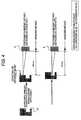
- a positioning process as shown in Fig. 3 will be described below using an operation concept view as shown in Fig. 4 .
- S1 When the positioning command is executed, the fast shaft movement is performed in the direction toward the object of measurement (+ direction in this case) so that the sensor head portion is moved to the measurement object.
- the fast shaft movement can be set at the maximum speed (e.g., 50m/min in the case of linear driving) that is settable in the NC control device 1.
- the positioning control means 11 such as NC reads the coordinate value (coordinateA) of the drive shaft at the position of S7).
- This coordinate value (coordinate A) is the coordinate value moved in one direction by the overshoot amount when the shaft is moved in one direction by the minimum unit of the fixed period at a minute feed speed from the target position (30mm) where the shaft is essentially positioned.
- S9) After reading the coordinate value (coordinate A), the shaft subsequently makes an approach at the minute feed speed in the opposite direction (+ direction) to that of S7).
- the shaft movement is stopped (third position) when the output signal is H by referring to the output signal at every fixed period in approaching in the opposite direction (+ direction).
- the shaft control means such as NC reads the coordinate value (coordinate B) of the shaft movement at the position of S10).
- This coordinate value (coordinate B) is the coordinate value moved in + direction by the overshoot amount when the shaft is moved in + direction by the minimum unit of the fixed period at the minute feed speed from the target position where the shaft is essentially positioned.
- the shaft is moved to the middle point between coordinate A and coordinate B by checking the hysteresis value of the output signal due to a difference in the approach direction (a discrepancy of the detection value when the detection value is different depending on the approach direction (+ direction and - direction) in order to remove the influence of hysteresis.
- the coordinate is read at the final positioning completion location (coordinate C) to which the shaft is moved.
- this measuring method has a feature of performing the measurement in non-contact manner, there is the advantage that the measurement precision is not affected, irrespective of whether the overshoot amount is large or small. Also, there is no damage due to collision unless the overshoot amount exceeds the distance between the measurement object and the target coordinate (approach target), whereby the movement speed can be increased. If the overshoot amount is too large, the coordinate correction time up to the target coordinate is increased, whereby it is required to appropriately set the movement speed for the shaft return to shorten the measuring time as much as possible.
- the overshoot amount is 8.3mm, estimating the delay time as 0.01 seconds, whereby there is no fear that the problem such as collision arises with the device of this embodiment.
- the non-contact sensor 8 is positioned at the position a fixed distance (30mm in this embodiment) away from each of the measurement reference point and the depthmeasurement point, and a difference between both the NC coordinate values is calculated, whereby the precise depth data can be acquired rapidly. It is not required that the operator intervenes in the positioning, whereby the automation can be easily made using the program or the system.
- Fig. 5 is data representing the error amount of a typical laser length measuring instrument.
- the X-axis (transverse axis) of the graph represents the read value of the drive coordinate for the distance between the laser head and the measurement object by the drive control means such as NC.
- the Y-axis (longitudinal axis) represents the difference (error amount) from coordinate data recognized by the laser length measuring machine at that time when the coordinate value is positive.
- the measurement range specification of the laser length measuring machine is from 28mm to 30mm.
- Fig. 5A shows data of 28mm to 30mm from the drive coordinate value
- Fig. 5B shows data of 29.9mm to 30.1mm
- Fig. 5C shows data of 29.99mm to 30.01mm.
- the error amount of the Y-axis should be always zero.
- the error amount increases or decreases according to the measurement distance, indicating a limitation of the H/W precision in the current laser length measurement precision.
- the maximum error amount is 51 ⁇ m in a full measurement range of ⁇ 2mm.
- the repeat accuracy (Data (1) to (3)) is also acquired, and the measurement results of making measurements three times under the same conditions are indicated at the same time. As a result, there is dispersion in three measurement results. That is, it is difficult to make the absolute position measurement at high precision in the full range of ⁇ 2mm.
- the laser length measuring instrument makes the adjustments so that the measurement error may be minimized at an intermediate location in the measurement range, whereby the repeat accuracy at the same location (30mm in this case) is suppressed to 1 ⁇ m or less (see Fig. 5C ).
- the laser length measuring instrument has a very small error in measuring the measurement object any distance away (30mm in this case). Therefore, it is possible to make the positioning of the measurement object at the position any distance away at very high precision, using the laser length measuring instrument, whereby the positioning system of this embodiment employs this scheme.
- the numerical control tool machine with drive means for moving the main shaft and the sensor portion it is a mandatory requirement for improving the measurement precision to assure a certain static precision.
- the positioning device comprises non-contact length measuring means, means for stopping the measurement object approaching at high speed at the stage of entering any length measuring distance, based on the positional data from the length measuring means, means for automatically correcting for the overshoot amount with the positional data and controlling the shaft to any position, and means for reading the NC coordinate value of the main shaft after the automatic correction, whereby there is the effect that the precise positioning operation can be performed at high speed without apprehending the collision at the time of measurement.
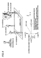
- Fig. 6 shows a positioning device according to an embodiment 2.
- non-contact length measuring means are further provided, including + X-axis sensor 31, - X-axis sensor 32, + Y-axis sensor 33, - Y-axis sensor 34 and Z-axis sensor 35 in a total of five axis directions.
- the relative coordinate values between sensors are obtained beforehand.
- Fig. 7 shows a positioning process for measuring the misalignment correction amount of the measuring object (tool electrode or the like) with respect to the main shaft.
- the electrode is installed beforehand on the Z-axis sensor 35 (separatedby 30mm or more), and if a Z-axis positioning command is executed, the electrode is positioned at high speed in the Z-axis direction toward the Z-axis sensor.
- the process to be performed is the same as shown in the embodiment 1, and the details are omitted.
- the shaft control means 1 represented by the NC reads the coordinate value for the stop coordinate of the drive system. This coordinate value indicates the coordinate correctly 30mm above the Z-axis sensor 35.
- the electrode is installed (30mm or more away) near the + X-axis sensor 31.
- the operator manually operates the drive system simply, or the automatic control may be made in accordance with a program based on the electrode shape data acquired beforehand, and the position coordinate value of the + X-axis sensor 31.
- a + X-axis direction positioning command is executed.
- the electrode is positioned in the + X-axis sensor direction at high speed in the same manner as above, and after the completion, the drive coordinate is read by the NC. This coordinate value indicates the coordinate correctly -30mm from the + X-axis sensor 31.
- the positions of the + X-axis sensor and the - X-axis sensor are already known, and therefore the center coordinate A between the positions of the X-axis sensor and the - X-axis sensor is already known, whereby if the electrodes are symmetrical, the center coordinate B between the coordinate value acquired at S21) and the coordinate value acquired at S22) should be matched with the coordinate A. However, if the coordinate A and the coordinate B are unmatched, the electrodes are not symmetrical, producing the misalignment amount of the electrode.
- the electrode is moved on the axial line of the Y-axis sensor.
- the operator manually operates the drive system simply, or the automatic control may be made in accordance with the program based on the electrode shape data and the position coordinate value of the + Y-axis sensor 33 acquired beforehand in the same manner as when the electrode is installed on the X-axis sensor.
- a positioning command in the + Y-axis direction is executed.
- the electrode is positioned at high speed in the + Y-axis sensor direction and after the completion, the drive coordinate is read by the NC in the same manner as above. This coordinate value indicates the coordinate correctly -30mm from the + Y-axis sensor 33.
- the steps S22 and S23 may be performed again, as needed, whereby the misalignment amount in the X direction is measured again to minimize the error amount.
- the approach speed for positioning can be greatly higher than the conventional contact positioning.
- the fast positioning operation at a speed of 1000mm/min or greater is allowed in this embodiment. Also, the faster operation can be performed by using the linear drive system.
- the non-contact sensors in a total of five axis directions are required to correct for misalignment in the embodiment 2, the correction for misalignment can be made in the same manner by the non-contact sensors with a total of two axes including one axis on the XY plane and one axis in the Z-axis direction by the concurrent use of the C-axis (rotation axis) on the main shaft.
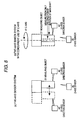
- Fig. 8 shows a positioning system when the C-axis is used concurrently. Instead of making the measurement from four directions on the XY plane, the measurement object can be measured from four directions ( ⁇ X, ⁇ Y) by using only the sensor in one axis direction owing to the rotation around the C-axis.
- the measurement object is rotated in four directions of C0°, C90°, C180° and C270°, and the following process is performed, as shown in Fig. 9 .
- S31) The laser length measuring instrument and the measurement obj ect are controlled in any distance at the position C0°, whereby the coordinate value A at this time is acquired (the positioning process is clearly specified in the embodiment 1).
- S32) The coordinate value B is acquired by making the same control at the position of C180°.
- the misalignment amount x is calculated from the expression 1 (see the following for the calculation expression).
- the coordinate value D is acquired by making the same control at the position of C90°.
- S35) The coordinate value E is acquired by making the same control at the position of C270°.
- S36) The misalignment amount y is calculated from the expression 2 (see the following for the calculation expression).
- m ⁇ 2 Dx - Cx
- n ⁇ 2 Ex - Cx (Cx is the known value.)
- the rotation of the C-axis is used in measuring the misalignment of the electrode, presupposing that there is no misalignment in the C-axis itself.
- the misalignment amount exists for the rotation, it is required to measure in advance the C-axis misalignment amount at 90°, 180° and 270° with respect to 0°.
- the misalignment amounts in the X direction at 90°, 180° and 270° are X90, X180 and X270
- the non-contact lengthmeasuring means in each axis direction can be shared by comprising the C-axis drive portion of the main shaft, whereby it is possible to implement the high precision correction for misalignment of the tool electrode with respect to the main shaft at high speed.
- Fig. 10 shows an application example of a positioning device according to an embodiment 4, which is applied to an electric discharge machine.
- the electric discharge machine comprises shaft control means 1, shaft driving means 2 and the main shaft head portion 3.
- the non-contact sensor 8 represented by a laser displacement gauge capable of making the measurement in the XYZ axis directions as shown in the embodiments 1 and 2 is mounted as shown in Fig. 6 .
- a thermal displacement correction reference block 52 is directly attached on the main shaft 3, whereby a mechanical thermal displacement amount can be measured with the reference block 52 as a representative point.
- the non-contact sensor 8 measures the reference block 52, and if its position measurement result is different as time progresses, its value can be considered as the mechanical thermal displacement amount.
- An output signal from the non-contact sensor 8 is sent to the shaft control means 1, whereby the positioning control means 11 makes an optimal shaft feed command to the shaft driving means 2 to correct for the mechanical thermal displacement amount.
- the fast positioning of the thermal displacement correction reference block 52 made of ceramics material and attached on the main shaft 3 is performed at every fixed periodic interval (e.g., the acquisition interval being arbitrarily settable from one second to one minute) as in the embodiment 1, whereby the positioning control means 11 acquires the NC coordinate value after positioning. Since the displacement of the NC coordinate value occurs in accordance with a change in the temperature under the environment where the machine tool is installed, and indicates the mechanical thermal displacement amount of the structure, which is mainly casting, the mechanical thermal displacement amount is acquired at every fixed period.
- the thermal displacement correctionmeans 51 can control the acquired mechanical thermal displacement amount by adding the correction value to the intrinsic positional command on the S/W control for every NC command of the drive control device so that the driving operation may cancel the mechanical thermal displacement amount.
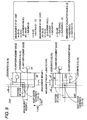
- Fig. 11 shows the relationship of the mechanical thermal displacement amount relative to the mechanical temperature change.
- the mechanical thermal displacement amount can be calculated from the mechanical temperature change as shown in Fig. 11 by configuring an approximate expression, but there is a limitation on the correction for the mechanical thermal displacement amount because of an approximate solution insistently. In the case of the correction with the approximate expression, the correction for the mechanical thermal displacement amount is limited to about 1/2. For example, when the mechanical thermal displacement amount at the tip of the electrode is 20 ⁇ m, an error amount caused by the thermal displacement of about 10 ⁇ m still remains even if the correction is made.
- the error amount can be made zero in principle immediately after the measurement, whereby it is beneficial that the mechanical thermal displacement amount is directly measured as in this embodiment to accurately correct for the mechanical thermal displacement amount to make the high precision working.
- the measurement is directly made as in this embodiment, the working is interrupted and there is a waste time due to the measurement of the thermal displacement correction reference block 52, but if the non-contact measurement method as in the above embodiments is employed, the shaft movement speed canbe increasedup to a mechanical tolerance limit, whereby the waste time can be suppressed.
- the positioning device according to this invention is suitably used as positioning means in various types of numerical control machine tools.
Landscapes
- Engineering & Computer Science (AREA)
- Physics & Mathematics (AREA)
- Human Computer Interaction (AREA)
- Manufacturing & Machinery (AREA)
- General Physics & Mathematics (AREA)
- Automation & Control Theory (AREA)
- Electromagnetism (AREA)
- Optics & Photonics (AREA)
- Mechanical Engineering (AREA)
- Automatic Control Of Machine Tools (AREA)
- Numerical Control (AREA)
- Length Measuring Devices With Unspecified Measuring Means (AREA)
- Control Of Position Or Direction (AREA)
Claims (11)
- Positionierungsvorrichtung, umfassend:- Bewegungsmittel (2) zum relativen Bewegen eines Positionierungsobjekts (21) und Längenmessmittel (8) zum Messen des Abstands von dem Längenmessmittel bis zu dem Positionierungsobjekt (21) auf kontaktlose Art und Weise und zum Ausgeben eines Detektionssignals, wenn das Positionierungsobjekt (21) von dem Längenmessmittel (8) nur in einer Längenmessfläche innerhalb einer vorherbestimmten Reichweite von einer Detektionsposition, die eine Zielposition des Bewegungsmittels (2) ist, erkannt wird;- Wellensteuermittel (1) zum: Anhalten des Bewegungsmittels (2), wenn das Detektionssignal des Längenmessmittels (8) erkannt wird; Bewegen des Bewegungsmittels (2) von einer ersten Position, in der die Bewegung tatsächlich angehalten ist, in die Detektionsposition, Anhalten des Bewegungsmittels (2), wenn erkannt wird, dass sich das Bewegungsmittel (2) außerhalb der Längenmessfläche befindet, und Erfassen eines Koordinatenwertes einer zweiten Position, in der die Bewegung tatsächlich angehalten ist; und Bewegen des Bewegungsmittels (2) von der zweiten Position in die Detektionsposition, und Anhalten des Bewegungsmittels (2), wenn das Bewegungsmittel (2) die Detektionsposition erreicht, und Erfassen eines Koordinatenwertes einer dritten Position, in der die Bewegung angehalten ist und somit das Wellensteuermittel (1) einen Überlauf zwischen der Halteposition und der Detektionsposition automatisch korrigiert, wenn das Bewegungsmittel (2) das Positionierungsobjekt (21) und das Längenmessmittel (8) relativ bewegt; und- Positionierungssteuermittel (11) zum Speichern eines Referenzkoordinatenwertes basierend auf den Koordinatenwerten der zweiten Position und der dritten Position nach der automatischen Korrektur durch das Wellensteuermittel (1) und Ausführen des Positionierens basierend auf dem Referenzkoordinatenwert.
- Positionierungsvorrichtung nach Anspruch 1, dadurch gekennzeichnet, dass die Überlaufkorrektur für das Positionierungssteuermittel erfolgt durch Ausführen einer langsamen Bewegung von der ersten Position, in der die Bewegung tatsächlich von der Detektionsposition in der Längenmessfläche anhält, in die Detektionsposition, Erfassen des Koordinatenwertes der zweiten Position, in der die Bewegung anhält, durch Erkennen, dass sich das Positionierungsobjekt außerhalb der Längenmessfläche befindet, erneutes Ausführen der langsamen Bewegung von der zweiten Position in die Detektionsposition, Erfassen des Koordinatenwertes einer dritten Position, in der die Bewegung anhält, wenn das Positionierungsobjekt die Detektionsposition erreicht, und Bestimmen der Zwischenkoordinaten zwischen dem Koordinatenwert der zweiten Position und dem Koordinatenwert der dritten Position als Referenzkoordinatenwert.
- Positionierungsvorrichtung nach Anspruch 2, dadurch gekennzeichnet, dass, wenn sich die Halteposition in der ersten Position außerhalb der Längenmessfläche befindet, das Positionierungsobjekt in der umgekehrten Richtung auf einer vorherbestimmten Geschwindigkeit bewegt wird, die höher als die langsame Geschwindigkeit ist, um in die Längenmessfläche einzutreten, und auf der langsamen Geschwindigkeit aus der Längenmessfläche heraus in die zweite Position bewegt wird.
- Positionierungsvorrichtung nach Anspruch 1, dadurch gekennzeichnet, dass das Positionierungsobjekt (21) auf einer Oberflächenplatte befestigt ist, wobei das Längenmessmittel (8) an einer Hauptwelle (3) angebracht ist, die sich gegenüber der Oberflächenplatte befindet und in der XYZ-Richtung bewegbar ist, und die Positionierung ausgeführt wird durch Erfassen des Koordinatenwertes an jeder Position zusammen mit der Bewegung der Hauptwelle (3).
- Positionierungsvorrichtung nach Anspruch 1, dadurch gekennzeichnet, dass das Längenmessmittel (8) an insgesamt fünf Achsen in der ±X-Achsenrichtung, der ±Y-Achsenrichtung und der Z-Achsenrichtung an der Oberflächenplatte befestigt ist, das Positionierungsobjekt (21) an der Hauptwelle gegenüber der Oberflächenplatte und in der XYZ-Richtung bewegbar angebracht ist, und die Positionierung ausgeführt wird durch Erfassen des Koordinatenwertes an jeder Position zusammen mit der Bewegung der Hauptwelle (3).
- Positionierungsvorrichtung nach Anspruch 1, dadurch gekennzeichnet, dass das Längenmessmittel (8) an insgesamt zwei Achsen in der XY-Achsenrichtung und der Z-Achsenrichtung an der Oberflächenplatte befestigt ist, das Positionierungsobjekt (21) an der Hauptwelle gegenüber der Oberflächenplatte und in der XYZ-Richtung bewegbar angebracht ist, wobei die Hauptwelle (3) einen Drehantriebsteil aufweist, der in der Lage ist, die Drehung in einem beliebigen Winkel zu steuern, und die Positionierung ausgeführt wird durch Erfassen des Koordinatenwertes an jeder Position zusammen mit der Bewegung der Hauptwelle (3).
- Positionierungsvorrichtung nach Anspruch 6, dadurch gekennzeichnet, dass der Drehantriebsteil der Hauptwelle (3) um 90°, 180° und 270° bei dem Positionierungsvorgang gedreht wird.
- Positionierungsvorrichtung nach Anspruch 1, dadurch gekennzeichnet, dass der NC-Koordinatenwert der Hauptwelle (3) von dem Positionierungssteuermittel (11) zu jeder festen Zeiteinheit abgelesen wird, und ein Korrekturfaktor mit einer mechanischen thermischen Verschiebung als Hauptursache unter Verwendung der Variationsmenge der erfassten Daten beim Bewegen der Hauptwelle (3) hinzugefügt wird.
- Positionierungsverfahren, umfassend folgende Schritte:- Messen des Abstands von dem Längenmessmittel (8) bis zu einem Positionierungsobjekt (21) auf kontaktlose Art und Weise unter Verwendung des Längenmessmittels (8) und Ausgeben eines Detektionssignals, nur wenn das Positionierungsobjekt von dem Längenmessmittel in einer Längenmessfläche innerhalb einer vorherbestimmten Reichweite von einer Detektionsposition erkannt wird, die eine Zielposition des Bewegungsmittels ist, das bereitgestellt wird, um das Positionierungsobjekt und das Längenmessmittel relativ zu bewegen;- Anhalten der relativen Bewegung des Längenmessmittels (8) und des Positionierungsobjekts (21), wenn das Detektionssignal erkannt wird;- Steuern, umfassend: Bewegen des Bewegungsmittels (2) von einer ersten Position, in der die Bewegung tatsächlich angehalten ist, in die Detektionsposition, Anhalten des Bewegungsmittels (2), wenn erkannt wird, dass sich das Bewegungsmittel (2) außerhalb der Längenmessfläche befindet, und Erfassen eines Koordinatenwertes einer zweiten Position, in der die Bewegung tatsächlich angehalten ist; und Bewegen des Bewegungsmittels (2) von der zweiten Position in die Detektionsposition, und Anhalten des Bewegungsmittels (2), wenn das Bewegungsmittel (2) die Detektionsposition erreicht, und Erfassen eines Koordinatenwertes einer dritten Position, wo die Bewegung angehalten ist,- automatisches Korrigieren eines Überlaufs zwischen der Halteposition und der Detektionsposition, wenn das Bewegungsmittel (2) das Positionierungsobjekt (21) und das Längenmessmittel (8) relativ bewegt;- Speichern eines Referenzkoordinatenwertes basierend auf den Koordinatenwerten der zweiten Position und der dritten Position nach der automatischen Korrektur durch den Schritt des Steuerns;- Ausführen des Positionierens basierend auf dem korrigierten Referenzkoordinatenwert.
- Positionierungsverfahren nach Anspruch 9, dadurch gekennzeichnet, dass der Schritt der Überlaufkorrektur einen Schritt umfasst des Ausführens einer langsamen Bewegung von der ersten Position in die Detektionsposition des Längenmessmittels und des Erfassens des Koordinatenwertes der zweiten Position, in der die Bewegung anhält, durch Erkennen, dass sich das Positionierungsobjekt außerhalb der Längenmessfläche befindet, des erneuten Ausführens der langsamen Bewegung von der zweiten Position in die Detektionsposition des Längenmessmittels und des Erfassens des Koordinatenwertes der dritten Position, in der die Bewegung anhält, wenn das Positionierungsobjekt die Detektionsposition in der Längenmessfläche erreicht, und des Bestimmens der Zwischenkoordinaten zwischen dem Koordinatenwert der zweiten Position und dem Koordinatenwert der dritten Position als Referenzkoordinatenwert.
- Positionierungsverfahren nach Anspruch 10, ferner umfassend das Bewegen des Positionierungsobjekts (21) in der umgekehrten Richtung auf einer vorherbestimmten Geschwindigkeit, die höher ist als die langsame Geschwindigkeit, um in die Längenmessfläche einzutreten, und Bewegen des Positionierungsobjekts in die zweite Position auf der langsamen Geschwindigkeit aus der Längenmessfläche, wenn sich die Halteposition in der ersten Position außerhalb der Längenmessfläche befindet.
Applications Claiming Priority (1)
| Application Number | Priority Date | Filing Date | Title |
|---|---|---|---|
| PCT/JP2005/000572 WO2006077629A1 (ja) | 2005-01-19 | 2005-01-19 | 位置決め装置及び位置決め方法 |
Publications (3)
| Publication Number | Publication Date |
|---|---|
| EP1840686A1 EP1840686A1 (de) | 2007-10-03 |
| EP1840686A4 EP1840686A4 (de) | 2011-08-10 |
| EP1840686B1 true EP1840686B1 (de) | 2013-05-08 |
Family
ID=36692027
Family Applications (1)
| Application Number | Title | Priority Date | Filing Date |
|---|---|---|---|
| EP05703809.3A Expired - Lifetime EP1840686B1 (de) | 2005-01-19 | 2005-01-19 | Positionsbestimmungseinrichtung und positionsbestimmungsverfahren |
Country Status (6)
| Country | Link |
|---|---|
| US (1) | US8131385B2 (de) |
| EP (1) | EP1840686B1 (de) |
| JP (1) | JP4840144B2 (de) |
| CN (1) | CN100507778C (de) |
| TW (1) | TWI258827B (de) |
| WO (1) | WO2006077629A1 (de) |
Families Citing this family (33)
| Publication number | Priority date | Publication date | Assignee | Title |
|---|---|---|---|---|
| JP2008155339A (ja) * | 2006-12-26 | 2008-07-10 | Mitsubishi Heavy Ind Ltd | 主軸倒れ検出装置及びこれを備えた工作機械 |
| JP2009012877A (ja) * | 2007-06-29 | 2009-01-22 | Ihi Corp | 浮上搬送装置 |
| JP5082941B2 (ja) * | 2008-03-10 | 2012-11-28 | 株式会社島津製作所 | 標線位置測定装置、標線位置測定用プログラム、および標線マーク |
| JP4950108B2 (ja) * | 2008-03-27 | 2012-06-13 | 株式会社森精機製作所 | 工作機械の位置補正方法及びその装置 |
| JP5568005B2 (ja) | 2010-12-28 | 2014-08-06 | オークマ株式会社 | 工作機械の熱変位補正装置及び方法 |
| US9459610B2 (en) * | 2011-04-11 | 2016-10-04 | Mitsubishi Electric Corporation | Electric discharge machine with contact detector and position detector |
| US9003936B2 (en) * | 2011-07-29 | 2015-04-14 | Flow International Corporation | Waterjet cutting system with standoff distance control |
| ITBO20120221A1 (it) * | 2012-04-20 | 2013-10-21 | Marposs Spa | Metodo per posizionare un utensile di una macchina utensile nel campo visivo di un sistema di visione e relativa macchina utensile |
| JP5892850B2 (ja) * | 2012-05-10 | 2016-03-23 | 三菱電機株式会社 | 工作機械およびその熱変位補正方法 |
| JP5698798B2 (ja) * | 2013-06-24 | 2015-04-08 | ファナック株式会社 | 熱変位量補正機能を有する工作機械 |
| US20160192552A1 (en) * | 2013-08-07 | 2016-06-30 | Fuji Machine Mfg, Co., Ltd. | Electronic component mounting machine and transfer confirmation method |
| US9884406B2 (en) | 2014-01-15 | 2018-02-06 | Flow International Corporation | High-pressure waterjet cutting head systems, components and related methods |
| KR20170009825A (ko) | 2014-03-11 | 2017-01-25 | 더 트러스티스 오브 콜롬비아 유니버시티 인 더 시티 오브 뉴욕 | 구부릴 수 있는 맞춤형 골연골 동종이식편 |
| CN105094045B (zh) * | 2014-05-09 | 2017-11-10 | 上海铼钠克数控科技股份有限公司 | 数控机床及利用其实施的定位加工方法 |
| JP2015216482A (ja) * | 2014-05-09 | 2015-12-03 | キヤノン株式会社 | 撮像制御方法、および撮像装置 |
| US9581424B2 (en) * | 2014-12-09 | 2017-02-28 | Tokyo Seimitsu Co., Ltd. | Roundness measuring apparatus |
| KR101730090B1 (ko) * | 2015-01-14 | 2017-04-25 | 주식회사 와이제이 | 성형 방전 가공용 탭 |
| JP5987073B2 (ja) | 2015-02-12 | 2016-09-06 | ファナック株式会社 | 撮像部を用いたワークの位置決め装置 |
| CN106033212B (zh) * | 2015-03-10 | 2019-04-12 | 上银科技股份有限公司 | 电动夹爪系统及其控制方法 |
| US10596717B2 (en) | 2015-07-13 | 2020-03-24 | Flow International Corporation | Methods of cutting fiber reinforced polymer composite workpieces with a pure waterjet |
| JP6174636B2 (ja) | 2015-07-24 | 2017-08-02 | ファナック株式会社 | ワークを位置決めするためのワーク位置決め装置 |
| US9636798B1 (en) * | 2015-10-23 | 2017-05-02 | Flow International Corporation | Contour follower apparatus and related systems and methods |
| CN105446942A (zh) * | 2015-11-13 | 2016-03-30 | 中国空气动力研究与发展中心低速空气动力研究所 | 一种坐标转化中的公共点点位重构方法 |
| CN105447307A (zh) * | 2015-11-13 | 2016-03-30 | 中国空气动力研究与发展中心低速空气动力研究所 | 一种用五到七个信标点定位目标点的最优构形方法 |
| JP6382911B2 (ja) * | 2016-11-01 | 2018-08-29 | ファナック株式会社 | ワイヤ放電加工機 |
| JP6834528B2 (ja) * | 2017-01-25 | 2021-02-24 | オムロン株式会社 | 制御装置、制御プログラムおよび制御システム |
| CN107876904B (zh) * | 2017-12-18 | 2023-10-27 | 唐山师范学院 | 对齿轮端面进行倒角打磨机械手及其打磨方法 |
| CN110006256A (zh) * | 2019-05-06 | 2019-07-12 | 通威太阳能(成都)有限公司 | 一种实用的扩散炉推舟防偏移保护装置 |
| IT201900012681A1 (it) * | 2019-07-23 | 2021-01-23 | Parpas S P A | Metodo di funzionamento di una macchina utensile a controllo numerico e dispositivo di rilevamento per implementare tale metodo |
| JP6868147B1 (ja) * | 2020-08-04 | 2021-05-12 | Dmg森精機株式会社 | 工作機械、検知方法、および、検知プログラム |
| CN114563981B (zh) * | 2022-03-10 | 2023-09-19 | 中国科学院光电技术研究所 | 一种微小间隙非接触测量调控装置及方法 |
| CN117970871B (zh) * | 2023-12-29 | 2025-05-02 | 广州科莱瑞迪医疗器材股份有限公司 | 一种激光定位控制方法及系统 |
| CN119282797B (zh) * | 2024-10-25 | 2025-08-08 | 武汉重型机床集团有限公司 | 一种基于plc双刀架机床的防撞保护方法 |
Family Cites Families (18)
| Publication number | Priority date | Publication date | Assignee | Title |
|---|---|---|---|---|
| US4370721A (en) * | 1980-09-02 | 1983-01-25 | Cincinnati Milacron Inc. | Method for modifying programmed positions by using a programmably controlled surface sensing element |
| US4636960A (en) * | 1982-09-16 | 1987-01-13 | Renishaw Electrical Limited | Method of operating a machine tool with a sensing probe in order to gather positional data for the calculation of tool offset parameters |
| US4810946A (en) * | 1982-11-04 | 1989-03-07 | Unisen, Inc. | Adaptive pulsing motor control for positioning system |
| JPS61182511A (ja) | 1985-02-08 | 1986-08-15 | Fujitsu Ltd | 動作原点位置決め方法 |
| JPS63109956A (ja) | 1986-10-28 | 1988-05-14 | Toshiba Corp | Xyテ−ブル |
| DE3714862A1 (de) * | 1987-05-05 | 1988-11-17 | Mauser Werke Oberndorf | Flexible cnc-vielstellenmesseinrichtung |
| DE3941144C2 (de) * | 1989-12-13 | 1994-01-13 | Zeiss Carl Fa | Koordinatenmeßgerät zur berührungslosen Vermessung eines Objekts |
| JPH04201124A (ja) * | 1990-11-30 | 1992-07-22 | Mitsubishi Electric Corp | 放電加工用電極およびその装置 |
| US5305240A (en) * | 1992-11-25 | 1994-04-19 | Eaton Corporation | Computer controlled method of calibrating an x-y shifter |
| US5444640A (en) * | 1993-01-13 | 1995-08-22 | Mitsubishi Denki Kabushiki Kaisha | Numerical control method for controlling various kinds of machine tools by correcting for thermal displacement |
| JP3036337B2 (ja) * | 1993-11-19 | 2000-04-24 | ブラザー工業株式会社 | ワイヤ放電加工機 |
| JPH0854919A (ja) | 1994-08-08 | 1996-02-27 | Kawasaki Heavy Ind Ltd | ロボットの制御方法および制御装置 |
| JP3647953B2 (ja) * | 1995-12-13 | 2005-05-18 | ファナック株式会社 | 加工作用点の位置ずれ補正方法 |
| JPH1125553A (ja) * | 1997-06-30 | 1999-01-29 | Nec Yonezawa Ltd | 媒体搬送装置の位置決め方法及び媒体搬送装置 |
| JP2000052198A (ja) | 1998-08-02 | 2000-02-22 | Yasuki Fukuda | 自動切削面仕上げ装置 |
| JP2003205439A (ja) | 2002-01-10 | 2003-07-22 | Sodick Co Ltd | 工作機械の位置決め方法 |
| JP2004039299A (ja) | 2002-06-28 | 2004-02-05 | Toshiba Lighting & Technology Corp | 点灯装置及び照明装置 |
| JP4280051B2 (ja) * | 2002-10-17 | 2009-06-17 | 株式会社キーエンス | 位置決めシステムにおける原点復帰方法及び制御プログラム |
-
2005
- 2005-01-19 JP JP2006553782A patent/JP4840144B2/ja not_active Expired - Fee Related
- 2005-01-19 WO PCT/JP2005/000572 patent/WO2006077629A1/ja not_active Ceased
- 2005-01-19 CN CNB200580046909XA patent/CN100507778C/zh not_active Expired - Lifetime
- 2005-01-19 US US11/814,147 patent/US8131385B2/en active Active
- 2005-01-19 EP EP05703809.3A patent/EP1840686B1/de not_active Expired - Lifetime
- 2005-03-16 TW TW094107977A patent/TWI258827B/zh not_active IP Right Cessation
Also Published As
| Publication number | Publication date |
|---|---|
| EP1840686A4 (de) | 2011-08-10 |
| US20090204272A1 (en) | 2009-08-13 |
| EP1840686A1 (de) | 2007-10-03 |
| TW200627567A (en) | 2006-08-01 |
| US8131385B2 (en) | 2012-03-06 |
| CN100507778C (zh) | 2009-07-01 |
| WO2006077629A1 (ja) | 2006-07-27 |
| JP4840144B2 (ja) | 2011-12-21 |
| CN101133371A (zh) | 2008-02-27 |
| TWI258827B (en) | 2006-07-21 |
| JPWO2006077629A1 (ja) | 2008-06-12 |
Similar Documents
| Publication | Publication Date | Title |
|---|---|---|
| EP1840686B1 (de) | Positionsbestimmungseinrichtung und positionsbestimmungsverfahren | |
| EP1918795B1 (de) | Maschinenwerkzeug mit Funktion zur Erkennung eines Kontaktes zwischen Werkzeug und Werkstück | |
| EP1327495B1 (de) | Messverfahren und -vorrichtung , mit einer solchen vorrichtung ausgerüstete werkzeugmaschine und bearbeitungsverfahren | |
| EP3301325B1 (de) | Linearer aktuator | |
| US8589103B2 (en) | On-machine measurement method and measurement apparatus | |
| JP6130242B2 (ja) | 測定装置を備えた工作機械 | |
| CN110385696B (zh) | 作业机器人系统和作业机器人 | |
| JP2000198047A (ja) | 工作機械 | |
| JPH09253979A (ja) | 刃先位置計測装置 | |
| US8152422B2 (en) | Control method for a machine tool with numerical control | |
| US12377507B2 (en) | Control device, industrial machine, and control method | |
| US12186821B2 (en) | Electric discharge machine and sensor unit | |
| JP6168396B2 (ja) | 工作機械 | |
| EP3611465A1 (de) | Verfahren, computerprogramm und vorrichtungen zur messzykluserzeugung in einer touch-trigger-koordinatenmaschine | |
| JP2008114322A (ja) | 工作機械における位置補正方法および位置補正装置 | |
| US20240375233A1 (en) | Control device, industrial machine, and control method | |
| JP2021060673A (ja) | 工作機械の高精度化が可能な調整方法 | |
| WO2009109064A1 (en) | A method for compensation tool wear and a machine tool for performing the method | |
| JP5846400B2 (ja) | 工作機械とその熱変形の補正方法 | |
| KR20070087162A (ko) | 위치결정 장치 및 위치결정 방법 | |
| JPH10225843A (ja) | 数値制御工作機械用補正パラメータ設定装置および数値制御装置 | |
| JPH0780757A (ja) | 工作機械における位置変位測定方法及び装置 | |
| CN115421443A (zh) | 一种机床工作台定位方法、系统以及磨床 | |
| JP2008073791A (ja) | 工具段取り装置、工具段取り方法 | |
| JP2001300835A (ja) | 作業装置用の変位補正装置とそれを持った作業装置 |
Legal Events
| Date | Code | Title | Description |
|---|---|---|---|
| PUAI | Public reference made under article 153(3) epc to a published international application that has entered the european phase |
Free format text: ORIGINAL CODE: 0009012 |
|
| 17P | Request for examination filed |
Effective date: 20070717 |
|
| AK | Designated contracting states |
Kind code of ref document: A1 Designated state(s): CH DE LI |
|
| DAX | Request for extension of the european patent (deleted) | ||
| RBV | Designated contracting states (corrected) |
Designated state(s): CH DE LI |
|
| A4 | Supplementary search report drawn up and despatched |
Effective date: 20110712 |
|
| RIC1 | Information provided on ipc code assigned before grant |
Ipc: B23Q 15/00 20060101ALI20110706BHEP Ipc: G05B 19/404 20060101AFI20110706BHEP |
|
| 17Q | First examination report despatched |
Effective date: 20120413 |
|
| GRAP | Despatch of communication of intention to grant a patent |
Free format text: ORIGINAL CODE: EPIDOSNIGR1 |
|
| RIC1 | Information provided on ipc code assigned before grant |
Ipc: B23Q 15/00 20060101ALI20121109BHEP Ipc: G05B 19/404 20060101AFI20121109BHEP Ipc: G05B 19/27 20060101ALI20121109BHEP |
|
| RIN1 | Information on inventor provided before grant (corrected) |
Inventor name: YUZAWA, TAKASHI, C/O MITSUBISHI DENKI KABUSHIKI K. |
|
| GRAS | Grant fee paid |
Free format text: ORIGINAL CODE: EPIDOSNIGR3 |
|
| GRAA | (expected) grant |
Free format text: ORIGINAL CODE: 0009210 |
|
| AK | Designated contracting states |
Kind code of ref document: B1 Designated state(s): CH DE LI |
|
| REG | Reference to a national code |
Ref country code: CH Ref legal event code: EP |
|
| REG | Reference to a national code |
Ref country code: DE Ref legal event code: R096 Ref document number: 602005039470 Country of ref document: DE Effective date: 20130704 |
|
| PLBE | No opposition filed within time limit |
Free format text: ORIGINAL CODE: 0009261 |
|
| STAA | Information on the status of an ep patent application or granted ep patent |
Free format text: STATUS: NO OPPOSITION FILED WITHIN TIME LIMIT |
|
| 26N | No opposition filed |
Effective date: 20140211 |
|
| REG | Reference to a national code |
Ref country code: DE Ref legal event code: R097 Ref document number: 602005039470 Country of ref document: DE Effective date: 20140211 |
|
| REG | Reference to a national code |
Ref country code: CH Ref legal event code: PL |
|
| PG25 | Lapsed in a contracting state [announced via postgrant information from national office to epo] |
Ref country code: LI Free format text: LAPSE BECAUSE OF NON-PAYMENT OF DUE FEES Effective date: 20140131 Ref country code: CH Free format text: LAPSE BECAUSE OF NON-PAYMENT OF DUE FEES Effective date: 20140131 |
|
| PGFP | Annual fee paid to national office [announced via postgrant information from national office to epo] |
Ref country code: DE Payment date: 20221130 Year of fee payment: 19 |
|
| P01 | Opt-out of the competence of the unified patent court (upc) registered |
Effective date: 20230512 |
|
| REG | Reference to a national code |
Ref country code: DE Ref legal event code: R119 Ref document number: 602005039470 Country of ref document: DE |
|
| PG25 | Lapsed in a contracting state [announced via postgrant information from national office to epo] |
Ref country code: DE Free format text: LAPSE BECAUSE OF NON-PAYMENT OF DUE FEES Effective date: 20240801 |
|
| PG25 | Lapsed in a contracting state [announced via postgrant information from national office to epo] |
Ref country code: DE Free format text: LAPSE BECAUSE OF NON-PAYMENT OF DUE FEES Effective date: 20240801 |