EP1840841A1 - Manipulation directe évolutionnaire de représentations de déformation en forme libre pour l'optimisation graphique - Google Patents
Manipulation directe évolutionnaire de représentations de déformation en forme libre pour l'optimisation graphique Download PDFInfo
- Publication number
- EP1840841A1 EP1840841A1 EP06006293A EP06006293A EP1840841A1 EP 1840841 A1 EP1840841 A1 EP 1840841A1 EP 06006293 A EP06006293 A EP 06006293A EP 06006293 A EP06006293 A EP 06006293A EP 1840841 A1 EP1840841 A1 EP 1840841A1
- Authority
- EP
- European Patent Office
- Prior art keywords
- points
- grid
- object points
- design
- control points
- Prior art date
- Legal status (The legal status is an assumption and is not a legal conclusion. Google has not performed a legal analysis and makes no representation as to the accuracy of the status listed.)
- Granted
Links
Images





Classifications
-
- G—PHYSICS
- G06—COMPUTING OR CALCULATING; COUNTING
- G06T—IMAGE DATA PROCESSING OR GENERATION, IN GENERAL
- G06T17/00—Three-dimensional [3D] modelling for computer graphics
- G06T17/30—Polynomial surface description
Definitions
- optimisation algorithms In order to apply optimisation algorithms to design optimization problems it is essential to find ways to describe the shape of a design by a set of parameter which can be modified by the optimisation algorithm.
- a well known method is for example to define a spline line, for two dimensional designs or a spline surface for three dimensional designs, which describe the surface of the object which is to be optimised.
- the parameter which are modified by the optimisation algorithms are the control and knot points, in the case of NURBS (non rational B-splines) additionally the weights of the control points.
- Another way of representing a given design is to define a transformation function which transforms the space in which a basic design is given. In this case a variation of a shape can be realised by modifying parameter of a transformation function.
- This principle is formulated by Borrel and Bechman [2]. They developed a general deformation scheme in which the deformation is defined by an arbitrary number of user-specified point displacement constraints.
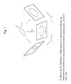
- the deformation method from Borrel and Bechmann which is illustrated in Figure 1, is based on the following principle: the original and deformed space R n are two projections of a higher dimensional space R m .
- the deformation is thus defined by the composition of a function f : R n ⁇ R m that transforms the points of the original space R n into points of R m with a projection T from R m back onto R n .
- the projection matrix is computed so as to achieve given displacements (called constraints) of given points (called constraints points) of the original space.
- this model encapsulates a large family of possible deformations: for example, linear space transformations are obtained if f is linear, or FFD are obtained if f is a tensor product Bernstein polynomial and if M is built with displacement vectors of control points.
- a radius is introduced which affects the scope of each B-spline, i.e., each basis function falls to zero beyond the radius of the corresponding constraint point.
- the different radii may be used for a fine-tuning of the deformation process. Consequently, a 'Scodef deformation can be viewed as the deformation obtained by creating an arbitrary number of possible overlapping B-spline-shaped ,,bumps,, over the space.
- the location and height of a bump are defined by a constraint and its width by the constraints radius of influence'.
- the constraints and/or the displacements of the constraints constitute the free parameters which may be modified with the help of ES-standard genetic operators.
- the radii associated with the n c constraint points V i may be used as additional design parameters.
- three groups of design parameters are available which make the technique very flexible in the number of design parameters.
- four constraint points are necessary for the deformation of a 3D object.
- triples of constraint points their displacements and radii can easily be added or deleted without influencing other design parameters.
- such an adaptation process can change the structure of the transformation matrix M and therefore the resulting design. This is in contrast to e.g., B-splines or NURBS where curve or surface preserving addition operators exist which in contrast force the recalculation of control points.
- FFD Free Form Deformation
- the first step of the FFD is the fixation of the local coordinate system S, T, U of the enclosing parallelepiped region.
- the next step is the formulation of a grid of control points P ijk on the parallelepiped.
- the l grid points in S direction, m points in T direction, and n points in U direction allow for the formulation of the deformed enclosing volume with the help of trivariate tensor product Bernstein polynomials whose control points are the grid points.
- the deformation of the control points which essentially build the free parameters for a potential design optimization is simply specified by moving the P ijk from their undisplaced lattice positions.
- X ffd is a vector containing the Cartesian coordinates of the displaced point
- each P ijk is a vector containing the Cartesian coordinates of the control points.
- a shape modification tool which is independent of the underlying geometric representation is of primary interest.
- a lattice of control points has to be constructed which encloses either the whole object or a part of the object which is targeted for being modified.
- the geometry coordinates have to be transferred into the spline coordinate system, which is also called "freezing".
- freezing object coordinates the u, v and w coordinates of the geometry in spline parameter space are calculated. This is usually done by Newton approximation which promises to be the fastest approach but it can also be done by similar gradient based methods or even by evolutionary optimisation.
- the deformations can be applied by moving the control points to the desired positions.
- the x, y and z coordinates of the surface or solid can be calculated by retransforming the object points from the spline coordinate system to the original used coordinate system. Therefore the B-spline equations have to be solved using the new spatial coordinates of the control points. This method is also valid if the geometry model equals a solid or is defined by parametric or implicit equations.
- EFFDs are quite effective for creating impressions, reliefs and other fairly simple deformations that might otherwise be difficult to achieve with FFDs.
- the user must know the general shape of the deformation before starting to model, and the interface is still a direct representation of the underlying mathematics.
- one aspect of the invention is to generate the transformation function f which is optimized to be able to realise desired changes of object parameters by means of control point variations.
- This optimisation can be realized in a way that the mapping between the original coordinate system of the design and the spline coordinate system is not changed, so that no additional “freezing” process (the generation of the mapping between the coordinate systems) is necessary.
- the optimisation loop can start the initial shape has to be embedded in the lattice(s) and the geometry has to be frozen to obtain the u, v and w-coordinates in parameter space.
- These coordinates play the major role in the genotype - phenotype mapping before the design evaluation step in the evolutionary optimisation.
- the mutation can be applied and the systems can be prepared for fitness evaluation. Therefore the new designs are calculated via B-spline or Nurbs equations based on the frozen u, v, w-coordinates coupled with the new control points. Afterwards the designs can be evaluated and the fitness values are assigned to each individual. Finally the new parameters are selected and the parents for the following generation are determined according to the chosen evolutionary algorithms.
- Free form deformations offer the possibility to extend the knot vectors by adding further control points without changing the actual shape in the design process. This fact is very important in an evolutionary design optimisation. One can start the optimisation with only quite a low number of parameters and, whenever needed, new control points can be added to extend the influence on the shape without losing the actual best design. Beside these very positive features of this representation the control point insertion is accompanied by one major disadvantage. Whenever new control points have to be inserted there only exists the possibility to introduce a whole new row or column of control points if two-dimensional or a plain of control points if three-dimensional into the control point grid. So unfortunately it is not possible to insert only one control point where it is directly needed for geometrical reasons but as a consequence many superfluous points have to be taken into account. To minimize this effect the concepts of T-splines are highlighted in follwoing which are a special kind of point-based B-splines allowing the insertion of only partial rows or columns of control points into the control mesh.
- T-splines as such is an already known representation e.g. for computer graphics.
- T-splines have been introduced by Sederberg et al.[1, 10] to achieve more flexibility in the process of graphical designing.
- T-splines are a generalisation of non-uniform B-splines surfaces offering an immense benefit in terms of specifying the arrangement of control points in the underlying mesh.
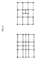
- a B-spline surface which require a rectangular grid of control points defined in each cross of a horizontal and vertical line the lines in a T-mesh need not to start and end on the edges of the grid but they can terminate in a T-junction (cf. Figure 4). As a consequence the total number of control points is reduced drastically.
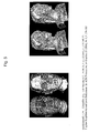
- Figure 5 illustrates the effect of transforming a NURBS model into T-splines.
- the total number of control points of the modeled head is reduced from 4712 to 1109 and from 10305 to 3955 for the woman respectively.
- the designer obtains a more efficient control on the models and movements of the position of single control points have a close influences on the shape.
- T-splines are not only valid for surface modelling in two-dimensional but they can be easily extended to other dimensions and to T-NURCCs (Non-Uniform Rational Catmull-Clark Surfaces) which is the arbitrary-topology version of T-splines [1,8, 10].
- a T-spline can be deduced from the so-called point-based B-splines (PB-splines), which are introduced by Sederberg et al. [10].
- PB-splines are defined by a set of control points and in two-dimensional a pair of knot vectors for each control point.
- the u i are the knots in the knot vector and p defines the degree of the spline.
- the weights w i can be chosen freely.
- T-spline In contrast to a general defined PB-spline a T-spline is structured by a so-called T-mesh which defines some order to the positions of control points.
- T-mesh An example of a T-mesh can be found in Figure 6.
- T-splines One major advantage of T-splines is the possibility to insert new control points at arbitrary positions in the T-mesh without the requirement to add a whole new row or column of control points.
- Sederberg et al. have developed a procedure containing rules and algorithms for successful knot insertion. The insertion process is done in two phases which are called topology and geometry phase. In the topology phase the control points which have to be inserted additionally are identified and in the geometry phase the new coordinates and weights for the new T-mesh are calculated.
- Sederberg et al. [8] state three possible violations which may occur during the insertion process and have to be corrected by inserting additional control points:
- T-splines offer a very good trade-off for this requirement in design optimisation.
- the parameters are set to the control points of the T-mesh. So one can start with a quite low number of control points and in the course of the optimisation control points can be added at any position to increase the resolution. So by application of this representation the high flexibility of T-splines can be used to position the control points directly where they are needed to achieve a maximum influence on the geometric shape while keeping the so-far best design. Because this will result in most cases to an addition of only a few control points the number of parameters is kept as low as possible. This affects the optimisation in a very positive way.
- the parameter of the transformation determines the degree of freedom for the modification the parameter has to be set in a way, that the necessary changes can be performed by the selected parameter.
- the "necessary changes, are not known beforehand and can only be based on experience.
- To generally increase the degree of freedom one could simply increase the number of control points in case of the free-form deformation. This would make the influence of the control points more local and global changes to the design are much more difficult to realize because various control points have to be changed simultaneously.
- Furthermore there is a trade-off between freedom for the modification and the dimensionality of the optimisation by changing the number of control points or the dimension of the matrix M in case of constrained deformations. This relation can also be observed representing curves or surfaces using splines.
- T-splines which is explained above is the reason for their development.
- a surface By representing a surface by a e.g. a NURBS surface spline the addition of a single control point requires the addition of a full row and or column of additional control points only to satisfy the constrains given by the representation. The same holds true when applying free form deformation methods which define the transformation of a design into another modified design.
- a spline e.g. a surface spline
- various methods exist to determine the optimal position of new control points in case of an approximation of a given surface.
- local and global approximation methods exist in order to find the optimal position for new control points.
- These methods are only applicable in case of the existence of a local quality measure.
- this local quality measure does not exist the methods cannot be applied. This is for example the case for quality measures which are based on aerodynamic properties of the represented body.
- the pressure loss is used as a quality measure. This pressure loss depends on the whole body of the design and it cannot be determined beforehand where additional control points have to be introduced.
- T-splines resolve this problem in case of the representation of surfaces.
- the use of T-splines instead of Nurbs splines allows for an introduction of single additional control points for that case.
- T-spline In the same way than for surface modeling the use of T-spline can solve the problem during control point addition for free form deformations.
- introduction of new control points can be realized by an additional mutation operator.
- the additional mutation operator modifies the representation of the transformation instead of the parameter of the transformation in the same way.
- the mechanism which allows the selection of optimal positions for the introduction of additional control points is the same then already explained.
- the difference and the advantage is that the method allows the local extension of the transformation function.
- Figure 7 shows on the left hand side a simplified configuration of a design object and a grid comprising an object point 710 and control points 720.
- the same configuration is shown with a chosen target point and derived control points.
- a targeted movement of the object point, as indicated by target point 730, and a corresponding alteration of the object, is to be achieved by deriving control points 740 in the grid, which are considered "optimal", e.g. in the sense of a close overall approximation of a desired shape.
- Figure 8 shows a flowchart of a method for optimising a design, wherein the object points are directly manipulated and the control points are chosen using an evolutionary algorithm. In step 810, one or several object points are chosen.
- the object points are manipulated directly, e.g. manually.
- the movement of the respective object point indicates a desired transformation of the design object.
- the grid representation is adapted or optimized in order to find the optimal control structure to represent the desired transformation. In one embodiment of the invention, this can be done by using evolutionary computation as described above.
- the control points may be encoded in a genome, inserting control points randomly, that is, at the same time adapting the chromosome and finally evaluating the new control structure or volume with respect to the targeted movement.
- stochastic optimization may be used instead of an evolutionary algorithm.
- the "best" among them can be chosen according to some fitness function and then checked whether the targeted object point movement is achieved. If not, the adaptation repeats.
- the adaptation of the control structure or volume may by achieved by a "hybrid” approach, that is, it may be globally guided by an evolutionary algorithm which is locally supplemented by e.g. least squares optimization.
- Figure 9 shows a flowchart of a method for optimising a design in which the set of chosen object points is optimised before the control structure or volume is adapted.
- object points are chosen by the user.
- the chosen set of object points is manipulated.
- An evolutionary strategy e.g. an evolutionary or a genetic algorithm may be used for this task, wherein the execution of the algorithm adapts the parameters of the object points.
- the adaptation of the subset of object points may comprise changing the number of object points, i.e. increasing or decreasing them, as in the flowchart (step 930).
- the control structure or volume i.e. the grid may adapted based on the object points using a least squares method or the method using evolutionary strategies described above (step 940).
- the algorithm shown in figure 9 combines the DFFD approach with stochastic optimization techniques, e.g. EAs.
- EAs stochastic optimization techniques
- This approach is straightforward.
- the object points which have been determined by the user are encoded in the parameter set of the optimizer and then the optimisation is performed.
- the targeted object points movements are tried to be achieved as best as possible.
- a number of object points is defined and an EA is run on these on these object points.
- the least squares algorithm in Hsu et. al. [3] or the structure optimization described above is run to adapt the FFD grid in such a way that the changes induced onto the geometry by the EA acting on the object points are realized.
- the representation may be changed, i.e. the number of object points may be increased or decreased.
- An evolutionary strategy may be used, e.g. a genetic algorithm.
- the representation (object points) may be re-sampled in each optimization step before changes to the object points are made using a stochastic optimization algorithm, e.g. an EA.
- EA stochastic optimization algorithm
- the least squares algorithm in [3] or the structure optimization described above may be run to adapt the FFD grid in such a way that the changes induced onto the geometry by the EA acting on the object points are realized.
- the control volume as proposed above to modify the control volume in such a way that the target object point positions can be realized.
- there are two optimisation algorithms working in the one global optimisation loop One modifies the object points encoded in the parameter set to optimize the shape and the second (internal) one adapts the control volume to realize the targeted shape.
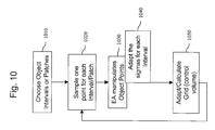
- Figure 10 shows an embodiment of the method for optimising a design in which object points are chosen from object intervals or patches.
- the object intervals or patches are chosen.
- the method samples one object point for each object interval or patch. Similar to the above, the chosen set of object points is then manipulated and adapted in step 1030.
- the sigma-values for the intervals i.e. the standard deviation, may be varied during the adaptation, in step 1040.
- the grid or control volume or structure is adapted or re-calculated in step 1050, based on the optimised object points. This may be done alternatively using a least squares approximation criterion or the method for adapting the grid described above.
- Figure 11 is another illustration of the principles realized by the method described in relation to figures 9 and 10.
- object intervals or patches are chosen.
- one object point is samples from each interval or patch.
- the object points are subsequently encoded in a parameter set, which is fed into the adaptation algorithm, e.g. an evolutionary or a genetic algorithm.
- the control volume is modified to achieve target object points movements.
- the control volume or structure is then optionally adapted to improve the targeted object points movements. If modifications are carried out in parallel, then the "best" modification may be selected using an optimality criterion and the iteration may be restarted.
- optimization has two handles to tweak in DFFD, e.g. the grid representation (as in FFD) and the optimization of object points - "the D part".
- the geometry may be divided in intervals or patches.
- a representation may be defined by the number of intervals or patches.
- One object point for each interval or patch may be re-sampled in each optimization step before changes to the object points are made using a stochastic optimization algorithm, e.g. an EA. Inside the EA loop the least squares algorithm in [3] or the structure optimization described above may be run to adapt the FFD grid in such a way that the changes induced onto the geometry by the EA acting on the object points are realized.
- the representation may be changed, i.e. the number of intervals/patches may be increased/decreased.
- An evolutionary strategy (ES) may be used to self-adapt one strategy parameter for each interval and/or patch.
- the explained methods are based on the known representation of designs using a basic design which is then modified by a transformation function.
- the transformation function is defined by a spline function which transforms the space in which the design is defined into a second space where the new modified design is defined.
- the parameter of the spline function determine the parameter of the transformation function.
- Evolution Strategies the parameter of the spline function determine at the same time the parameter the optimization algorithm works in.
- a mutation operator is proposed which allows to introduce and to delete control points. Instead of the standard mutation operator in evolution strategies this mutation operator works on the representation of the problem/design.
Landscapes
- Physics & Mathematics (AREA)
- Engineering & Computer Science (AREA)
- General Physics & Mathematics (AREA)
- Pure & Applied Mathematics (AREA)
- Mathematical Optimization (AREA)
- Mathematical Physics (AREA)
- Mathematical Analysis (AREA)
- Algebra (AREA)
- Computer Graphics (AREA)
- Geometry (AREA)
- Software Systems (AREA)
- Theoretical Computer Science (AREA)
- Image Generation (AREA)
- Processing Or Creating Images (AREA)
Priority Applications (4)
| Application Number | Priority Date | Filing Date | Title |
|---|---|---|---|
| EP06006293A EP1840841B1 (fr) | 2006-03-27 | 2006-03-27 | Manipulation directe évolutionnaire de représentations de déformation en forme libre pour l'optimisation graphique |
| DE602006002958T DE602006002958D1 (de) | 2006-03-27 | 2006-03-27 | Evolutionäre direkte Manipulation von Freiformdeformationsdarstellungen zur Designoptimierung |
| JP2007057357A JP4662959B2 (ja) | 2006-03-27 | 2007-03-07 | デザイン最適化のための自由形状変形(FreeFormDeformation)表現の進化的直接操作(EvolutionaryDirectManipulation) |
| US11/683,910 US8098244B2 (en) | 2006-03-27 | 2007-03-08 | Evolutionary direct manipulation of free form deformation representations for design optimization |
Applications Claiming Priority (1)
| Application Number | Priority Date | Filing Date | Title |
|---|---|---|---|
| EP06006293A EP1840841B1 (fr) | 2006-03-27 | 2006-03-27 | Manipulation directe évolutionnaire de représentations de déformation en forme libre pour l'optimisation graphique |
Publications (2)
| Publication Number | Publication Date |
|---|---|
| EP1840841A1 true EP1840841A1 (fr) | 2007-10-03 |
| EP1840841B1 EP1840841B1 (fr) | 2008-10-01 |
Family
ID=37232975
Family Applications (1)
| Application Number | Title | Priority Date | Filing Date |
|---|---|---|---|
| EP06006293A Ceased EP1840841B1 (fr) | 2006-03-27 | 2006-03-27 | Manipulation directe évolutionnaire de représentations de déformation en forme libre pour l'optimisation graphique |
Country Status (4)
| Country | Link |
|---|---|
| US (1) | US8098244B2 (fr) |
| EP (1) | EP1840841B1 (fr) |
| JP (1) | JP4662959B2 (fr) |
| DE (1) | DE602006002958D1 (fr) |
Cited By (2)
| Publication number | Priority date | Publication date | Assignee | Title |
|---|---|---|---|---|
| FR3023942A1 (fr) * | 2014-07-15 | 2016-01-22 | Inst Rech Technologique Systemx | Procede et systeme de conception de forme optimale d'un objet |
| US10339226B2 (en) | 2016-06-08 | 2019-07-02 | Ecole Polytechnique Federale De Lausanne (Epfl) | System and method for defining watertight and locally refinable surfaces with interpolatory control points |
Families Citing this family (18)
| Publication number | Priority date | Publication date | Assignee | Title |
|---|---|---|---|---|
| US8310481B2 (en) * | 2007-10-12 | 2012-11-13 | Edward Ernest Bailey | Computer aided design method for enhancement of local refinement through T-splines |
| JP4659060B2 (ja) * | 2008-04-21 | 2011-03-30 | 株式会社日立製作所 | 形状モデル作成装置及び形状フィッティングの最適化処理方法 |
| US9208132B2 (en) | 2011-03-08 | 2015-12-08 | The Nielsen Company (Us), Llc | System and method for concept development with content aware text editor |
| WO2012122431A1 (fr) | 2011-03-08 | 2012-09-13 | Affinnova, Inc. | Système et procédé pour le développement de concepts |
| US20120259676A1 (en) | 2011-04-07 | 2012-10-11 | Wagner John G | Methods and apparatus to model consumer choice sourcing |
| JP5635455B2 (ja) * | 2011-06-07 | 2014-12-03 | 本田技研工業株式会社 | 形状変形装置、形状変形方法及びプログラム |
| US8666119B1 (en) * | 2011-11-29 | 2014-03-04 | Lucasfilm Entertainment Company Ltd. | Geometry tracking |
| US9311383B1 (en) | 2012-01-13 | 2016-04-12 | The Nielsen Company (Us), Llc | Optimal solution identification system and method |
| EP2763058B1 (fr) * | 2013-01-30 | 2021-10-20 | Honda Research Institute Europe GmbH | Optimisation de la conception de structures/objets physiques |
| US9799041B2 (en) | 2013-03-15 | 2017-10-24 | The Nielsen Company (Us), Llc | Method and apparatus for interactive evolutionary optimization of concepts |
| US9785995B2 (en) | 2013-03-15 | 2017-10-10 | The Nielsen Company (Us), Llc | Method and apparatus for interactive evolutionary algorithms with respondent directed breeding |
| US10147108B2 (en) | 2015-04-02 | 2018-12-04 | The Nielsen Company (Us), Llc | Methods and apparatus to identify affinity between segment attributes and product characteristics |
| US11176741B2 (en) * | 2018-08-09 | 2021-11-16 | Autodesk, Inc. | Techniques for generating stylized quad-meshes from tri-meshes |
| CN115455588B (zh) * | 2022-08-29 | 2025-10-14 | 厦门大学 | 涡轮叶片精铸模具型面反变形设计方法 |
| CN116561903B (zh) * | 2023-03-13 | 2026-04-14 | 郑州轻工业大学 | 基于ffd自由变形方法的离心通风机叶型参数化方法 |
| US12608623B2 (en) * | 2023-07-06 | 2026-04-21 | GM Global Technology Operations LLC | Optimization for finite state machine modeled systems |
| CN116720265B (zh) * | 2023-08-09 | 2023-12-08 | 北京航空航天大学 | 一种基于变维度ffd的叶轮机的统一参数化方法及装置 |
| CN119397689B (zh) * | 2024-11-04 | 2025-08-15 | 哈尔滨工业大学 | 一种基于削弱尾缘激波的涡轮造型方法 |
Family Cites Families (10)
| Publication number | Priority date | Publication date | Assignee | Title |
|---|---|---|---|---|
| JP2762000B2 (ja) * | 1992-06-25 | 1998-06-04 | 株式会社日立製作所 | 曲面生成方法および曲面生成装置 |
| US5818452A (en) * | 1995-08-07 | 1998-10-06 | Silicon Graphics Incorporated | System and method for deforming objects using delta free-form deformation |
| US6608631B1 (en) * | 2000-05-02 | 2003-08-19 | Pixar Amination Studios | Method, apparatus, and computer program product for geometric warps and deformations |
| US7272541B2 (en) * | 2001-02-16 | 2007-09-18 | Dassault Systems | Method and system for generating and handling a harmonized network of points |
| EP1235180A1 (fr) * | 2001-02-26 | 2002-08-28 | Honda R&D Europe (Deutschland) GmbH | Adaptation de paramètres dans des stratégies évolutives |
| US7542036B2 (en) * | 2003-02-19 | 2009-06-02 | California Institute Of Technology | Level set surface editing operators |
| US7274364B2 (en) * | 2003-03-26 | 2007-09-25 | Brigham Young University | System and method for defining T-spline and T-NURCC surfaces using local refinements |
| US7596283B2 (en) * | 2004-04-12 | 2009-09-29 | Siemens Medical Solutions Usa, Inc. | Fast parametric non-rigid image registration based on feature correspondences |
| WO2006048875A2 (fr) * | 2004-11-05 | 2006-05-11 | Yissum Research Development Company Of The Hebrew University Of Jerusalem | Procede et systeme pour deformation video spatio-temporelle |
| EP1675068B1 (fr) * | 2004-12-27 | 2014-03-12 | Honda Research Institute Europe GmbH | Optimisation évolutive et déformation de formes libres |
-
2006
- 2006-03-27 DE DE602006002958T patent/DE602006002958D1/de not_active Expired - Lifetime
- 2006-03-27 EP EP06006293A patent/EP1840841B1/fr not_active Ceased
-
2007
- 2007-03-07 JP JP2007057357A patent/JP4662959B2/ja not_active Expired - Fee Related
- 2007-03-08 US US11/683,910 patent/US8098244B2/en not_active Expired - Fee Related
Non-Patent Citations (4)
| Title |
|---|
| GANG ZHAO ET AL: "Detail-preserving variational design of B-spline curves and surfaces", CYBERWORLDS, 2003. PROCEEDINGS. 2003 INTERNATIONAL CONFERENCE ON 3-5 DEC. 2003, PISCATAWAY, NJ, USA,IEEE, 3 December 2003 (2003-12-03), pages 206 - 213, XP010674968, ISBN: 0-7695-1922-9 * |
| HSU W M ET AL: "DIRECT MANIPULATION OF FREE-FORM DEFORMATIONS", COMPUTER GRAPHICS, NEW YORK, NY, US, vol. 26, no. 2, July 1992 (1992-07-01), pages 177 - 184, XP008011515, ISSN: 0097-8930 * |
| MENZEL S ET AL: "Application of Free Form Deformation Techniques in Evolutionary Design Optimisation", INTERNET CITATION, 30 May 2005 (2005-05-30), XP002375170, Retrieved from the Internet <URL:http://www.wcsm06.org/papers/5161.pdf> [retrieved on 20060331] * |
| SEDERBERG T W ET AL: "T-Splines and T-NURCCs", ACM TRANSACTIONS ON GRAPHICS, ACM, NEW YORK, NY, US, vol. 22, no. 3, July 2003 (2003-07-01), pages 477 - 478, XP002990565, ISSN: 0730-0301 * |
Cited By (2)
| Publication number | Priority date | Publication date | Assignee | Title |
|---|---|---|---|---|
| FR3023942A1 (fr) * | 2014-07-15 | 2016-01-22 | Inst Rech Technologique Systemx | Procede et systeme de conception de forme optimale d'un objet |
| US10339226B2 (en) | 2016-06-08 | 2019-07-02 | Ecole Polytechnique Federale De Lausanne (Epfl) | System and method for defining watertight and locally refinable surfaces with interpolatory control points |
Also Published As
| Publication number | Publication date |
|---|---|
| US20070222793A1 (en) | 2007-09-27 |
| EP1840841B1 (fr) | 2008-10-01 |
| JP2007265401A (ja) | 2007-10-11 |
| JP4662959B2 (ja) | 2011-03-30 |
| US8098244B2 (en) | 2012-01-17 |
| DE602006002958D1 (de) | 2008-11-13 |
Similar Documents
| Publication | Publication Date | Title |
|---|---|---|
| US8098244B2 (en) | Evolutionary direct manipulation of free form deformation representations for design optimization | |
| Ruuth et al. | A simple embedding method for solving partial differential equations on surfaces | |
| Shephard et al. | Automatic three‐dimensional mesh generation by the finite octree technique | |
| Löhner | Automatic unstructured grid generators | |
| RU2519331C2 (ru) | Способ вычисления физического значения, способ численного анализа, программа вычисления физического значения, программа численного анализа, устройство вычисления физического значения и устройство численного анализа | |
| US7643026B2 (en) | NURBS surface deformation apparatus and the method using 3D target curve | |
| KR101627373B1 (ko) | 가이딩 곡선들에 의해 정의된 표면들의 설계의 컴퓨터 구현 방법 | |
| US7982732B2 (en) | Evolutionary design optimization using extended direct manipulation of free form deformations | |
| JP2004127099A (ja) | Cadシステム及びcadプログラム | |
| CN116910834B (zh) | 基于nurbs曲面快速求交算法的cad模型构建方法 | |
| EP1675068B1 (fr) | Optimisation évolutive et déformation de formes libres | |
| US6693631B2 (en) | System and method for multi-resolution fairing of non-manifold models | |
| JP2003030172A (ja) | 拘束条件付き最適化方法及びプログラム | |
| Jung et al. | Tetrahedron-based octree encoding for automatic mesh generation | |
| EP2442279B1 (fr) | Optimisation de la conception de corps physiques | |
| JP2920195B2 (ja) | 形状変換方法及び装置 | |
| CN119129183B (zh) | 一种基于bvh与平方和规划的三维cad模型碰撞检测方法 | |
| Bigot et al. | Capture of 3D moving free surfaces and material interfaces by mesh deformation | |
| JP7645484B2 (ja) | 情報処理方法及び情報処理装置 | |
| Urick et al. | Reconstruction of trimmed NURBS surfaces for gap-free intersections | |
| JP3787748B2 (ja) | 数値解析用メッシュ作成装置 | |
| Sahoo et al. | A composite adaptive grid generation and migration technique for materials processing problems | |
| Brakhage et al. | CAGD tools for high quality grid generation and sparse representation | |
| Rypl et al. | Triangulation of 3D surfaces recovered from STL grids | |
| Gregorski et al. | Adaptive contouring with quadratic tetrahedra |
Legal Events
| Date | Code | Title | Description |
|---|---|---|---|
| PUAI | Public reference made under article 153(3) epc to a published international application that has entered the european phase |
Free format text: ORIGINAL CODE: 0009012 |
|
| AK | Designated contracting states |
Kind code of ref document: A1 Designated state(s): AT BE BG CH CY CZ DE DK EE ES FI FR GB GR HU IE IS IT LI LT LU LV MC NL PL PT RO SE SI SK TR |
|
| AX | Request for extension of the european patent |
Extension state: AL BA HR MK YU |
|
| 17P | Request for examination filed |
Effective date: 20071116 |
|
| GRAP | Despatch of communication of intention to grant a patent |
Free format text: ORIGINAL CODE: EPIDOSNIGR1 |
|
| AKX | Designation fees paid |
Designated state(s): DE FR GB |
|
| GRAS | Grant fee paid |
Free format text: ORIGINAL CODE: EPIDOSNIGR3 |
|
| GRAA | (expected) grant |
Free format text: ORIGINAL CODE: 0009210 |
|
| AK | Designated contracting states |
Kind code of ref document: B1 Designated state(s): DE FR GB |
|
| REG | Reference to a national code |
Ref country code: GB Ref legal event code: FG4D |
|
| REF | Corresponds to: |
Ref document number: 602006002958 Country of ref document: DE Date of ref document: 20081113 Kind code of ref document: P |
|
| PLBE | No opposition filed within time limit |
Free format text: ORIGINAL CODE: 0009261 |
|
| STAA | Information on the status of an ep patent application or granted ep patent |
Free format text: STATUS: NO OPPOSITION FILED WITHIN TIME LIMIT |
|
| 26N | No opposition filed |
Effective date: 20090702 |
|
| REG | Reference to a national code |
Ref country code: DE Ref legal event code: R084 Ref document number: 602006002958 Country of ref document: DE Effective date: 20140711 |
|
| REG | Reference to a national code |
Ref country code: GB Ref legal event code: 746 Effective date: 20150330 |
|
| REG | Reference to a national code |
Ref country code: FR Ref legal event code: PLFP Year of fee payment: 11 |
|
| REG | Reference to a national code |
Ref country code: FR Ref legal event code: PLFP Year of fee payment: 12 |
|
| REG | Reference to a national code |
Ref country code: FR Ref legal event code: PLFP Year of fee payment: 13 |
|
| PGFP | Annual fee paid to national office [announced via postgrant information from national office to epo] |
Ref country code: FR Payment date: 20190326 Year of fee payment: 14 Ref country code: GB Payment date: 20190325 Year of fee payment: 14 Ref country code: DE Payment date: 20190328 Year of fee payment: 14 |
|
| REG | Reference to a national code |
Ref country code: DE Ref legal event code: R119 Ref document number: 602006002958 Country of ref document: DE |
|
| PG25 | Lapsed in a contracting state [announced via postgrant information from national office to epo] |
Ref country code: DE Free format text: LAPSE BECAUSE OF NON-PAYMENT OF DUE FEES Effective date: 20201001 Ref country code: FR Free format text: LAPSE BECAUSE OF NON-PAYMENT OF DUE FEES Effective date: 20200331 |
|
| GBPC | Gb: european patent ceased through non-payment of renewal fee |
Effective date: 20200327 |
|
| PG25 | Lapsed in a contracting state [announced via postgrant information from national office to epo] |
Ref country code: GB Free format text: LAPSE BECAUSE OF NON-PAYMENT OF DUE FEES Effective date: 20200327 |