EP1840873A1 - Audiosignalkodierverfahren, Programm des Audiosignalkodierverfahrens, Aufzeichnungsmedium, auf dem das Programm des Audiosignalkodierverfahrens aufgezeichnet ist, und Audiosignalkodiervorrichtung - Google Patents
Audiosignalkodierverfahren, Programm des Audiosignalkodierverfahrens, Aufzeichnungsmedium, auf dem das Programm des Audiosignalkodierverfahrens aufgezeichnet ist, und Audiosignalkodiervorrichtung Download PDFInfo
- Publication number
- EP1840873A1 EP1840873A1 EP07006188A EP07006188A EP1840873A1 EP 1840873 A1 EP1840873 A1 EP 1840873A1 EP 07006188 A EP07006188 A EP 07006188A EP 07006188 A EP07006188 A EP 07006188A EP 1840873 A1 EP1840873 A1 EP 1840873A1
- Authority
- EP
- European Patent Office
- Prior art keywords
- bits
- bit allocation
- subband
- evaluation criterion
- audio signal
- Prior art date
- Legal status (The legal status is an assumption and is not a legal conclusion. Google has not performed a legal analysis and makes no representation as to the accuracy of the status listed.)
- Granted
Links
Images








Classifications
-
- G—PHYSICS
- G10—MUSICAL INSTRUMENTS; ACOUSTICS
- G10L—SPEECH ANALYSIS TECHNIQUES OR SPEECH SYNTHESIS; SPEECH RECOGNITION; SPEECH OR VOICE PROCESSING TECHNIQUES; SPEECH OR AUDIO CODING OR DECODING
- G10L19/00—Speech or audio signals analysis-synthesis techniques for redundancy reduction, e.g. in vocoders; Coding or decoding of speech or audio signals, using source filter models or psychoacoustic analysis
- G10L19/02—Speech or audio signals analysis-synthesis techniques for redundancy reduction, e.g. in vocoders; Coding or decoding of speech or audio signals, using source filter models or psychoacoustic analysis using spectral analysis, e.g. transform vocoders or subband vocoders
- G10L19/0204—Speech or audio signals analysis-synthesis techniques for redundancy reduction, e.g. in vocoders; Coding or decoding of speech or audio signals, using source filter models or psychoacoustic analysis using spectral analysis, e.g. transform vocoders or subband vocoders using subband decomposition
-
- G—PHYSICS
- G10—MUSICAL INSTRUMENTS; ACOUSTICS
- G10L—SPEECH ANALYSIS TECHNIQUES OR SPEECH SYNTHESIS; SPEECH RECOGNITION; SPEECH OR VOICE PROCESSING TECHNIQUES; SPEECH OR AUDIO CODING OR DECODING
- G10L19/00—Speech or audio signals analysis-synthesis techniques for redundancy reduction, e.g. in vocoders; Coding or decoding of speech or audio signals, using source filter models or psychoacoustic analysis
- G10L19/02—Speech or audio signals analysis-synthesis techniques for redundancy reduction, e.g. in vocoders; Coding or decoding of speech or audio signals, using source filter models or psychoacoustic analysis using spectral analysis, e.g. transform vocoders or subband vocoders
-
- G—PHYSICS
- G10—MUSICAL INSTRUMENTS; ACOUSTICS
- G10L—SPEECH ANALYSIS TECHNIQUES OR SPEECH SYNTHESIS; SPEECH RECOGNITION; SPEECH OR VOICE PROCESSING TECHNIQUES; SPEECH OR AUDIO CODING OR DECODING
- G10L19/00—Speech or audio signals analysis-synthesis techniques for redundancy reduction, e.g. in vocoders; Coding or decoding of speech or audio signals, using source filter models or psychoacoustic analysis
- G10L19/002—Dynamic bit allocation
-
- H—ELECTRICITY
- H03—ELECTRONIC CIRCUITRY
- H03M—CODING; DECODING; CODE CONVERSION IN GENERAL
- H03M7/00—Conversion of a code where information is represented by a given sequence or number of digits to a code where the same, similar or subset of information is represented by a different sequence or number of digits
- H03M7/30—Compression; Expansion; Suppression of unnecessary data, e.g. redundancy reduction
Definitions
- the present invention contains subject matter related to Japanese Patent Application JP 2006-086927 filed in the Japan Patent Office on March 28, 2006, the entire contents of which being incorporated herein by reference.
- the present invention is for example applicable to cases where audio signals are encoded by Layer 1 and Layer 2 of MPEG (Moving Picture Experts Group) 1 and MPEG2.
- the present invention reduces the load of processing as compared with a example in the past when an audio signal is encoded on the basis of psychoacoustic analysis, by sorting evaluation criteria for bit allocation in advance, detecting a subband signal to which to allocate bits, and when sorting a recalculated evaluation criterion, partly changing the sequence of a latest sort result, thereby sorting the evaluation criterion.
- perceptual coding is known as an audio signal encoding process.
- Perceptual coding is referred to also as psychoacoustic coding.
- Perceptual coding encodes an audio signal while not allocating bits to a component difficult to perceive on the basis of a minimum audible limit and a masking effect, and thus efficiently encodes the audio signal using characteristics of a human auditory sense.
- Layer 1 and Layer 2 of MPEG1 and MPEG2 are widely known as an encoding method using the technology of perceptual coding.
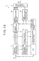
- FIG. 16 is a block diagram showing an encoder for encoding an audio signal S1.
- This encoder 1 is formed by a digital signal processor, for example.
- the encoder 1 encodes the audio signal S1 by Layer 1 or Layer 2 of MPEG1 or Layer 1 or Layer 2 of MPEG2, and then outputs a bit stream S2.
- the audio signal S1 is an audio signal of a plurality of channels, and is for example linearly quantized 16-bit PCM (Pulse Code Modulation) data or linearly quantized 24-bit PCM data.
- PCM Pulse Code Modulation
- a subband analyzing filter bank 2 in the encoder 1 is formed by a polyphase filter bank, for example.
- the subband analyzing filter bank 2 divides the overall frequency band of the audio signal S1 into 32 frequency bands (subbands), subsamples signals in the respective bands, and then outputs subband signals.
- subbands frequency bands
- subbands subsamples signals in the respective bands
- subband signals outputs subband signals.
- 384 samples of the audio signal S1 are set and processed in one frame
- 1152 samples of the audio signal S1 are set and processed in one frame.
- a linear quantizer 3 quantizes the subband signals output from the subband analyzing filter bank 2 under control of a dynamic bit allocation unit 4, and then outputs the quantized subband signals.
- a bit compressing unit 11 bit-compresses the output data of the linear quantizer 3, and then outputs the bit-compressed data.
- a bit stream forming unit 5 adds output data of a side information coding unit 10, CRC (Cyclic Redundancy Check) code, and the like to the output data of the bit compressing unit 11, and then outputs a bit stream S2.
- CRC Cyclic Redundancy Check
- a scale factor extracting unit 6 detects a scale factor for each subband signal output from the subband analyzing filter bank 2.
- the scale factor is a coefficient indicating a maximum value of amplitude of each subband signal.
- the scale factor extracting unit 6 sets 12 samples of each subband signal as one block, and detects a maximum value from absolute values of respective sample values of the subband signal for each block.
- the scale factor extracting unit 6 selects scale factors indicating amplitude values higher than the detected maximum value, and selects a scale factor indicating a minimum amplitude value from the selected scale factors.
- Layer 2 on the other hand, as in Layer 1, 12 samples are set as one block, and a scale factor is detected for each block. In addition, differences between the detected scale factors of successive blocks are detected, a successive pattern of the differences is represented by a transmission pattern of one to three bits, and the transmission pattern is output together with scale factor selection information 7. In Layer 2, the scale factor selection information 7 and the transmission pattern of one to three bits are transmitted as the scale factor of each block.
- a fast Fourier transform (FFT) unit 8 subjects the audio signal S1 in units of 512 samples in Layer 1 and in units of 1024 samples in Layer 2 to a fast Fourier transform process.
- a psychoacoustic model unit 9 calculates an SMR (Signal to Mask Ratio) for each subband from a result of the process of the fast Fourier transform unit 8 and the scale factor detected by the scale factor extracting unit 6, using a predetermined psychoacoustic model.
- the SMR is an evaluation value of each subband signal obtained from each subband signal to derive an evaluation criterion used for bit allocation to each subband signal.
- the SMR is a ratio (signal to mask ratio) between the maximum amplitude level of a subband signal and a maximum amplitude level masked by auditory or perceptual characteristics of a human (masking threshold value).
- the dynamic bit allocation unit 4 calculates an amount of bits allocatable for transmission of the audio signal S1 itself, and calculates an amount of bits to be allocated to each subband from the calculated amount of bits on the basis of the SMR. In addition, the dynamic bit allocation unit 4 calculates the quantization scale of each subband signal. The dynamic bit allocation unit 4 controls the linear quantizer 3 to encode each subband signal with the calculated amount of bits to be allocated and the calculated quantization scale. Incidentally, the amount of bits allocatable for the transmission of the audio signal S1 itself is obtained by subtracting a header, CRC code, ancillary data, and bit allocation data from a total number of useable bits.
- the side information coding unit 10 receives the amount of bits allocated to each subband signal, quantization scale data, scale factor data and the like as input data necessary for decoding, encodes the input data, and then outputs the result to the bit stream forming unit 5.
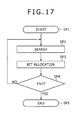
- FIG. 17 is a flowchart representing in brief the process of the dynamic bit allocation unit 4.
- the dynamic bit allocation unit 4 performs this processing procedure for each block of the audio signal S1.
- the dynamic bit allocation unit 4 calculates an MNR (Mask to Noise Ratio) of each subband signal from the SMR calculated in the psychoacoustic model unit 9.
- the MNR is an evaluation criterion for allocating bits to each subband signal.
- the MNR is obtained by subtracting the SMR [dB] from an SNR (Signal to Noise Ratio) [dB].
- the SNR is the SNR of each subband signal when quantization is performed with n bits, for example. Since no bits are allocated to each subband signal immediately after the process of FIG. 17 is started, an initial value is applied to n.
- step SP2 the dynamic bit allocation unit 4 searches the MNR of each subband signal to detect an MNR having a lowest value.
- the dynamic bit allocation unit 4 calculates an amount of bits to be allocated to a subband signal having the detected MNR, and allocates the calculated amount of bits to the subband signal.
- step SP4 the dynamic bit allocation unit 4 determines whether allocation of all allocatable bits is completed. When a negative result is obtained in step SP4, the dynamic bit allocation unit 4 recalculates the MNR of the subband signal to which the bits are allocated in step SP3. The dynamic bit allocation unit 4 then returns to step SP2. When a positive result is obtained in step SP4, on the other hand, the dynamic bit allocation unit 4 proceeds from step SP4 to step SP5 to end the processing procedure.
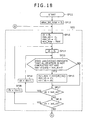
- FIG. 18 and FIG. 19 are flowcharts representing in detail the processing procedure of FIG. 17. Incidentally, although the process of step SP4 is performed after step SP3 in FIG. 17, FIG. 17 describes the processing procedure for convenience in order to facilitate understanding. In practice, as shown in FIG. 18 and FIG. 19, the processes corresponding to step SP3 and step SP4 are provided in order opposite to that of the example of FIG. 17.
- the dynamic bit allocation unit 4 calculates an MNR for each subband signal.
- the dynamic bit allocation unit 4 proceeds from step SP11 to step SP12, where the dynamic bit allocation unit 4 initializes a total number of bits allocation of which has been completed (alloc bit total) to a value 0.
- step SP13 the dynamic bit allocation unit 4 initializes various variables.
- ch is a variable for identifying a channel of the audio signal S1.
- min ch and min sb are variables for identifying a channel and a subband signal, respectively, of an MNR having a minimum value.
- min mnr is the minimum value of the MNR.
- the dynamic bit allocation unit 4 initializes ch to a value 0, min ch and min sb to a value -1, and min mnr to a maximum value MAX of possible values.
- the dynamic bit allocation unit 4 in step SP14 initializes a variable sb for identifying a subband signal to a value 0.
- the dynamic bit allocation unit 4 determines whether bit allocation to a subband signal (used[ch][sb]) identified by the variable sb for the channel identified by the variable ch is not completed yet and whether the value of the MNR of the subband signal is lower than the value of the variable min mnr.
- a case where it is determined that bit allocation to the subband signal (used[ch][sb]) identified by the variable sb for the channel identified by the variable ch is not completed yet is a case where the total number of bits allocation of which has been completed (alloc bit total) exceeds a total number of allocatable bits (total bit), or a case where the number of bits allocated to the subband signal exceeds the number of bits allocatable to one subband signal.
- the total number of bits allocation of which has been completed (alloc bit total) exceeds a total number of allocatable bits (total bit)
- step SP15 the dynamic bit allocation unit 4 updates the minimum MNR value min mnr to the MNR of the channel and the subband signal identified by the variables ch and sb.
- step SP16 the dynamic bit allocation unit 4 updates the variable min ch for identifying the channel having the minimum MNR value by the variable ch.
- step SP sb the dynamic bit allocation unit 4 updates the variable min sb for identifying the subband signal having the minimum MNR value by the variable sb.
- the dynamic bit allocation unit 4 then proceeds to step SP17.
- step SP15 When a negative result is obtained in step SP15, on the other hand, the dynamic bit allocation unit 4 directly proceeds from step SP15 to step SP17.
- step SP17 the dynamic bit allocation unit 4 determines whether the value of the variable sb is lower than the value of a total number of subbands (last sb). When a positive result is obtained in step SP17, the dynamic bit allocation unit 4 proceeds to step SP18, where the dynamic bit allocation unit 4 increments the variable sb by a value of one to change the subband signal as processing object to a following subband signal. The dynamic bit allocation unit 4 then returns to step SP15.
- step SP17 When a negative result is obtained in step SP17, on the other hand, the dynamic bit allocation unit 4 proceeds from step SP17 to step SP19.
- step SP19 the dynamic bit allocation unit 4 determines whether the value of the variable ch is lower than the value of a total number of channels (last ch). When a positive result is obtained in step SP19, the dynamic bit allocation unit 4 proceeds to step SP20, where the dynamic bit allocation unit 4 increments the variable ch by a value of one to change the channel as processing object to a following channel. The dynamic bit allocation unit 4 then returns to step SP14.
- the dynamic bit allocation unit 4 sequentially changes the channel and the subband signal, and detects a minimum MNR value, thus performing the process of step SP2 described above with reference to FIG. 17.
- a positive result is obtained in step SP19.
- the dynamic bit allocation unit 4 proceeds from step SP19 to step SP21 (FIG. 19).
- step SP21 the dynamic bit allocation unit 4 determines whether the variable min sb for identifying the subband signal having the minimum MNR value is maintained at the initial value (-1). When the variable min sb is maintained at the initial value (-1), a negative result is obtained in step SP15 for all the subband signals of all the channels. In this case, the dynamic bit allocation unit 4 proceeds from step SP21 to step SP22, where the dynamic bit allocation unit 4 ends the processing procedure.
- step SP21 and step SP22 correspond to step SP3 and step SP4 described above with reference to FIG. 17.
- step SP21 When a negative result is obtained in step SP21, on the other hand, the dynamic bit allocation unit 4 proceeds from step SP21 to step SP23.
- step SP23 the dynamic bit allocation unit 4 calculates the number of bits (alloc bit) to be allocated to the subband signal identified by the variable min sb for the channel identified by the variable min ch.
- the dynamic bit allocation unit 4 adds the number of bits (alloc bit) calculated in step SP23 to the total number of bits allocation of which has been completed so far (alloc bit total), and determines whether an addition value (alloc bit total + alloc bit) is lower than the total number of allocatable bits (total bit).
- step SP24 the dynamic bit allocation unit 4 proceeds to step SP25, where the dynamic bit allocation unit 4 sets the addition value (alloc bit total + alloc bit) as the total number of bits allocation of which is completed (alloc bit total).
- the dynamic bit allocation unit 4 increases the number of bits assigned to the subband signal identified by the variable min sb for the channel identified by the variable min ch by the number of bits calculated in step SP23, and reduces quantization steps for the subband signal identified by the variable min sb for the channel identified by the variable min ch by one step. Further, the dynamic bit allocation unit 4 recalculates the MNR of this subband signal, and reduces the number of bits assigned to the subband signal by a value of one.
- step SP26 the dynamic bit allocation unit 4 determines whether the number of bits already allocated to the subband signal exceeds the number of bits allocatable to one subband signal.
- step SP27 the dynamic bit allocation unit 4 sets the subband signal in a state of bit allocation being completed. The dynamic bit allocation unit 4 then returns to step SP13.
- step SP24 the dynamic bit allocation unit 4 proceeds from step SP24 to step SP27, where the dynamic bit allocation unit 4 sets the subband signal in a state of bit allocation being completed. The dynamic bit allocation unit 4 then returns to step SP13.
- steps SP23 to SP27 the dynamic bit allocation unit 4 allocates bits to the subband signal having the minimum MNR value detected by the process of steps SP13 to SP20.
- steps SP23 to SP27 correspond to step SP4 in FIG. 17.
- the present invention has been made in view of the above, and it is desirable to provide an audio signal encoding method, a program of the audio signal encoding method, a recording medium having the program of the audio signal encoding method recorded thereon, and an audio signal encoding device that can reduce the load of processing as compared with an existing example when an audio signal is encoded on the basis of psychoacoustic analysis.
- an audio signal encoding method for dividing an audio signal into a plurality of subband signals, allocating bits to the subband signals on a basis of psychoacoustic analysis, and encoding the audio signal
- the audio signal encoding method including the steps of: calculating evaluation criteria for allocating bits for each subband signal on the basis of the psychoacoustic analysis; sorting the evaluation criteria; and allocating the bits to the plurality of subband signals by repeating a bit allocating step, an evaluation criterion recalculating step, and a re-sorting step.
- the bit allocating step is a step of selecting one subband signal from the plurality of subband signals and allocating bits to the subband signal on a basis of one of a sort result of the sorting step and a sort result of the re-sorting step
- the evaluation criterion recalculating step is a step of recalculating the evaluation criterion of the subband signal to which the bits are allocated in the bit allocating step
- the re-sorting step is a step of applying the evaluation criterion calculated in the evaluation criterion recalculating step to the corresponding subband signal and sorting the evaluation criterion
- the re-sorting step sorts the evaluation criterion by partly changing a sequence of the sort result used for bit allocation in the bit allocating step that immediately precedes.
- a program of an audio signal encoding method the audio signal encoding method dividing an audio signal into a plurality of subband signals, allocating bits to the subband signals on a basis of psychoacoustic analysis, and encoding the audio signal
- the program being executed by arithmetic processing means, the program including the steps of: calculating evaluation criteria for allocating bits for each subband signal on the basis of the psychoacoustic analysis; sorting the evaluation criteria; and allocating the bits to the plurality of subband signals by repeating a bit allocating step, an evaluation criterion recalculating step, and a re-sorting step.
- the bit allocating step is a step of selecting one subband signal from the plurality of subband signals and allocating bits to the subband signal on a basis of one of a sort result of the sorting step and a sort result of the re-sorting step
- the evaluation criterion recalculating step is a step of recalculating the evaluation criterion of the subband signal to which the bits are allocated in the bit allocating step
- the re-sorting step is a step of applying the evaluation criterion calculated in the evaluation criterion recalculating step to the corresponding subband signal and sorting the evaluation criterion
- the re-sorting step sorts the evaluation criterion by partly changing a sequence of the sort result used for bit allocation in the bit allocating step that immediately precedes.
- a recording medium on which a program of an audio signal encoding method is recorded, the audio signal encoding method dividing an audio signal into a plurality of subband signals, allocating bits to the subband signals on a basis of psychoacoustic analysis, and encoding the audio signal, the program being executed by arithmetic processing means, the program including the steps of: calculating evaluation criteria for allocating bits for each subband signal on the basis of the psychoacoustic analysis; sorting the evaluation criteria; and allocating the bits to the plurality of subband signals by repeating a bit allocating step, an evaluation criterion recalculating step, and a re-sorting step.
- the bit allocating step is a step of selecting one subband signal from the plurality of subband signals and allocating bits to the subband signal on a basis of one of a sort result of the sorting step and a sort result of the re-sorting step
- the evaluation criterion recalculating step is a step of recalculating the evaluation criterion of the subband signal to which the bits are allocated in the bit allocating step
- the re-sorting step is a step of applying the evaluation criterion calculated in the evaluation criterion recalculating step to the corresponding subband signal and sorting the evaluation criterion
- the re-sorting step sorts the evaluation criterion by partly changing a sequence of the sort result used for bit allocation in the bit allocating step that immediately precedes.
- an audio signal encoding device for dividing an audio signal into a plurality of subband signals, allocating bits to the subband signals on a basis of psychoacoustic analysis, and encoding the audio signal.
- evaluation criteria for allocating bits are calculated for each subband signal on the basis of the psychoacoustic analysis; the evaluation criteria are subject to a sort; the bits are allocated to the plurality of subband signals by repeating bit allocation, evaluation criterion recalculation, and a re-sort; in the bit allocation, one subband signal is selected from the plurality of subband signals and bits are allocated to the subband signal on a basis of one of a sort result of the sort and a sort result of the re-sort; in the evaluation criterion recalculation, the evaluation criterion of the subband signal to which the bits are allocated in the bit allocation is recalculated; in the re-sort, the evaluation criterion calculated in the evaluation
- evaluation criteria for bit allocation are sorted in advance and a subband signal to which to allocate bits is detected.
- the evaluation criterion can be sorted by partly changing the sequence of a latest sort result. It is therefore possible to detect a subband signal to which to allocate bits by a simpler process as compared with the existing example.
- the load of processing can be reduced as compared with the existing example.
- the load of processing can be reduced as compared with the existing example.
- FIG. 1 is a flowchart of a processing procedure of a dynamic bit allocation unit 4 in an encoder according to a first embodiment of the present invention, for comparison with FIG. 17.
- the encoder according to the first embodiment is formed in the same manner as the encoder described above with reference to FIG. 16 except for the different processing procedure of the dynamic bit allocation unit 4 in the encoder according to the first embodiment. Therefore the following description will be made using the configuration of FIG. 16 as appropriate.
- the dynamic bit allocation unit 4 performs the processing procedure for each block set in an audio signal S1, and thereby assigns bits to each subband signal. Starting this processing procedure, as described above with reference to FIG. 17, the dynamic bit allocation unit 4 calculates the MNR of each subband signal. The dynamic bit allocation unit 4 then proceeds from step SP41 to step SP42, where the dynamic bit allocation unit 4 sorts the calculated MNRs in increasing order.
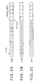
- the dynamic bit allocation unit 4 secures a certain area in a not shown memory, sorts combinations each including an MNR (p mnr (FIG. 2B)), an index index (FIG. 2A) for identifying a channel and a subband signal for which the MNR is detected, and a status used (FIG. 2C) indicating a status of processing for the index index for all subband signals of all channels by MNR, and then stores the result in the memory.
- the value 0 of the status (used) indicates a state in which no bits are allocated; the value 1 of the status (used) indicates a state in which bits are being allocated; and the value 2 of the status (used) indicates a state in which bit allocation is completed.
- the certain area is set to have a sufficient free space to store the combinations each including an index index, a status used, and an MNR for all the subband signals of all the channels and repeat the process of step SP44 to be described later.
- a combination of an MNR recorded in the memory, an index index for identifying a channel and a subband signal for which the MNR is detected, and a status used indicating a status of processing for the index index will hereinafter be referred to as an MNR combination as appropriate.
- the variable no identifies the MNR combination.
- step SP43 the dynamic bit allocation unit 4 detects an MNR having a lowest value recorded at the head of a sort result.
- the dynamic bit allocation unit 4 allocates bits to the subband signal of a corresponding channel, and then recalculates the MNR of the subband signal to which the bits are allocated.
- step SP44 the dynamic bit allocation unit 4 determines whether the allocation of all allocatable bits is completed.
- step SP45 the dynamic bit allocation unit 4 applies the MNR recalculated in step SP44 to re-sort the MNRs recorded in the memory.
- the dynamic bit allocation unit 4 sorts the MNRs by partially changing a sequence of a sort result so far. Specifically, the dynamic bit allocation unit 4 sequentially moves combinations of the sort result so far to an end side as indicated by arrows in the memory where the sort result is recorded until an MNR having a value lower than the recalculated MNR is detected. When an MNR having a value lower than the recalculated MNR is detected, the dynamic bit allocation unit 4 records a combination including the recalculated MNR in a free space obtained by moving the combinations.
- the dynamic bit allocation unit 4 excludes the record including the MNR before the recalculation from objects for subsequent processing.
- step SP45 the dynamic bit allocation unit 4 returns to step SP43, where the dynamic bit allocation unit 4 detects an MNR having a lowest value recorded at the head of the processing objects from the sort result obtained by the sorting in step SP45.
- FIGS. 4A, 4B, and 4C FIGS.
- the dynamic bit allocation unit 4 omits the process of step SP45 and repeats the process of step SP43.
- FIG. 5 is a flowchart representing details of step SP42 in the processing procedure of FIG. 1 together with related processes.
- the dynamic bit allocation unit 4 calculates an MNR for each subband signal when quantization is performed with one bit, for example.
- the dynamic bit allocation unit 4 then proceeds from step SP51 to step SP52.
- the dynamic bit allocation unit 4 initializes a total number of bits (alloc bit total) indicating the number of bits allocation of which has been completed to a value 0.
- p mnr[index] indicates the same value as mnr[ch][sb].
- % denotes modulo calculation for obtaining a remainder
- ch and sb are variables for identifying a channel and a subband signal.
- step SP53 the dynamic bit allocation unit 4 initializes each of a variable no and a variable sort num to a value 0.
- the variable sort num indicates a number of objects to be sorted.
- the variable no in the process represented in FIG. 5 identifies a sort object.
- step SP54 the dynamic bit allocation unit 4 determines whether the value of the variable no is lower than a multiplication value last ch X last sb obtained by multiplying together a total number last ch of channels and a total number last sb of subbands, and thereby determines whether the processing of all sort objects is not completed.
- step SP54 the dynamic bit allocation unit 4 proceeds to step SP55.
- step SP55 the dynamic bit allocation unit 4 converts the variable no into the variable ch and the variable sb for identifying a channel and a subband signal.
- the dynamic bit allocation unit 4 determines a status used [ch][sb] of a subband signal identified by the variable sb for a channel identified by the variable ch, and thereby determines whether allocation of bits to the subband signal is completed.
- step SP57 the dynamic bit allocation unit 4 stores an MNR combination identified by the variable no in an area sort num following an end of MNR combinations stored in the memory so far.
- the MNR combination stored in the memory in step SP57 is a sort object.
- the dynamic bit allocation unit 4 sets a variable m for identifying a comparison object for comparison with the sort object by recording order in the memory space to sort num - 1, thereby setting an MNR combination stored at a position immediately preceding the sort object as the comparison object.
- the dynamic bit allocation unit 4 also increments the variable sort num indicating the sort number by a value of one. By performing the process of step SP57, the dynamic bit allocation unit 4 prepares for a sort.
- step SP58 the dynamic bit allocation unit 4 determines whether the variable m is larger than a value 0.
- the sort object is an MNR combination recorded at the head of the memory space
- no MNR combination preceding this combination is recorded, and thus there is no comparison object.
- the dynamic bit allocation unit 4 obtains a negative result in step SP58, and proceeds from step SP58 to step SP59.
- step SP60 the dynamic bit allocation unit 4 increments the variable no by a value of one, and then returns to step SP54.
- step SP58 the dynamic bit allocation unit 4 proceeds to step SP61.
- step SP61 the dynamic bit allocation unit 4 determines whether the MNR (p mnr[no]) of the combination identified by the variable no is lower than the MNR (p mnr[order[m]]) of the combination identified by the variable m, that is, whether the MNR of the sort object is lower than the MNR of the comparison object.
- the dynamic bit allocation unit 4 sequentially stores MNR combinations in the memory space by performing the process of steps SP53 to SP63. At this time, each time one combination is to be stored in the memory, as described above with reference to FIGS. 3A, 3B, and 3C, already stored combinations are sequentially moved to the end side in the memory space until an MNR having a lower value than the MNR to be stored is detected, and the MNR combination is stored in a free space created as a result, whereby the sort process is performed.
- step SP54 When completing the sort process, the dynamic bit allocation unit 4 obtains a negative result in step SP54, and then proceeds to step SP43.
- FIG. 6 is a flowchart representing in detail the processing procedure of steps SP43, SP44, and SP46 in FIG. 1.
- FIG. 1 describes the processing procedure for convenience in order to facilitate understanding.
- the processing procedure is performed in order shown in FIG. 6. Specifically, starting the processing procedure, the dynamic bit allocation unit 4 proceeds to step SP71, where the dynamic bit allocation unit 4 initializes the variable no to a value 0.
- step SP72 the dynamic bit allocation unit 4 determines whether the value of the variable no is lower than the sort number sort num, and thereby determines whether the process is to be ended.
- step SP73 the dynamic bit allocation unit 4 ends the processing procedure.
- index index index / last sb
- min sb index % last sb
- step SP75 the dynamic bit allocation unit 4 determines a status used[min ch][min sb] set for the combination of the index index detected in step SP74, and thereby determines whether bit allocation to the subband signal of the index index is completed.
- step SP75 When a positive result is obtained in step SP75, the dynamic bit allocation unit 4 proceeds from step SP75 to step SP76, where the dynamic bit allocation unit 4 increments the variable no by a value of one. The dynamic bit allocation unit 4 then returns to step SP72. When a negative result is obtained in step SP75, on the other hand, the dynamic bit allocation unit 4 proceeds from step SP75 to step SP77.
- the dynamic bit allocation unit 4 performs the process of steps SP71, SP72, SP74, and SP75 in this order, and when a positive result is obtained in step SP75, the dynamic bit allocation unit 4 further performs the process of steps SP76, SP72, SP74, and SP75 in this order.
- the dynamic bit allocation unit 4 thereby detects a combination to which bit allocation is not completed and which has a lowest MNR recorded at a foremost position among the combinations recorded as processing objects in the memory.
- the dynamic bit allocation unit 4 When detecting the combination having the lowest MNR, the dynamic bit allocation unit 4 proceeds from step SP75 to step SP77, where the dynamic bit allocation unit 4 calculates an amount of bits (alloc bit) to be allocated to the subband signal of the combination having the lowest MNR which subband signal is detected in step SP74. In next step SP78, the dynamic bit allocation unit 4 adds the calculated amount of bits (alloc bit) to the total number of bits (alloc bit total), and determines whether an addition value (alloc bit total + alloc bit) is lower than a total number of allocatable bits (total bit).
- step SP78 the dynamic bit allocation unit 4 proceeds to step SP79, where the dynamic bit allocation unit 4 sets the addition value (alloc bit total + alloc bit) as the total number of bits (alloc bit total) allocation of which is completed.
- the dynamic bit allocation unit 4 sets the status used of the combination identified by the variable no to a value 1 indicating a state of bits being allocated.
- the dynamic bit allocation unit 4 adds the number of bits calculated in step SP77 to the number of bits assigned to the subband signal of the combination identified by the variable no, and recalculates the MNR.
- the dynamic bit allocation unit 4 reduces quantization steps for the subband signal identified by the variable min sb for the channel identified by the variable min ch by one step. Further, the dynamic bit allocation unit 4 reduces the number of bits assigned to the subband signal by a value of one.
- the dynamic bit allocation unit 4 in step SP80 determines whether the number of bits already allocated to the subband signal of the combination identified by the variable no exceeds the number of bits allocatable to one subband signal, and thereby determines whether allocation of bits to the subband signal is completed.
- step SP80 When a positive result is obtained in step SP80, the dynamic bit allocation unit 4 proceeds to step SP81, where the dynamic bit allocation unit 4 changes the status used of the combination whose status used has been set to the value 1 in step SP79 to a value 2 indicating that bit allocation is completed. The dynamic bit allocation unit 4 then returns to step SP76.
- step SP79 when bit allocation to the subband signal to which bits are allocated in step SP79 is completed, the dynamic bit allocation unit 4 proceeds from step SP81 to step SP76.
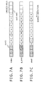
- FIGS. 7A, 7B, and 7C for comparison with FIGS. 4A, 4B, and 4C, in this case, bits are allocated to a subband signal having a next lowest MNR without the sort process being performed, whereby the number of sorts is reduced.
- FIG. 8 is a flowchart representing in detail the process of step SP45 in FIG. 1.
- the dynamic bit allocation unit 4 sets the combination stored at the position following the end as a sort object.
- the dynamic bit allocation unit 4 sets the variable m for identifying a comparison object to sort num - 1, and thereby sets an MNR combination recorded at a position immediately preceding the sort object as the comparison object.
- the dynamic bit allocation unit 4 increments the variable sort num by a value of one.
- step SP85 the dynamic bit allocation unit 4 determines whether the variable m is higher than a value no + 1. No comparison object exists after the comparison object is sequentially changed from the end side to the head side and the MNR combination at the head of the processing objects becomes the comparison object. Hence, in these cases, the dynamic bit allocation unit 4 obtains a negative result in step SP85, and proceeds from step SP85 to step SP86.
- the MNR of this combination is the MNR recalculated in step SP79.
- step SP86 when the recording position (order[]) of the combination of the sort object is set and the variable sort num is set such that the subband signal for which a positive result is obtained in previous step SP80 and to which bit allocation is thus completed is not included as a comparison object in the subsequent sort process, a processing load can be further reduced.
- step SP87 the dynamic bit allocation unit 4 increments the variable no by a value of one.
- the dynamic bit allocation unit 4 returns to step SP72 (FIG. 6).
- step SP85 the dynamic bit allocation unit 4 proceeds to step SP88.
- step SP88 the dynamic bit allocation unit 4 determines whether the MNR (p mnr[index]) of the sort object identified by the index index is lower than the MNR (p mnr[order[m]]) of the combination identified by the variable m.
- the dynamic bit allocation unit 4 decrements the variable m by a value of one to change the comparison object to a combination recorded at an immediately preceding position.
- the dynamic bit allocation unit 4 then returns to step SP85.
- a subband analyzing filter bank 2 divides a sequentially input audio signal S1 into a plurality of subband signals, and a linear quantizer 3 quantizes each subband signal.
- a bit compressing unit 11 bit-compresses a result of the quantization process, and then a bit stream forming unit 5 converts the bit-compressed result into a bit stream S2 and outputs the bit stream S2.
- a fast Fourier transform unit 8 subjects the audio signal S1 to a fast Fourier transform process.
- a psychoacoustic model unit 9 analyzes a result of the fast Fourier transform process, and detects the SMR (signal-to-mask ratio) of each subband signal.
- the dynamic bit allocation unit 4 determines the MNR (Mask to Noise Ratio) of each subband signal of the audio signal S1 from the signal-to-mask ratio SMR, and determines bit allocation and a quantization scale on the basis of the MNR.
- the linear quantizer 3 performs the quantization process with the bit allocation and the quantization scale.
- the bit allocation process in the dynamic bit allocation unit 4 is performed by repeating a process of detecting a subband signal with an MNR having a lowest value among the plurality of subband signals to which to allocate bits and a process of allocating bits to the detected subband signal and recalculating the MNR, and allocating all allocatable bits to each subband signal of each channel.
- the quantization scale of each subband signal is set so as to correspond to this bit allocation.
- the dynamic bit allocation unit 4 (FIG. 1) first sorts the MNRs of respective subbands in increasing order of MNR, and allocates bits to the subband signal having the MNR recorded at the head of a result of the sort (FIGS. 2A, 2B, and 2C).
- the MNR of the subband signal to which the bits are allocated is recalculated and re-sorted (FIGS. 3A, 3B, and 3C). Bits are allocated to the subband signal having the MNR recorded at the head of the re-sorted MNRs.
- the dynamic bit allocation unit 4 repeats a process of recalculating and re-sorting the MNR and a process of allocating bits to the subband signal having the MNR recorded at the head of the re-sorted MNRs, whereby all bits are allocated to each subband signal of each channel.
- the dynamic bit allocation unit 4 performs a sort in advance, and then detects a subband signal to which to allocate bits. Therefore, as compared with the existing example, the subband signal to which to allocate bits can be detected more quickly.
- the MNRs of the audio signal S1 are first calculated on the basis of an initial setting, and combinations of the calculated MNRs, indexes index, and statuses used are stored in the memory one by one and sorted (FIG. 5).
- an MNR combination is stored at an end of a row of MNR combinations already stored in the memory (step SP57 (FIG. 5)), and the order of arrangement is changed between the MNR combination and a combination stored at an immediately preceding position until an MNR having a lower value is detected (steps SP58, SP61, SP62, SP58, ..., SP58, SP61, and SP63 in this order, or steps SP58, SP61, SP62, SP58, ..., SP58, and SP59 in this order (FIG. 5)), whereby a sort is performed.
- an MNR combination stored at the head includes an MNR having a lowest value, and bits are allocated to the channel and the subband signal of the combination at the head (steps SP71 and SP74, SP75, and SP77 in this order (FIG. 6)).
- a corresponding MNR already stored in the memory is excluded from processing objects, and the recalculated MNR is stored at an end of a row of MNR combinations already stored in the memory (step SP84 (FIG. 8)).
- the order of arrangement is changed between the MNR combination and a combination stored at an immediately preceding position, and thereby a sort is performed (steps SP85, SP88, SP89, SP88, ..., SP85, SP88, and SP87 in this order, or steps SP85, SP88, SP89, SP88, ..., SP85, and SP90 in this order (FIG. 8)).
- an MNR combination stored at the head includes an MNR having a lowest value, and bits are allocated to the channel and the subband signal of the combination at the head (steps SP71 and SP74, SP75, and SP77 in this order (FIG. 6)).
- bit allocation to the subband signal of the combination at the head of the sort result it suffices to allocate bits to the subband signal of a next combination in the sort result (steps SP56, SP60, SP54, SP55, SP56, and SP57 in this order (FIG. 5)). It is therefore possible to reduce the number of sorts as the processing progresses, and simplify the process of detecting a minimum MNR for subband signals to which bits can be allocated.
- MNRs are sorted in advance and a minimum MNR is detected quickly
- the MNRs are sorted in the present embodiment, and it thus appears that a load of the processing viewed as a whole is not different from that of the existing example.
- the combination of the recalculated MNR is stored at an end of a sort result already stored in the memory, and thereafter the order of arrangement is changed between the combination of the recalculated MNR and a combination stored at an immediately preceding position until an MNR having a lower value is detected, whereby a sort is performed.
- the sort result so far is utilized effectively, and the MNRs are sorted by partly changing the sequence of the sort result so far.
- the load of the processing viewed as a whole can be reduced as compared with the existing example.
- an amount of processing of the encoder as a whole can be reduced by 52 [%] as compared with the processing performed by the existing example.
- MNRs are sorted in advance and a subband signal to which to allocate bits is detected.
- the combination of the recalculated MNR is stored at an end of a row of MNR combinations already stored in the memory, and thereafter the order of arrangement is changed between the combination of the recalculated MNR and a combination stored at an immediately preceding position until an MNR having a lower value is detected, whereby a sort is performed. It is thus possible to utilize the sort result so far effectively, and sort the MNRs by partly changing the sequence of the sort result so far. Hence, the load of processing can be reduced as compared with the existing example.
- FIG. 9 is a flowchart representing a processing procedure of a dynamic bit allocation unit 4 in an encoder according to a second embodiment of the present invention, for comparison with FIG. 1.
- the encoder according to the second embodiment is formed in the same manner as the encoder described above with reference to FIG. 16 except for the different processing procedure of the dynamic bit allocation unit 4 in the encoder according to the second embodiment. Therefore the following description will be made using the configuration of FIG. 16 as appropriate.
- the dynamic bit allocation unit 4 is formed in the same manner as in the encoder described above with reference to FIG. 1 except for a different re-sort process in step SP100.
- the same processes as those of the dynamic bit allocation unit 4 described in the first embodiment are identified by the same reference numerals, and repeated description thereof will be omitted.
- the dynamic bit allocation unit 4 proceeds from step SP99 to step SP42, where the dynamic bit allocation unit 4 sorts the MNR of each subband signal together with an index index and the like, and stores the MNR of each subband signal in a memory together with the index index and the like.
- the dynamic bit allocation unit 4 allocates bits to a subband signal with an MNR having a lowest value, and then recalculates the MNR of the subband signal to which the bits are allocated.
- the dynamic bit allocation unit 4 determines whether all allocatable bits are allocated. When a negative result is obtained in step SP44, the dynamic bit allocation unit 4 proceeds from step SP44 to step SP100.
- the dynamic bit allocation unit 4 applies the MNR recalculated in step SP44 to re-sort the MNRs recorded in the memory.
- the dynamic bit allocation unit 4 sorts the MNRs by partly changing the sequence of a sort result so far.
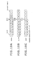
- the dynamic bit allocation unit 4 sequentially moves combinations of the sort result so far to a head side as indicated by arrows in the memory where the sort result is recorded until an MNR having a value higher than the recalculated MNR is detected.
- the dynamic bit allocation unit 4 records a combination including the recalculated MNR in a free space obtained by moving the combinations.
- the dynamic bit allocation unit 4 After completing the process of step SP100, the dynamic bit allocation unit 4 returns to step SP43, where the dynamic bit allocation unit 4 detects an MNR having a lowest value recorded at the head of processing objects from the sort result obtained by the sorting in step SP100.
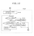
- FIG. 12 is a flowchart representing in detail the process of step SP100 in FIG. 9.
- the dynamic bit allocation unit 4 sets a variable m for identifying a comparison object to no + 1, and thereby sets an MNR combination recorded at a position immediately succeeding the sort object as the comparison object.
- step SP102 the dynamic bit allocation unit 4 determines whether the variable m is lower than a variable sort num. No comparison object exists after the comparison object is sequentially changed from a head side to an end side and a last MNR combination becomes the comparison object. Hence, in this case, the dynamic bit allocation unit 4 obtains a negative result in step SP102, and then proceeds from step SP102 to step SP103.
- step SP104 the dynamic bit allocation unit 4 determines whether the MNR (p mnr[index]) of the sort object identified by the index index is lower than the MNR (p mnr[order[m]]) of the combination identified by the variable m.
- the dynamic bit allocation unit 4 increments the variable m by a value of one to change the comparison object to a combination recorded at an immediately succeeding position.
- the dynamic bit allocation unit 4 then returns to step SP102.
- the present embodiment can provide similar effects to those of the first embodiment even when the re-sorting process is performed from a side of lower MNR values.
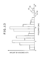
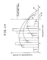
- the present embodiment detects the subband signals B3 and B4 that cause the degradation in sound quality, and reallocates the bits allocated to the subband signals B3 and B4 to other subband signals, as indicated by arrows.
- FIG. 15 is a flowchart of a processing procedure of a dynamic bit allocation unit 4 in an encoder according to a third embodiment of the present invention.
- the encoder according to the third embodiment is formed in the same manner as the encoder described above with reference to FIG. 16 except for the different processing procedure of the dynamic bit allocation unit 4 in the encoder according to the third embodiment. Therefore the following description will be made using the configuration of FIG. 16 as appropriate.
- the dynamic bit allocation unit 4 performs the processing procedure for each block of an audio signal S1. Starting this processing procedure, the dynamic bit allocation unit 4 proceeds from step SP121 to step SP122, where the dynamic bit allocation unit 4 calculates a bit allocation to each subband signal by performing the processing procedure of FIG. 1 or FIG. 9.
- step SP123 the dynamic bit allocation unit 4 determines whether there is a bit allocation to a subband signal causing degradation in sound quality.
- step SP123 the dynamic bit allocation unit 4 determines that there is a bit allocation to a subband signal causing degradation in sound quality when there is no bit allocation to a subband signal in a band on a lower frequency side of a band of frequencies equal to and higher than a certain frequency, there is a bit allocation to a subband signal in a band on a higher frequency side, and further the number of bits allocated to the subband signal in the band on the higher frequency side is equal to or smaller than a certain number.
- step SP123 When a negative result is obtained in step SP123, the dynamic bit allocation unit 4 proceeds from step SP123 to step SP124, where the dynamic bit allocation unit 4 ends the processing procedure.
- step SP123 When a positive result is obtained in step SP123, on the other hand, the dynamic bit allocation unit 4 proceeds from step SP123 to step SP125.
- step SP125 the dynamic bit allocation unit 4 calculates the number of bits allocated to the subband signal causing the degradation in sound quality.
- the dynamic bit allocation unit 4 calculates the number of bits allocated to the subband signals B3 and B4.
- step SP126 the dynamic bit allocation unit 4 allocates the amount of bits which amount is calculated in step SP125 to another subband signal.
- the dynamic bit allocation unit 4 performs the process of step SP126 by performing the processing procedure of FIG. 1 or FIG. 9 again. Specifically, the dynamic bit allocation unit 4 first sets the statuses used of the subband signals B3 and B4 causing degradation in sound quality and the subband signals B1 and B2 that are adjacent on the lower frequency side to the subband signals B3 and B4 and to which no bits are allocated to indicating completion of bit allocation, so that no bits are to be allocated to the subband signals B1 to B4.
- the dynamic bit allocation unit 4 sets the amount of bits that have previously been allocated to the subband signals B3 and B4 as an amount of remaining allocatable bits, repeats the processes of re-sorting (step SP45 or step SP100) and bit allocation (step SP43) described above with reference to FIG. 1 or FIG. 9, and thereby allocates the bits that have previously been allocated to the subband signals B3 and B4 to other subband signals.
- the process of step SP126 may be performed by restarting the process of FIG. 1 or FIG. 9 from the beginning.
- a setting may be simply made so that no bits are allocated to only the subband signals B3 and B4 that cause degradation in sound quality and to which bits have previously been allocated.
- the present embodiment detects a bit allocation to a subband signal causing degradation in sound quality, and reallocates bits allocated to the subband signal to another subband signal. It is thereby possible to prevent degradation in sound quality by a simple process.
- MNRs are sorted in order of increasing MNR value
- the present invention is not limited to this, and MNRs may conversely be sorted in order of decreasing MNR value.
- the process of detecting an MNR having a lowest value is performed in a manner opposite to that of the foregoing embodiment, that is, from an end of a sort result, and the processes of MNR re-sorting and the like are performed in an opposite direction to that of the foregoing embodiment.
- the encoder is formed by a digital signal processor
- the present invention is not limited to this, and is applicable to cases where an audio signal is subjected to an editing process by a computer, for example, and is thus widely applicable to cases where an audio signal is subjected to an encoding process by executing a program of arithmetic processing means, for example.
- the program of an audio signal encoding method which program is executed by such arithmetic processing means may be provided in a state of being recorded on various recording media such as optical disks, magnetic disks and memory cards, or may be provided via a network such as the Internet.
- the present invention is applicable to cases where audio signals are encoded by Layer 1 and Layer 2 of MPEG1 and MPEG2, for example.
Landscapes
- Engineering & Computer Science (AREA)
- Physics & Mathematics (AREA)
- Computational Linguistics (AREA)
- Signal Processing (AREA)
- Health & Medical Sciences (AREA)
- Audiology, Speech & Language Pathology (AREA)
- Human Computer Interaction (AREA)
- Acoustics & Sound (AREA)
- Multimedia (AREA)
- Spectroscopy & Molecular Physics (AREA)
- Theoretical Computer Science (AREA)
- Compression, Expansion, Code Conversion, And Decoders (AREA)
Applications Claiming Priority (1)
| Application Number | Priority Date | Filing Date | Title |
|---|---|---|---|
| JP2006086927A JP2007264154A (ja) | 2006-03-28 | 2006-03-28 | オーディオ信号符号化方法、オーディオ信号符号化方法のプログラム、オーディオ信号符号化方法のプログラムを記録した記録媒体及びオーディオ信号符号化装置 |
Publications (2)
| Publication Number | Publication Date |
|---|---|
| EP1840873A1 true EP1840873A1 (de) | 2007-10-03 |
| EP1840873B1 EP1840873B1 (de) | 2009-12-02 |
Family
ID=38031054
Family Applications (1)
| Application Number | Title | Priority Date | Filing Date |
|---|---|---|---|
| EP07006188A Not-in-force EP1840873B1 (de) | 2006-03-28 | 2007-03-26 | Audiosignalkodierverfahren, Programm des Audiosignalkodierverfahrens, Aufzeichnungsmedium, auf dem das Programm des Audiosignalkodierverfahrens aufgezeichnet ist, und Audiosignalkodiervorrichtung |
Country Status (7)
| Country | Link |
|---|---|
| US (1) | US20070244699A1 (de) |
| EP (1) | EP1840873B1 (de) |
| JP (1) | JP2007264154A (de) |
| KR (1) | KR20070097332A (de) |
| CN (1) | CN101046962B (de) |
| DE (1) | DE602007003497D1 (de) |
| TW (1) | TWI349926B (de) |
Cited By (2)
| Publication number | Priority date | Publication date | Assignee | Title |
|---|---|---|---|---|
| US9537694B2 (en) | 2012-03-29 | 2017-01-03 | Huawei Technologies Co., Ltd. | Signal coding and decoding methods and devices |
| CN108449704A (zh) * | 2013-10-22 | 2018-08-24 | 韩国电子通信研究院 | 生成用于音频信号的滤波器的方法及其参数化装置 |
Families Citing this family (10)
| Publication number | Priority date | Publication date | Assignee | Title |
|---|---|---|---|---|
| CN101605017A (zh) * | 2008-06-12 | 2009-12-16 | 华为技术有限公司 | 编码比特的分配方法和装置 |
| CN101853663B (zh) * | 2009-03-30 | 2012-05-23 | 华为技术有限公司 | 比特分配方法、编码装置及解码装置 |
| CN101645272B (zh) * | 2009-09-08 | 2012-01-25 | 华为终端有限公司 | 生成量化控制参数的方法、装置及音频编码设备 |
| CN105825858B (zh) | 2011-05-13 | 2020-02-14 | 三星电子株式会社 | 比特分配、音频编码和解码 |
| US8781023B2 (en) * | 2011-11-01 | 2014-07-15 | At&T Intellectual Property I, L.P. | Method and apparatus for improving transmission of data on a bandwidth expanded channel |
| US8774308B2 (en) * | 2011-11-01 | 2014-07-08 | At&T Intellectual Property I, L.P. | Method and apparatus for improving transmission of data on a bandwidth mismatched channel |
| CN103839551A (zh) * | 2012-11-22 | 2014-06-04 | 鸿富锦精密工业(深圳)有限公司 | 音频处理系统与音频处理方法 |
| CN105976824B (zh) | 2012-12-06 | 2021-06-08 | 华为技术有限公司 | 信号解码的方法和设备 |
| US9564136B2 (en) * | 2014-03-06 | 2017-02-07 | Dts, Inc. | Post-encoding bitrate reduction of multiple object audio |
| CN108520763B (zh) * | 2018-04-13 | 2021-07-16 | 广州醇美电子有限公司 | 一种数据存储方法、装置、设备和存储介质 |
Citations (6)
| Publication number | Priority date | Publication date | Assignee | Title |
|---|---|---|---|---|
| EP0661821A1 (de) | 1993-11-25 | 1995-07-05 | SHARP Corporation | Kodier- und Dekodierapparat welcher keine Tonqualität verschlechtert, sogar wenn ein Sinuswellen-Signal dekodiert wird |
| EP0665547A2 (de) | 1994-01-28 | 1995-08-02 | Samsung Electronics Co., Ltd. | System zum Kodieren und Dekodieren |
| JPH08123488A (ja) | 1994-10-24 | 1996-05-17 | Sony Corp | 高能率符号化方法、高能率符号記録方法、高能率符号伝送方法、高能率符号化装置及び高能率符号復号化方法 |
| EP0855805A2 (de) | 1997-01-22 | 1998-07-29 | Sharp Kabushiki Kaisha | Verfahren zum Kodieren von digitalen Audiosignalen |
| WO2002091363A1 (en) | 2001-05-08 | 2002-11-14 | Koninklijke Philips Electronics N.V. | Audio coding |
| US20040030548A1 (en) * | 2002-08-08 | 2004-02-12 | El-Maleh Khaled Helmi | Bandwidth-adaptive quantization |
Family Cites Families (9)
| Publication number | Priority date | Publication date | Assignee | Title |
|---|---|---|---|---|
| JPH10240297A (ja) * | 1996-12-27 | 1998-09-11 | Mitsubishi Electric Corp | 音響信号符号化装置 |
| JPH11219197A (ja) * | 1998-02-02 | 1999-08-10 | Fujitsu Ltd | オーディオ信号符号化方法及び装置 |
| JP3802219B2 (ja) * | 1998-02-18 | 2006-07-26 | 富士通株式会社 | 音声符号化装置 |
| JP2000293199A (ja) * | 1999-04-05 | 2000-10-20 | Nippon Columbia Co Ltd | 音声符号化方法および記録再生装置 |
| JP2000349643A (ja) * | 1999-06-08 | 2000-12-15 | Canon Inc | ディジタルオーディオ信号圧縮装置、ディジタルオーディオ信号圧縮方法及び記憶媒体 |
| JP2001242893A (ja) * | 2000-03-01 | 2001-09-07 | Matsushita Electric Ind Co Ltd | 帯域分割音声圧縮符号化方法および装置 |
| JP2002006895A (ja) * | 2000-06-20 | 2002-01-11 | Fujitsu Ltd | ビット割当装置および方法 |
| JP2002091500A (ja) * | 2000-09-19 | 2002-03-27 | Sharp Corp | デジタルデータ符号化方法 |
| US7996234B2 (en) * | 2003-08-26 | 2011-08-09 | Akikaze Technologies, Llc | Method and apparatus for adaptive variable bit rate audio encoding |
-
2006
- 2006-03-28 JP JP2006086927A patent/JP2007264154A/ja active Pending
-
2007
- 2007-03-21 TW TW096109782A patent/TWI349926B/zh not_active IP Right Cessation
- 2007-03-26 DE DE602007003497T patent/DE602007003497D1/de active Active
- 2007-03-26 KR KR1020070029412A patent/KR20070097332A/ko not_active Withdrawn
- 2007-03-26 US US11/728,717 patent/US20070244699A1/en not_active Abandoned
- 2007-03-26 EP EP07006188A patent/EP1840873B1/de not_active Not-in-force
- 2007-03-28 CN CN2007100888200A patent/CN101046962B/zh not_active Expired - Fee Related
Patent Citations (6)
| Publication number | Priority date | Publication date | Assignee | Title |
|---|---|---|---|---|
| EP0661821A1 (de) | 1993-11-25 | 1995-07-05 | SHARP Corporation | Kodier- und Dekodierapparat welcher keine Tonqualität verschlechtert, sogar wenn ein Sinuswellen-Signal dekodiert wird |
| EP0665547A2 (de) | 1994-01-28 | 1995-08-02 | Samsung Electronics Co., Ltd. | System zum Kodieren und Dekodieren |
| JPH08123488A (ja) | 1994-10-24 | 1996-05-17 | Sony Corp | 高能率符号化方法、高能率符号記録方法、高能率符号伝送方法、高能率符号化装置及び高能率符号復号化方法 |
| EP0855805A2 (de) | 1997-01-22 | 1998-07-29 | Sharp Kabushiki Kaisha | Verfahren zum Kodieren von digitalen Audiosignalen |
| WO2002091363A1 (en) | 2001-05-08 | 2002-11-14 | Koninklijke Philips Electronics N.V. | Audio coding |
| US20040030548A1 (en) * | 2002-08-08 | 2004-02-12 | El-Maleh Khaled Helmi | Bandwidth-adaptive quantization |
Non-Patent Citations (1)
| Title |
|---|
| ASHIDA S ET AL: "Sampled-data audio signal compression with huffman coding", SICE 2004 ANNUAL CONFERENCE SAPPORO, JAPAN AUG. 4-6, 2004, PISCATAWAY, NJ, USA,IEEE, 4 August 2004 (2004-08-04), pages 972 - 976, XP010824665, ISBN: 4-907764-22-7 * |
Cited By (4)
| Publication number | Priority date | Publication date | Assignee | Title |
|---|---|---|---|---|
| US9537694B2 (en) | 2012-03-29 | 2017-01-03 | Huawei Technologies Co., Ltd. | Signal coding and decoding methods and devices |
| US9786293B2 (en) | 2012-03-29 | 2017-10-10 | Huawei Technologies Co., Ltd. | Signal coding and decoding methods and devices |
| US9899033B2 (en) | 2012-03-29 | 2018-02-20 | Huawei Technologies Co., Ltd. | Signal coding and decoding methods and devices |
| CN108449704A (zh) * | 2013-10-22 | 2018-08-24 | 韩国电子通信研究院 | 生成用于音频信号的滤波器的方法及其参数化装置 |
Also Published As
| Publication number | Publication date |
|---|---|
| EP1840873B1 (de) | 2009-12-02 |
| DE602007003497D1 (de) | 2010-01-14 |
| US20070244699A1 (en) | 2007-10-18 |
| TWI349926B (en) | 2011-10-01 |
| KR20070097332A (ko) | 2007-10-04 |
| CN101046962B (zh) | 2011-02-09 |
| JP2007264154A (ja) | 2007-10-11 |
| CN101046962A (zh) | 2007-10-03 |
| TW200818121A (en) | 2008-04-16 |
Similar Documents
| Publication | Publication Date | Title |
|---|---|---|
| EP1840873B1 (de) | Audiosignalkodierverfahren, Programm des Audiosignalkodierverfahrens, Aufzeichnungsmedium, auf dem das Programm des Audiosignalkodierverfahrens aufgezeichnet ist, und Audiosignalkodiervorrichtung | |
| CN1095253C (zh) | 宽带数字信息信号的编码和解码设备和方法 | |
| RU2636697C1 (ru) | Устройство и способ кодирования | |
| US20060004566A1 (en) | Low-bitrate encoding/decoding method and system | |
| EP1403854A2 (de) | Kodierung und Dekodierung von mehrkanaligen Tonsignalen | |
| US8149927B2 (en) | Method of and apparatus for encoding/decoding digital signal using linear quantization by sections | |
| US5588024A (en) | Frequency subband encoding apparatus | |
| CN100489965C (zh) | 音频编码系统 | |
| JP2004199064A (ja) | ビット率を調節できるオーディオ符号化方法、復号方法、符号化装置及び復号装置 | |
| US5761636A (en) | Bit allocation method for improved audio quality perception using psychoacoustic parameters | |
| US8086465B2 (en) | Transform domain transcoding and decoding of audio data using integer-reversible modulated lapped transforms | |
| CN1222993A (zh) | 可变位速率语音传输系统 | |
| EP2203917B1 (de) | Schnelle spektrale partitionierung zur effizienten codierung | |
| CN1111960C (zh) | 数字数据编码装置及其方法 | |
| BRPI0506627B1 (pt) | método e dispositivo para quantizar um sinal de informações | |
| US7933416B2 (en) | Method and apparatus for encoding and decoding multi-channel signals | |
| JP2993324B2 (ja) | 音声高能率符号化装置 | |
| JP2842275B2 (ja) | 信号蓄積方法および信号再生方法 | |
| JP2008139781A (ja) | 音声符号化方法および装置 | |
| JP2001242893A (ja) | 帯域分割音声圧縮符号化方法および装置 | |
| JP2001325000A (ja) | オーディオ信号符号化装置 |
Legal Events
| Date | Code | Title | Description |
|---|---|---|---|
| PUAI | Public reference made under article 153(3) epc to a published international application that has entered the european phase |
Free format text: ORIGINAL CODE: 0009012 |
|
| AK | Designated contracting states |
Kind code of ref document: A1 Designated state(s): AT BE BG CH CY CZ DE DK EE ES FI FR GB GR HU IE IS IT LI LT LU LV MC MT NL PL PT RO SE SI SK TR |
|
| AX | Request for extension of the european patent |
Extension state: AL BA HR MK YU |
|
| 17P | Request for examination filed |
Effective date: 20071221 |
|
| AKX | Designation fees paid |
Designated state(s): DE FR GB |
|
| GRAP | Despatch of communication of intention to grant a patent |
Free format text: ORIGINAL CODE: EPIDOSNIGR1 |
|
| GRAS | Grant fee paid |
Free format text: ORIGINAL CODE: EPIDOSNIGR3 |
|
| GRAA | (expected) grant |
Free format text: ORIGINAL CODE: 0009210 |
|
| AK | Designated contracting states |
Kind code of ref document: B1 Designated state(s): DE FR GB |
|
| REG | Reference to a national code |
Ref country code: GB Ref legal event code: FG4D |
|
| REF | Corresponds to: |
Ref document number: 602007003497 Country of ref document: DE Date of ref document: 20100114 Kind code of ref document: P |
|
| PLBE | No opposition filed within time limit |
Free format text: ORIGINAL CODE: 0009261 |
|
| STAA | Information on the status of an ep patent application or granted ep patent |
Free format text: STATUS: NO OPPOSITION FILED WITHIN TIME LIMIT |
|
| 26N | No opposition filed |
Effective date: 20100903 |
|
| PGFP | Annual fee paid to national office [announced via postgrant information from national office to epo] |
Ref country code: FR Payment date: 20110404 Year of fee payment: 5 |
|
| PGFP | Annual fee paid to national office [announced via postgrant information from national office to epo] |
Ref country code: DE Payment date: 20110325 Year of fee payment: 5 Ref country code: GB Payment date: 20110321 Year of fee payment: 5 |
|
| GBPC | Gb: european patent ceased through non-payment of renewal fee |
Effective date: 20120326 |
|
| REG | Reference to a national code |
Ref country code: FR Ref legal event code: ST Effective date: 20121130 |
|
| PG25 | Lapsed in a contracting state [announced via postgrant information from national office to epo] |
Ref country code: FR Free format text: LAPSE BECAUSE OF NON-PAYMENT OF DUE FEES Effective date: 20120402 Ref country code: GB Free format text: LAPSE BECAUSE OF NON-PAYMENT OF DUE FEES Effective date: 20120326 |
|
| REG | Reference to a national code |
Ref country code: DE Ref legal event code: R119 Ref document number: 602007003497 Country of ref document: DE Effective date: 20121002 |
|
| PG25 | Lapsed in a contracting state [announced via postgrant information from national office to epo] |
Ref country code: DE Free format text: LAPSE BECAUSE OF NON-PAYMENT OF DUE FEES Effective date: 20121002 |