EP1841302A2 - Appareil de commande électronique dans des véhicules - Google Patents
Appareil de commande électronique dans des véhicules Download PDFInfo
- Publication number
- EP1841302A2 EP1841302A2 EP07011788A EP07011788A EP1841302A2 EP 1841302 A2 EP1841302 A2 EP 1841302A2 EP 07011788 A EP07011788 A EP 07011788A EP 07011788 A EP07011788 A EP 07011788A EP 1841302 A2 EP1841302 A2 EP 1841302A2
- Authority
- EP
- European Patent Office
- Prior art keywords
- housing
- control unit
- electronic control
- unit according
- rail
- Prior art date
- Legal status (The legal status is an assumption and is not a legal conclusion. Google has not performed a legal analysis and makes no representation as to the accuracy of the status listed.)
- Granted
Links
- 238000001816 cooling Methods 0.000 claims description 9
- 239000004065 semiconductor Substances 0.000 claims description 8
- 230000000295 complement effect Effects 0.000 claims description 3
- 238000001125 extrusion Methods 0.000 claims description 3
- 239000003990 capacitor Substances 0.000 description 5
- XAGFODPZIPBFFR-UHFFFAOYSA-N aluminium Chemical compound [Al] XAGFODPZIPBFFR-UHFFFAOYSA-N 0.000 description 1
- 229910052782 aluminium Inorganic materials 0.000 description 1
- 230000037431 insertion Effects 0.000 description 1
- 238000003780 insertion Methods 0.000 description 1
- 238000009434 installation Methods 0.000 description 1
- 230000003993 interaction Effects 0.000 description 1
- 239000000463 material Substances 0.000 description 1
- 238000007789 sealing Methods 0.000 description 1
Images


Classifications
-
- B—PERFORMING OPERATIONS; TRANSPORTING
- B60—VEHICLES IN GENERAL
- B60R—VEHICLES, VEHICLE FITTINGS, OR VEHICLE PARTS, NOT OTHERWISE PROVIDED FOR
- B60R16/00—Electric or fluid circuits specially adapted for vehicles and not otherwise provided for; Arrangement of elements of electric or fluid circuits specially adapted for vehicles and not otherwise provided for
- B60R16/02—Electric or fluid circuits specially adapted for vehicles and not otherwise provided for; Arrangement of elements of electric or fluid circuits specially adapted for vehicles and not otherwise provided for electric constitutive elements
- B60R16/023—Electric or fluid circuits specially adapted for vehicles and not otherwise provided for; Arrangement of elements of electric or fluid circuits specially adapted for vehicles and not otherwise provided for electric constitutive elements for transmission of signals between vehicle parts or subsystems
- B60R16/0239—Electronic boxes
-
- H—ELECTRICITY
- H05—ELECTRIC TECHNIQUES NOT OTHERWISE PROVIDED FOR
- H05K—PRINTED CIRCUITS; CASINGS OR CONSTRUCTIONAL DETAILS OF ELECTRIC APPARATUS; MANUFACTURE OF ASSEMBLAGES OF ELECTRICAL COMPONENTS
- H05K5/00—Casings, cabinets or drawers for electric apparatus
- H05K5/0026—Casings, cabinets or drawers for electric apparatus provided with connectors and printed circuit boards [PCB], e.g. automotive electronic control units
- H05K5/0039—Casings, cabinets or drawers for electric apparatus provided with connectors and printed circuit boards [PCB], e.g. automotive electronic control units having a tubular housing wherein the PCB is inserted longitudinally
-
- H—ELECTRICITY
- H05—ELECTRIC TECHNIQUES NOT OTHERWISE PROVIDED FOR
- H05K—PRINTED CIRCUITS; CASINGS OR CONSTRUCTIONAL DETAILS OF ELECTRIC APPARATUS; MANUFACTURE OF ASSEMBLAGES OF ELECTRICAL COMPONENTS
- H05K7/00—Constructional details common to different types of electric apparatus
- H05K7/14—Mounting supporting structure in casing or on frame or rack
- H05K7/1417—Mounting supporting structure in casing or on frame or rack having securing means for mounting boards, plates or wiring boards
- H05K7/142—Spacers not being card guides
-
- H—ELECTRICITY
- H05—ELECTRIC TECHNIQUES NOT OTHERWISE PROVIDED FOR
- H05K—PRINTED CIRCUITS; CASINGS OR CONSTRUCTIONAL DETAILS OF ELECTRIC APPARATUS; MANUFACTURE OF ASSEMBLAGES OF ELECTRICAL COMPONENTS
- H05K7/00—Constructional details common to different types of electric apparatus
- H05K7/20—Modifications to facilitate cooling, ventilating, or heating
- H05K7/20845—Modifications to facilitate cooling, ventilating, or heating for automotive electronic casings
- H05K7/20854—Heat transfer by conduction from internal heat source to heat radiating structure
Definitions
- the invention relates to an electronic control unit in vehicles, which has a metallic housing for receiving electronic components.
- the electronic components accommodated in the metallic housing of such an electronic control unit are used, for example, for controlling occupant restraint systems connected to the control unit, such as belt tensioners and airbags.
- the electronic components are firmly connected to the housing body.
- Previous housing of such controllers have on their side walls guide grooves on which a circuit board can be inserted into the housing.
- the circuit board is additionally supported in the inserted state by formed on the back of the housing guide elements. Due to the lateral and rear attachment of the guide elements, it is necessary that the circuit board occupies the entire length and width of the housing.
- the invention provides a control device whose electronic components are reliably and firmly connected to the housing body and whose housing body can be used to accommodate electronic components of different sizes.
- at least one rail-shaped guide element is on the inside of the housing educated.
- At least one fastening element for an electronic component can be brought into positive engagement with the rail-shaped fastening element. Due to the interaction of the rail-shaped guide element with the fastening element, the electronic component is securely and firmly connected to the housing. It can therefore be dispensed with a rear guide element, so that for example the same housing can be used regardless of the size of the circuit board and the electronic modules arranged thereon.
- the rail-shaped guide element forms an internally enlarged channel into which the fastening element can be inserted.
- the insertion offers the advantage of a simple and fast and thus inexpensive mounting of the electronic components.
- a housing is provided, on the outside of which cooling ribs are formed.
- a arranged on a printed circuit power semiconductor is thermally conductively connected via the fastening element with the housing.
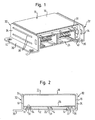
- the control device shown in Figures 1 and 2 comprises a housing 10 with a housing body 11, on the bottom wall 12 on the inside three parallel, over the entire length of the bottom wall 12 extending rail-shaped guide elements 14 are formed.
- the housing body 11 also has a cover wall 16 and two side walls 18.
- the housing body 11 is preferably made in one piece by extrusion from aluminum.
- the rail-shaped guide elements 14 each form a channel 22 widened on the inside.
- a metallic fastening element 24 is inserted with its lower end with respect to FIG.
- the fastening element 24 is formed at its lower end with respect to Figure 2 so that it is positively engaged with the inside enlarged channel 22 of the rail-shaped guide member 14.
- the fastening element 24 is fastened to a printed circuit board 26.
- the fastener 24 may be, for example, a pin or pin that is pressed against an opening formed in the printed circuit board 26.
- the fastener 24 is first attached to the printed circuit board 26 with its upper end with respect to FIG. Subsequently, the circuit board 26, at one end of a plug socket 28 is mounted (see also Figure 1), inserted into the housing body 11, in such a way that with respect to Figure 2 lower end of the fastener 24 in engagement with the inside extended channel 22 of the rail-shaped guide member 14 is brought and is moved along this channel. Since the fastening element 24 and the channel 22 engage in a form-fitting manner, the printed circuit board is only displaceable along the guide rails, but not in the two directions perpendicular thereto. The printed circuit board 26 is completely inserted and positioned in the housing when the plug socket 28 is latched at a front end 30 of the housing body 11.
- the housing body 11 In order to completely block the fastening element 24 with the printed circuit board 26 in the channel 22, the housing body 11 is locally deformed from its outside in the region 31 of the bottom wall 12, which is located below the fastening element 24. As a result, an electrically conductive connection between the printed circuit board 26 and the housing body 11 is also produced via the fastening element 24 at the same time.
- the circuit board is securely and firmly connected to the housing body. Since the fastener can be attached anywhere on the circuit board, the same housing can serve to accommodate printed circuit boards of different sizes.
- a mounting bracket 32 with a first angle leg 34 and a second angle leg 36 perpendicular thereto is provided on the side walls 18 of the housing body 11.
- two rib-shaped projections 38 are integrally formed on a side wall 18 of the housing body 11 according to the embodiment shown in Figures 1 and 2. These rib-shaped projections 38 are each used in and on the first angle leg 34 of the mounting bracket 32 formed and complementary to the rib-shaped projections slots and pressed.
- the second angle leg 36 of the mounting bracket 32 are each provided with openings 40 through which the housing 10 attached to the vehicle body, for example, can be screwed.
- the mounting brackets can be arranged relative to the housing 10 in such a way that the second angle leg 36, in which the openings 40 are formed, runs parallel to the bottom or top wall of the housing and with respect to the housing 10 protrudes outwards.
- the mounting bracket can also like the right angle with respect to Figure 1 mounting bracket 32 are arranged so that the second angle leg 36 is at least partially below the bottom wall of the housing body 11. The opening or the openings 40 are then in the region of the angle leg 36, which is not below the bottom wall 12 of the housing 10, but projects laterally.
- the attachment of the housing 10 to the vehicle body on the mounting bracket 32 has the advantage that the same housing can be installed in locations with differently shaped attachment points by depending on the installation mounting bracket with differently shaped openings 40 attached to the side walls of the housing body 11. Furthermore, the arrangement of the mounting angle and the length of the control unit can be varied, as will now be explained with reference to Figures 3a and 3b:
- a housing body 11 is shown with two mounting brackets 32, each having a greater length than the side wall 18 of the housing body 11 to which they are attached, so that they both protrude laterally with one of its ends 41.
- the plug collar 28 is located on the side opposite the two laterally projecting ends 41 side wall of the housing body 11, and it extends over almost the entire width of the side wall 18 of the housing body 11.
- the mounting bracket 32 are on the side wall 18th the housing body 11 addition, at which the plug collar 28 is located. As a result, the plug collar 28 can not extend over substantially the entire width of the side wall, as in the case of the control unit shown in FIG.
- the plug collar 28 has a seal 42 which in the mounted state rests against the outside of the housing body 11 (see also FIG. 4).
- the inside area of the plug collar 28 is formed with receiving elements 46 for accommodating capacitors 48.
- the capacitors 48 are at their plug collar 28 opposite end with a circuit board 50th electrically contacted.
- the attachment of the capacitors 48 in the receiving elements 46 in the inside region of the plug collar allows easy mounting of the capacitors. Furthermore, this space is saved, so that smaller dimensions of the housing body 11 are possible.
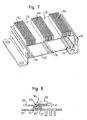
- the control unit shown in FIG. 7 differs from the control apparatus shown in FIGS. 1 and 6 in that cooling fins 150 are formed on the outside of the cover wall 116 of the housing body 111.
- the cooling fins 150 like the rail-shaped guide elements 114 together with the side walls 118, the top wall 116 and the bottom wall 112, can be manufactured in one piece by extrusion.
- This housing is preferably suitable for accommodating power electronic components, since the generated power loss can be dissipated by the large cooling surface of the housing body.
- a mounting option according to the invention of a printed circuit board 126 with a power semiconductor 160 arranged in it on the housing body 111 is shown in FIG.
- a fastening element 124 is connected analogously to the embodiment shown in Figure 2 at its one end to a printed circuit board 126 and at its other end in a form-fitting engagement with the internally enlarged channel 122 of a rail-shaped guide member 114.
- the bottom wall 112 of the housing body 111 is on the outside of the Housing body 111 is locally pressed in the region of the fastener 124 to block the fastener 124 in the channel 122.
- the fastening element 124 is provided with an internal thread.
- the power semiconductor 160 has a cooling lug 162, at which the power semiconductor is connected to the fastening element via a screw 164 introduced into the internal thread of the fastening element 124.
- the ones from Power semiconductors generated heat can be delivered via the screw 164 and the fastener 124 to the housing body 111 and from there to the environment.
Landscapes
- Engineering & Computer Science (AREA)
- Microelectronics & Electronic Packaging (AREA)
- Physics & Mathematics (AREA)
- Thermal Sciences (AREA)
- Mechanical Engineering (AREA)
- Cooling Or The Like Of Electrical Apparatus (AREA)
- Casings For Electric Apparatus (AREA)
- Mounting Components In General For Electric Apparatus (AREA)
- Mounting Of Printed Circuit Boards And The Like (AREA)
Applications Claiming Priority (2)
| Application Number | Priority Date | Filing Date | Title |
|---|---|---|---|
| DE20112594U DE20112594U1 (de) | 2001-07-31 | 2001-07-31 | Elektronisches Steuergerät in Fahrzeugen |
| EP02016343A EP1282344B8 (fr) | 2001-07-31 | 2002-07-25 | Appareil de contrôle électronique dans un véhicule |
Related Parent Applications (2)
| Application Number | Title | Priority Date | Filing Date |
|---|---|---|---|
| EP02016343.2 Division | 2002-07-25 | ||
| EP02016343A Division EP1282344B8 (fr) | 2001-07-31 | 2002-07-25 | Appareil de contrôle électronique dans un véhicule |
Publications (3)
| Publication Number | Publication Date |
|---|---|
| EP1841302A2 true EP1841302A2 (fr) | 2007-10-03 |
| EP1841302A3 EP1841302A3 (fr) | 2008-04-23 |
| EP1841302B1 EP1841302B1 (fr) | 2011-06-15 |
Family
ID=7959923
Family Applications (2)
| Application Number | Title | Priority Date | Filing Date |
|---|---|---|---|
| EP07011788A Expired - Lifetime EP1841302B1 (fr) | 2001-07-31 | 2002-07-25 | Appareil de commande électronique dans des véhicules |
| EP02016343A Expired - Lifetime EP1282344B8 (fr) | 2001-07-31 | 2002-07-25 | Appareil de contrôle électronique dans un véhicule |
Family Applications After (1)
| Application Number | Title | Priority Date | Filing Date |
|---|---|---|---|
| EP02016343A Expired - Lifetime EP1282344B8 (fr) | 2001-07-31 | 2002-07-25 | Appareil de contrôle électronique dans un véhicule |
Country Status (4)
| Country | Link |
|---|---|
| US (1) | US6788539B2 (fr) |
| EP (2) | EP1841302B1 (fr) |
| JP (1) | JP3837096B2 (fr) |
| DE (2) | DE20112594U1 (fr) |
Cited By (1)
| Publication number | Priority date | Publication date | Assignee | Title |
|---|---|---|---|---|
| FR2926399A1 (fr) * | 2008-01-16 | 2009-07-17 | Intelligent Electronic Systems | Boitier en profiles extrudes metalliques multi-positions pour la fabrication d'un dispositif electronique de puissance etanche |
Families Citing this family (24)
| Publication number | Priority date | Publication date | Assignee | Title |
|---|---|---|---|---|
| US6813161B2 (en) | 2002-05-09 | 2004-11-02 | Gateway, Inc. | Movable standoff for mounting a circuit board |
| US6778389B1 (en) * | 2003-07-03 | 2004-08-17 | Visteon Global Technologies, Inc. | Microelectronic package with tubular housing |
| US6968889B2 (en) * | 2003-11-21 | 2005-11-29 | Waffer Technology Corp. | Fastening structure of heat sink |
| DE102004005330A1 (de) | 2004-02-04 | 2005-08-25 | Conti Temic Microelectronic Gmbh | Metallisches Gehäuse |
| US7120024B2 (en) * | 2004-02-27 | 2006-10-10 | Fujitsu Ten Limited | Electronic control device |
| JP4526016B2 (ja) * | 2004-03-30 | 2010-08-18 | 本田技研工業株式会社 | 制御ボックス取付ブラケット |
| US7190589B2 (en) * | 2004-10-19 | 2007-03-13 | Cinch Connectors, Inc. | Electronic control enclosure |
| DE102005043135A1 (de) * | 2005-09-12 | 2007-03-22 | Hirschmann Electronics Gmbh | Antennendose mit mittels eines Radialtaumelnietvorganges festgelegter Leiterplatte |
| AT502498B1 (de) | 2005-10-11 | 2007-04-15 | Fronius Int Gmbh | Vorrichtung zur montage einer printplatte und zur wärmeableitung |
| US20080037222A1 (en) * | 2006-02-17 | 2008-02-14 | Ddcip Technologies, Inc. | Heat dissipation assembly |
| JP4317210B2 (ja) * | 2006-12-07 | 2009-08-19 | 東芝テック株式会社 | 表示装置 |
| CN101056506B (zh) * | 2007-06-15 | 2010-06-09 | 北京安控科技股份有限公司 | 一种封装电路板的外壳 |
| KR101079988B1 (ko) | 2009-12-14 | 2011-11-04 | 주식회사 신창전기 | 차량용 전자제어유닛 케이스 |
| JP5605137B2 (ja) * | 2010-09-30 | 2014-10-15 | トヨタ自動車株式会社 | 車両の部品取付構造体 |
| JP2013070028A (ja) * | 2011-09-07 | 2013-04-18 | Hitachi Automotive Systems Ltd | 電子制御装置 |
| US9293870B1 (en) * | 2015-03-10 | 2016-03-22 | Continental Automotive Systems, Inc. | Electronic control module having a cover allowing for inspection of right angle press-fit pins |
| US10368465B2 (en) * | 2017-09-07 | 2019-07-30 | Lear Corporation | Electrical unit |
| CN110572975B (zh) * | 2018-06-05 | 2020-12-15 | 台达电子工业股份有限公司 | 具有定位内部电路基板功能的电源供应器及其制作方法 |
| US11871532B2 (en) * | 2018-10-31 | 2024-01-09 | Hirschmann Automation And Control Gmbh | Housing for railroad switch |
| CN109275326A (zh) * | 2018-11-29 | 2019-01-25 | 徐州华琅自动化设备有限公司 | 一种电动车控制器用散热装置 |
| JP7205662B2 (ja) * | 2020-03-18 | 2023-01-17 | 富士電機株式会社 | 半導体モジュール |
| JP7632390B2 (ja) * | 2022-05-30 | 2025-02-19 | トヨタ自動車株式会社 | 車両 |
| DE102022208808A1 (de) * | 2022-08-25 | 2024-03-07 | Robert Bosch Gesellschaft mit beschränkter Haftung | Vorrichtung zur Kühlung einer zu kühlenden Einheit insbesondere eines Kraftfahrzeugs |
| US12513844B1 (en) * | 2024-10-01 | 2025-12-30 | Nokia Solutions And Networks Oy | Bracket assembly for mounting electronics units in racks |
Citations (2)
| Publication number | Priority date | Publication date | Assignee | Title |
|---|---|---|---|---|
| EP1006766A2 (fr) | 1998-12-01 | 2000-06-07 | Mannesmann VDO Aktiengesellschaft | Dispositif électronique |
| US6243270B1 (en) | 1996-11-14 | 2001-06-05 | Intel Corporation | Method and apparatus for attaching a printed circuit board to a chassis |
Family Cites Families (20)
| Publication number | Priority date | Publication date | Assignee | Title |
|---|---|---|---|---|
| DE1847846U (de) | 1961-08-03 | 1962-03-08 | Bbc Brown Boveri & Cie | Zweiteiliges gehaeuse. |
| US4853828A (en) * | 1985-08-22 | 1989-08-01 | Dart Controls, Inc. | Solid state device package mounting apparatus |
| US5019948A (en) * | 1989-11-10 | 1991-05-28 | Hewlett-Packard Company | T-rail printed circuit board guide and support |
| DE4242944C2 (de) | 1992-12-18 | 2002-04-25 | Bosch Gmbh Robert | Elektrisches Steuergerät |
| US5590026A (en) * | 1995-07-31 | 1996-12-31 | Borg-Warner Automotive, Inc. | Apparatus for dissipating heat from an integrated circuit |
| US5661640A (en) * | 1996-01-05 | 1997-08-26 | Dell Usa, L.P. | Computer chassis having a size-adjustable, TEM-shielded circuit board support plate structure therein |
| US5599080A (en) * | 1996-02-08 | 1997-02-04 | Ho; Hsin C. | Sliding case mounting device |
| US5742478A (en) * | 1996-09-25 | 1998-04-21 | Wu; Chih-Hsien | Radiating structure of a power converter |
| US5838538A (en) * | 1996-11-14 | 1998-11-17 | Intel Corporation | Computer system with a chassis equipped with support structures configured to support multiple length versions of a printed circuit board |
| DE19700558C1 (de) | 1997-01-10 | 1998-06-25 | Fischer Elektronik Gmbh & Co K | Gehäuse für elektronische Bauteile |
| DE19709243C1 (de) | 1997-03-06 | 1998-06-10 | Siemens Ag | Steuergerät für ein Kraftfahrzeug |
| JP3675607B2 (ja) * | 1997-05-12 | 2005-07-27 | アルプス電気株式会社 | 電子機器の放熱構造 |
| DE29801997U1 (de) | 1998-02-06 | 1998-07-02 | apra-gerätebau Dipl.-Ing. (FH) Wolfgang Appenzeller und Wilfried Rademacher GmbH & Co. KG, 54550 Daun | Variable Kartenführungseinrichtung für Elektronikgehäuse |
| DE19841258C1 (de) * | 1998-09-09 | 2000-03-16 | Siemens Ag | Steuergerät |
| DE19911990A1 (de) | 1999-03-17 | 2000-09-28 | Trw Automotive Electron & Comp | Metallgehäuse, insbesondere für ein Airbag-Steuergerät |
| DE19924344C2 (de) | 1999-05-27 | 2002-10-31 | Siemens Ag | Gehäuse für ein elektrisches oder elektronisches Gerät zum Einbau in ein Kraftfahrzeug |
| JP2001159931A (ja) * | 1999-09-24 | 2001-06-12 | Cybernetics Technology Co Ltd | コンピュータ |
| DE20004263U1 (de) | 2000-03-07 | 2001-01-04 | bopla Gehäuse Systeme GmbH, 32257 Bünde | Gehäuse mit einer Deckelplatte |
| US6377445B1 (en) * | 2000-08-14 | 2002-04-23 | Gateway, Inc. | Motherboard mounting assembly |
| US6493233B1 (en) * | 2001-08-21 | 2002-12-10 | Intel Corporation | PCB-to-chassis mounting schemes |
-
2001
- 2001-07-31 DE DE20112594U patent/DE20112594U1/de not_active Expired - Lifetime
-
2002
- 2002-07-25 EP EP07011788A patent/EP1841302B1/fr not_active Expired - Lifetime
- 2002-07-25 EP EP02016343A patent/EP1282344B8/fr not_active Expired - Lifetime
- 2002-07-25 DE DE50213211T patent/DE50213211D1/de not_active Expired - Lifetime
- 2002-07-29 US US10/207,353 patent/US6788539B2/en not_active Expired - Lifetime
- 2002-07-31 JP JP2002222393A patent/JP3837096B2/ja not_active Expired - Fee Related
Patent Citations (2)
| Publication number | Priority date | Publication date | Assignee | Title |
|---|---|---|---|---|
| US6243270B1 (en) | 1996-11-14 | 2001-06-05 | Intel Corporation | Method and apparatus for attaching a printed circuit board to a chassis |
| EP1006766A2 (fr) | 1998-12-01 | 2000-06-07 | Mannesmann VDO Aktiengesellschaft | Dispositif électronique |
Cited By (3)
| Publication number | Priority date | Publication date | Assignee | Title |
|---|---|---|---|---|
| FR2926399A1 (fr) * | 2008-01-16 | 2009-07-17 | Intelligent Electronic Systems | Boitier en profiles extrudes metalliques multi-positions pour la fabrication d'un dispositif electronique de puissance etanche |
| EP2081422A1 (fr) * | 2008-01-16 | 2009-07-22 | Intelligent Electronic Systems (IES) | Boîtier en profilés extrudés métalliques multi-positions pour la fabrication d'un dispositif électronique de puissance étanche |
| US8035964B2 (en) | 2008-01-16 | 2011-10-11 | Intelligent Electronic Systems | Multi-position housing made of metal extruded section member for manufacturing a waterproof power electronic device |
Also Published As
| Publication number | Publication date |
|---|---|
| EP1282344A2 (fr) | 2003-02-05 |
| DE50213211D1 (de) | 2009-03-05 |
| US20030048611A1 (en) | 2003-03-13 |
| EP1282344B1 (fr) | 2009-01-14 |
| JP2003179370A (ja) | 2003-06-27 |
| EP1841302A3 (fr) | 2008-04-23 |
| EP1282344B8 (fr) | 2009-04-01 |
| EP1282344A3 (fr) | 2005-11-02 |
| EP1841302B1 (fr) | 2011-06-15 |
| US6788539B2 (en) | 2004-09-07 |
| DE20112594U1 (de) | 2002-01-17 |
| JP3837096B2 (ja) | 2006-10-25 |
Similar Documents
| Publication | Publication Date | Title |
|---|---|---|
| EP1282344B1 (fr) | Appareil de contrôle électronique dans un véhicule | |
| DE10392749B4 (de) | Kontrollmodulgehäuse für ein Fahrzeug | |
| DE19919598C2 (de) | Mechanische und Elektrische Verbindungsvorrichtung für einen Anschlussblock | |
| EP2010500B1 (fr) | Dispositif de contact de semi-conducteurs de puissance sur une surface réfrigérante | |
| DE60116411T2 (de) | Baueinheit für den Cockpitbereich eines Personenkraftwagens und Verfahren zur Befestigung | |
| DE10304278B4 (de) | Struktur zur Befestigung einer Anzeigeeinheit an einer Instrumentenkonsole eines Automobils | |
| DE19722602A1 (de) | Wärmeableitendes Gehäuse zur Aufnahme von elektrischen oder elektronischen Bauteilen | |
| DE112014001321T5 (de) | Elektronikkomponenten-Anordnungsaufbau und elektrischer Anschlusskasten | |
| EP0526466B1 (fr) | Dispositif electrique de commutation et de commande, en particulier pour vehicules automobiles | |
| DE4420673A1 (de) | Verbinderbefestigungsanordnung | |
| EP0818133A1 (fr) | Unite de commande d'un vehicule automobile | |
| DE4313782C2 (de) | Einrichtung zur Befestigung von elektronischen Steuergeräten in einem Kraftfahrzeug | |
| EP1282349A1 (fr) | Panneau frontal d'une unité électronique enfichable | |
| DE19543260C2 (de) | Elektrische Bauelementeanordnung mit mehreren in einem Gehäuse angeordneten elektrischen Bauelementen | |
| DE102006006078B4 (de) | Elektronische Steuerungseinheit, insbesondere zur Steuerung eines Sicherheitssystems und/oder Komfortsystems in einem Kraftfahrzeug | |
| EP1535371A1 (fr) | Borne de traversee | |
| DE102004060302A1 (de) | Anordnung für ein elektronisches Steuergerät | |
| DE10334629B3 (de) | Schaltungsmodul und Verfahren zu dessen Herstellung | |
| EP0516986A1 (fr) | Rack électronique | |
| DE102018000786A1 (de) | Gehäusebefestigungsanordnung | |
| DE102005055110B4 (de) | Vorrichtung zum Befestigen einer Fahrzeugbatterie in oder an einem Fahrzeug | |
| DE112021000857T5 (de) | Stromschienen- und Schrauben-Fixierungsstruktur und Verfahren zur Herstellung einer Schaltungseinheit | |
| DE4231827C2 (de) | Klemmvorrichtung zum Festklemmen der Leiterplattenränder eines elektronischen Moduls in den seitlichen Führungsnuten eines Gehäuses | |
| DE4442484A1 (de) | Befestigungsvorrichtung fuer ein Gehaeuse | |
| DE19842592C1 (de) | Anordnung zur Befestigung einer Baugruppe mit mindestens einer an dieser Baugruppe vormontierten Befestigungsschraube an einem Träger mit einer zugeordneten Öffnung |
Legal Events
| Date | Code | Title | Description |
|---|---|---|---|
| PUAI | Public reference made under article 153(3) epc to a published international application that has entered the european phase |
Free format text: ORIGINAL CODE: 0009012 |
|
| AC | Divisional application: reference to earlier application |
Ref document number: 1282344 Country of ref document: EP Kind code of ref document: P |
|
| AK | Designated contracting states |
Kind code of ref document: A2 Designated state(s): DE FR GB IT |
|
| PUAL | Search report despatched |
Free format text: ORIGINAL CODE: 0009013 |
|
| AK | Designated contracting states |
Kind code of ref document: A3 Designated state(s): DE FR GB IT |
|
| 17P | Request for examination filed |
Effective date: 20080811 |
|
| AKX | Designation fees paid |
Designated state(s): DE FR GB IT |
|
| GRAP | Despatch of communication of intention to grant a patent |
Free format text: ORIGINAL CODE: EPIDOSNIGR1 |
|
| GRAS | Grant fee paid |
Free format text: ORIGINAL CODE: EPIDOSNIGR3 |
|
| GRAA | (expected) grant |
Free format text: ORIGINAL CODE: 0009210 |
|
| RAP1 | Party data changed (applicant data changed or rights of an application transferred) |
Owner name: TRW AUTOMOTIVE ELECTRONICS & COMPONENTS GMBH |
|
| REG | Reference to a national code |
Ref country code: DE Ref legal event code: R081 Ref document number: 50215096 Country of ref document: DE Owner name: TRW AUTOMOTIVE U.S. LLC, FARMINGTON HILLS, US Free format text: FORMER OWNER: TRW AUTOMOTIVE ELECTRONICS & COMPONENTS GMBH & CO. KG, 78315 RADOLFZELL, DE |
|
| AC | Divisional application: reference to earlier application |
Ref document number: 1282344 Country of ref document: EP Kind code of ref document: P |
|
| AK | Designated contracting states |
Kind code of ref document: B1 Designated state(s): DE FR GB IT |
|
| REG | Reference to a national code |
Ref country code: GB Ref legal event code: FG4D Free format text: NOT ENGLISH |
|
| REG | Reference to a national code |
Ref country code: DE Ref legal event code: R096 Ref document number: 50215096 Country of ref document: DE Effective date: 20110728 |
|
| PLBE | No opposition filed within time limit |
Free format text: ORIGINAL CODE: 0009261 |
|
| STAA | Information on the status of an ep patent application or granted ep patent |
Free format text: STATUS: NO OPPOSITION FILED WITHIN TIME LIMIT |
|
| 26N | No opposition filed |
Effective date: 20120316 |
|
| REG | Reference to a national code |
Ref country code: DE Ref legal event code: R097 Ref document number: 50215096 Country of ref document: DE Effective date: 20120316 |
|
| REG | Reference to a national code |
Ref country code: FR Ref legal event code: PLFP Year of fee payment: 14 |
|
| REG | Reference to a national code |
Ref country code: FR Ref legal event code: PLFP Year of fee payment: 15 |
|
| REG | Reference to a national code |
Ref country code: DE Ref legal event code: R081 Ref document number: 50215096 Country of ref document: DE Owner name: TRW AUTOMOTIVE U.S. LLC, FARMINGTON HILLS, US Free format text: FORMER OWNER: TRW AUTOMOTIVE ELECTRONICS & COMPONENTS GMBH, 78315 RADOLFZELL, DE Ref country code: DE Ref legal event code: R082 Ref document number: 50215096 Country of ref document: DE Representative=s name: PRINZ & PARTNER MBB PATENTANWAELTE RECHTSANWAE, DE |
|
| REG | Reference to a national code |
Ref country code: FR Ref legal event code: PLFP Year of fee payment: 16 |
|
| REG | Reference to a national code |
Ref country code: GB Ref legal event code: 732E Free format text: REGISTERED BETWEEN 20171214 AND 20171222 |
|
| REG | Reference to a national code |
Ref country code: FR Ref legal event code: TP Owner name: TRW AUTOMOTIVE U.S. LLC., US Effective date: 20180302 |
|
| REG | Reference to a national code |
Ref country code: FR Ref legal event code: PLFP Year of fee payment: 17 |
|
| PGFP | Annual fee paid to national office [announced via postgrant information from national office to epo] |
Ref country code: DE Payment date: 20180727 Year of fee payment: 17 Ref country code: IT Payment date: 20180719 Year of fee payment: 17 Ref country code: FR Payment date: 20180726 Year of fee payment: 17 |
|
| PGFP | Annual fee paid to national office [announced via postgrant information from national office to epo] |
Ref country code: GB Payment date: 20180727 Year of fee payment: 17 |
|
| REG | Reference to a national code |
Ref country code: DE Ref legal event code: R119 Ref document number: 50215096 Country of ref document: DE |
|
| GBPC | Gb: european patent ceased through non-payment of renewal fee |
Effective date: 20190725 |
|
| PG25 | Lapsed in a contracting state [announced via postgrant information from national office to epo] |
Ref country code: DE Free format text: LAPSE BECAUSE OF NON-PAYMENT OF DUE FEES Effective date: 20200201 Ref country code: GB Free format text: LAPSE BECAUSE OF NON-PAYMENT OF DUE FEES Effective date: 20190725 |
|
| PG25 | Lapsed in a contracting state [announced via postgrant information from national office to epo] |
Ref country code: FR Free format text: LAPSE BECAUSE OF NON-PAYMENT OF DUE FEES Effective date: 20190731 |
|
| PG25 | Lapsed in a contracting state [announced via postgrant information from national office to epo] |
Ref country code: IT Free format text: LAPSE BECAUSE OF NON-PAYMENT OF DUE FEES Effective date: 20190725 |