EP1841623B1 - Airbag-aufblasvorrichtung - Google Patents
Airbag-aufblasvorrichtung Download PDFInfo
- Publication number
- EP1841623B1 EP1841623B1 EP06701487A EP06701487A EP1841623B1 EP 1841623 B1 EP1841623 B1 EP 1841623B1 EP 06701487 A EP06701487 A EP 06701487A EP 06701487 A EP06701487 A EP 06701487A EP 1841623 B1 EP1841623 B1 EP 1841623B1
- Authority
- EP
- European Patent Office
- Prior art keywords
- inflator
- air
- bag
- gas
- phase
- Prior art date
- Legal status (The legal status is an assumption and is not a legal conclusion. Google has not performed a legal analysis and makes no representation as to the accuracy of the status listed.)
- Revoked
Links
- 238000012360 testing method Methods 0.000 claims description 9
- 230000000717 retained effect Effects 0.000 claims description 2
- 230000001960 triggered effect Effects 0.000 claims description 2
- 208000027418 Wounds and injury Diseases 0.000 abstract description 3
- 230000006378 damage Effects 0.000 abstract description 3
- 208000014674 injury Diseases 0.000 abstract description 3
- 239000000463 material Substances 0.000 description 15
- 239000011888 foil Substances 0.000 description 8
- 230000001133 acceleration Effects 0.000 description 5
- 230000000694 effects Effects 0.000 description 2
- 208000028373 Neck injury Diseases 0.000 description 1
- 230000003466 anti-cipated effect Effects 0.000 description 1
- 238000013461 design Methods 0.000 description 1
- 230000002349 favourable effect Effects 0.000 description 1
- 230000007257 malfunction Effects 0.000 description 1
- 238000000034 method Methods 0.000 description 1
- 238000012544 monitoring process Methods 0.000 description 1
- 230000000284 resting effect Effects 0.000 description 1
- 238000007789 sealing Methods 0.000 description 1
- 238000013022 venting Methods 0.000 description 1
Images


Classifications
-
- B—PERFORMING OPERATIONS; TRANSPORTING
- B60—VEHICLES IN GENERAL
- B60R—VEHICLES, VEHICLE FITTINGS, OR VEHICLE PARTS, NOT OTHERWISE PROVIDED FOR
- B60R21/00—Arrangements or fittings on vehicles for protecting or preventing injuries to occupants or pedestrians in case of accidents or other traffic risks
- B60R21/02—Occupant safety arrangements or fittings, e.g. crash pads
- B60R21/16—Inflatable occupant restraints or confinements designed to inflate upon impact or impending impact, e.g. air bags
- B60R21/26—Inflatable occupant restraints or confinements designed to inflate upon impact or impending impact, e.g. air bags characterised by the inflation fluid source or means to control inflation fluid flow
-
- B—PERFORMING OPERATIONS; TRANSPORTING
- B60—VEHICLES IN GENERAL
- B60R—VEHICLES, VEHICLE FITTINGS, OR VEHICLE PARTS, NOT OTHERWISE PROVIDED FOR
- B60R21/00—Arrangements or fittings on vehicles for protecting or preventing injuries to occupants or pedestrians in case of accidents or other traffic risks
- B60R21/02—Occupant safety arrangements or fittings, e.g. crash pads
- B60R21/16—Inflatable occupant restraints or confinements designed to inflate upon impact or impending impact, e.g. air bags
- B60R21/26—Inflatable occupant restraints or confinements designed to inflate upon impact or impending impact, e.g. air bags characterised by the inflation fluid source or means to control inflation fluid flow
- B60R21/264—Inflatable occupant restraints or confinements designed to inflate upon impact or impending impact, e.g. air bags characterised by the inflation fluid source or means to control inflation fluid flow using instantaneous generation of gas, e.g. pyrotechnic
-
- F—MECHANICAL ENGINEERING; LIGHTING; HEATING; WEAPONS; BLASTING
- F42—AMMUNITION; BLASTING
- F42B—EXPLOSIVE CHARGES, e.g. FOR BLASTING, FIREWORKS, AMMUNITION
- F42B3/00—Blasting cartridges, i.e. case and explosive
- F42B3/04—Blasting cartridges, i.e. case and explosive for producing gas under pressure
-
- B—PERFORMING OPERATIONS; TRANSPORTING
- B60—VEHICLES IN GENERAL
- B60R—VEHICLES, VEHICLE FITTINGS, OR VEHICLE PARTS, NOT OTHERWISE PROVIDED FOR
- B60R21/00—Arrangements or fittings on vehicles for protecting or preventing injuries to occupants or pedestrians in case of accidents or other traffic risks
- B60R21/02—Occupant safety arrangements or fittings, e.g. crash pads
- B60R21/16—Inflatable occupant restraints or confinements designed to inflate upon impact or impending impact, e.g. air bags
- B60R21/26—Inflatable occupant restraints or confinements designed to inflate upon impact or impending impact, e.g. air bags characterised by the inflation fluid source or means to control inflation fluid flow
- B60R21/263—Inflatable occupant restraints or confinements designed to inflate upon impact or impending impact, e.g. air bags characterised by the inflation fluid source or means to control inflation fluid flow using a variable source, e.g. plural stage or controlled output
- B60R2021/2633—Inflatable occupant restraints or confinements designed to inflate upon impact or impending impact, e.g. air bags characterised by the inflation fluid source or means to control inflation fluid flow using a variable source, e.g. plural stage or controlled output with a plurality of inflation levels
-
- B—PERFORMING OPERATIONS; TRANSPORTING
- B60—VEHICLES IN GENERAL
- B60R—VEHICLES, VEHICLE FITTINGS, OR VEHICLE PARTS, NOT OTHERWISE PROVIDED FOR
- B60R21/00—Arrangements or fittings on vehicles for protecting or preventing injuries to occupants or pedestrians in case of accidents or other traffic risks
- B60R21/02—Occupant safety arrangements or fittings, e.g. crash pads
- B60R21/16—Inflatable occupant restraints or confinements designed to inflate upon impact or impending impact, e.g. air bags
- B60R21/26—Inflatable occupant restraints or confinements designed to inflate upon impact or impending impact, e.g. air bags characterised by the inflation fluid source or means to control inflation fluid flow
- B60R21/264—Inflatable occupant restraints or confinements designed to inflate upon impact or impending impact, e.g. air bags characterised by the inflation fluid source or means to control inflation fluid flow using instantaneous generation of gas, e.g. pyrotechnic
- B60R2021/2642—Inflatable occupant restraints or confinements designed to inflate upon impact or impending impact, e.g. air bags characterised by the inflation fluid source or means to control inflation fluid flow using instantaneous generation of gas, e.g. pyrotechnic comprising a plurality of combustion chambers or sub-chambers
Definitions
- THE PRESENT INVENTION relates to an air-bag inflator and relates to an air-bag provided with such an inflator.
- Air-bags are provided in motor vehicles, to be inflated in the event that an accident should occur, in order to provide protection for an occupant of the vehicle.
- Air-bags have to be inflated within a very brief period of time if the air-bag is to provide the desired degree of protection.
- an air-bag which is mounted in front of the occupant of a motor vehicle such as a motor car should become fully inflated in a period of 60 ms in a typical front impact situation.
- An air-bag which is mounted to the side of a seat occupant may need to be inflated in a time period of 20 ms or less if adequate protection is to be provided in a side impact situation.
- an air-bag has to be inflated in such a short period of time, gas generators are utilised which present a relatively high flow rate of gas, and the air-bags thus inflate very rapidly or very aggressively.
- a problem can arise if a seat occupant is leading forwardly, with their head almost touching the dashboard or steering wheel (where an air-bag to provide protection in a frontal impact situation is conventionally stored) when an accident occurs.
- the air-bag which inflates aggressively, may impact with the occupant and injure the occupant.
- a particular difficulty arises if the occupant is of low body mass such as, for example, a child of six years. A child of such an age is, ordinarily, not seated in a special child seat, but instead occupies a conventional "adult” seat.
- a young vehicle occupant of this type might be "out of position" at the instant that an accident occurs.
- an inflator for an air-bag which will permit an air-bag to be inflated in such way that the risk of injury to a young occupant who is out of position at the instant that an accident occurs is minimised.
- an air-bag inflated with such an inflator should provide a satisfactory degree of protection when the vehicle is occupied by an adult occupant.
- US2003/0137133 discloses an inflator according to the preamble of claim 1 and air bag system for protecting a passenger seated on the front passenger seat of a vehicle.
- the air bag In an initial stage, the air bag is inflated mildly. In the subsequent stage, the bag is inflated also mildly. The directivity of produced gas can be reduced.
- the air bag can be inflated mildly while maintaining a large area.
- the air bag system comprises an air bag case having an opening on its top side, an inflator disposed inside the air bag case, the aforementioned air bag folded in the air bag case, and a diffuser mounted between the inflator and the opening in the case.
- the air bag is placed in a side-by-side relation to the inflator and located behind the inflator inside the case.
- the diffuser is provided with numerous holes for supplying the gas.
- the diffuser acts to regulate flow of the gas from the inflator. At least when the gas is produced from the inflator, a space is created between the outer surface of
- an inflator for an air-bag configured to provide gas to inflate the airbag, characterised in that the inflator is arranged and configured to provide a first flow of gas during a first phase of operation which has a duration of 10 to 30 ms, a second, greater flow of gas during a second phase of operation which has a duration of 5 to 15 ms and a third even greater flow of gas during a further phase of operation, the third flow of gas having a predetermined duration such that the total duration of all three stages is between 50 and 70 ms.
- Another aspect of the invention provides an inflator according to the above in combination with an air-bag, the air-bag being retained in a housing, the housing having a door, the inflator and air-bag being such that the air-bag is inflated sufficiently to initiate opening of the door of the air-bag housing, the second phase is such that the air-bag is inflated and at least a significant part of the air-bag moves through the open door, and during the third phase the air-bag is completely filled.
- the inflator is such that, when tested within a test tank having a capacity of 146 litres, the pressure generated during the first phase is between 20 and 30 kPa, the pressure generated within the second phase is 40 and 60 kPa and the pressure generated in the third phase is between 150 and 350 kPa.
- the inflator is a multi-stage inflator.
- the inflator is a double-stage inflator.
- the inflator is a triple-stage inflator.
- the inflator comprises three independently triggered pyrotechnic gas generating cells.
- two of the said cells are each smaller than the third cell, the inflator being configured such that a first one of the two smaller cells is actuated to provide the first flow of gas, and a second one of the two smaller cell is actuated after actuation of the first smaller cells to generate the second flow of gas, and the third larger cell is actuated after actuation of the two smaller cells to generate the third flow of gas.
- the inflator incorporates gas generating units containing compressed gas.
- the inflator includes gas generating units containing both pyrotechnic charges and compressed gas.
- a gas generator 1 comprises a generally cylindrical housing 2 provided with a mounting flange 3 adjacent one end thereof.
- the mounting flange 3 may be used to connect the gas generator to an air-bag 4 (only part of the air-bag is shown).
- the cylindrical housing 2 has a central plenum chamber 5, the plenum chamber being provided with a plurality of gas vent apertures 6 which communicate from the plenum chamber 5 to the interior of the air-bag 4.
- Located to one side of the plenum chamber are two adjacent cells 7,8 each of which contain pyrotechnic material.
- the cell 7 is provided with a squib 9 to ignite the pyrotechnic material.
- the cell 7 communicates with the plenum chamber by means of an aperture 10, the aperture 10 initially being sealed by means of a rupturable foil 11.
- the cell 8 is provided with a pyrotechnic squib 12 to ignite the pyrotechnic material and the cell 8 also communicates with the plenum chamber 6 by means of an aperture 13, the aperture 13 initially being sealed by means of foil 14.
- the cells 7 and 8 are of substantially the same size.
- a third cell 15 is provided, the cell 15 being larger than the combined size of the first two cells 7 and 8.
- the cell 15 contains pyrotechnic material and is associated with a squib 16 to ignite the pyrotechnic material.
- the cell 15 communicates with the plenum chamber 5 by means of an aperture 17, the aperture 17 initially sealed by means of a rupturable foil 18.
- the squib 9 is actuated to ignite the pyrotechnic material in the first cell 7, and the pyrotechnic material burns to produce gas.
- the gas pressure within the cell will rise until a gas pressure exists which will rupture the foil 11 and flows through the plenum chamber 5 and through the outlet aperture 6 to commence inflation of the air-bag.
- the pyrotechnic material within the second cell 8 burns creating gas.
- the gas pressure within the second cell will rise until a gas pressure exists which ruptures the foil 14 closing the aperture 13. Gas thus flows from the second cell 8 into the plenum chamber 5 and out through the outlet aperture 6 to continue inflation of the air-bag.
- the squib 16 is actuated to ignite the pyrotechnic material within the third cell 15. Gas is generated which generates a gas pressure in the cell which ruptures the foil 18, permitting gas to flow from the cell 15 through the aperture 17 into the plenum chamber 5 and thus, through the outlet aperture 6 into the air-bag 4 to complete inflation of the air-bag.
- FIG 2 is a graphical representation of the pressure present within a pressure monitoring test tank having a capacity of a 146 litres, on actuation of the gas generator as shown in Figure 1 . Pressure within the chamber of the test tank is plotted against time.
- the squib 9 associated with first cell 7 is actuated at the instant 0 illustrated on the graphical figure of Figure 2 .
- This instant is the instant at which a crash signal is generated by a crash sensor.
- Pressure during the first few ms, does not rise, as during this brief of time the pyrotechnic material within the first cell begins to burn. The pressure within the cell rises until the foil 10 is ruptured. Gas then begins to flow from the inflator, the flow of gas being relatively low. The rise in pressure is consequently relatively low and uniform, during a first stage of inflation which can be considered to commence at the point 20 and terminate at the point 21 of the graph of Figure 2 .
- the duration of this first phase of gas generation is, typically, 10 ms to 30 ms, and in the graphical figure shown the duration is just less than 30 ms.
- the pressure generated within the test cell rises to a maximum of between 20 and 30 kPa.
- this first stage would inflate the air-bag sufficiently to initiate the opening of the doors of the air-bag housing, for example open the doors of the air-bag housing by about 5 cm, and to enable the air-bag to begin to inflate.
- the second stage of inflation then commences when the second squib 12 associated with the second cell 8 is actuated, and gas from the second cell 8 ruptures the foil 14 sealing the aperture 13 so that the gas from the second cell flows into the plenum chamber 5.
- the plenum chamber 5 is now receiving gas from two cells, namely the cell 7 and also the cell 8.
- the pressure of gas within the test chamber thus rises more rapidly. This rapid rise is shown as the second stage of inflation on the graphical figure extending from the point 21 to the point 22 on the graph of Figure 2 .
- This second stage of inflation can have a duration of between 5 ms and 15 ms.
- the maximum pressure achieved at the end of the second stage of inflation is between 40 and 60 kPa.
- the third squib 16 associated with the third chamber 15 is actuated and gas from the third chamber will also flow into the plenum chamber 5, thus commencing the final stage of inflation which, on the graphical figure, runs from 22 to point 23.
- the air-bag is inflated very rapidly, and inflation is fully completed.
- vent apertures provided on the air-bag may be exposed and become effective to vent gas from within the air-bag. Such venting may prevent the air-bag from becoming too stiff or too unyielding, thus minimising the risk of the occupant being injured.
- This stage of inflation can have a duration such that the total duration of gas generation ends 50 to 70 ms after the instant 0.
- the pressure in the test chamber is between 150 and 350 kPa.
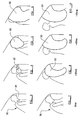
- Figure 3 is a diagrammatic figure illustrating a seat occupant 30 who is out of position, the head of the seat occupant resting on a vehicle dashboard 31.
- Figure 3 illustrates the situation that exists at the commencement of an accident.
- Figure 4 illustrates the situation 25 ms after commencement of the accident.
- the initial stage of inflation of the air-bag has occurred, with gas from the first cell 7 being injected into the air-bag.
- the airbag 32 inflates slowly opening the door of the air-bag housing by about 5 cm and gently moving the head of the seat occupant 30 away from the dashboard. The head of the occupant is not given a violent or sudden acceleration.
- the air-bag 32 continues to inflate until the air-bag has the condition shown in Figure 5 .
- This inflation is achieved with gas from both the first cell 7 and the second cell 8 of the inflator.
- the air-bag inflates more rapidly than during the first phase of inflation, but the air-bag is still not being inflated in a particularly aggressive manner.
- the air-bag inflates towards the occupant. The head of the occupant is thus being given a continuing gentle acceleration.
- the air-bag inflates rapidly to become fully inflated, as shown in Figure 6 .
- the out of position occupant is thus fully protected by the air-bag, but the out of position occupant has not been given an over-severe acceleration.
- the risk of injury to the out of position occupant, even if the out of position occupant is young child, has been minimised.
- the air-bag is fully inflated in 55 ms the air-bag will protect an adult seat occupant adequately.
- Figure 7 to 10 are provided for purposes of comparison and illustrate a conventional air-bag during inflation. As can be seen Figure 7 corresponds directly with Figure 3 showing the out of position occupant at the commencement of the accident.
- the air-bag 33 is fully inflated, and the occupant has been moved to such a position that the head is leaning backwardly, thus risking substantial neck injury.
- the pyrotechnic material may be contained in only two cells, one cell being relatively small and being associated with the squib that is actuated initially in response to a sensed accident situation, the second cell being somewhat larger and being associated with a squib that is actuated at a predetermined period of time after the sensing of an accident situation.
- the burning characteristic of the pyrotechnic material in the second cell is selected to provide an overall inflation characteristic equivalent to that described above.
- the inflator may be a so called “cold” gas generator, which includes one or more bottles containing compressed gas, or may be a “hybrid” inflator in which the inflator includes a combination of bottles containing compressed gas and a pyrotechnic material to generate hot gas.
- an air-bag provided with an inflator in accordance with the invention may be inflated in response to a signal from an accident sensor, the accident sensor providing different signals depending upon the severity of the accident. If a very severe accident is detected all three squibs may be provided with an actuating signal immediately, so that gas generated in all three cells of the gas generator may immediately inflate the air-bag, thus enabling the air-bag to become fully inflated in the least possible time.
Landscapes
- Engineering & Computer Science (AREA)
- Physics & Mathematics (AREA)
- Fluid Mechanics (AREA)
- Mechanical Engineering (AREA)
- General Engineering & Computer Science (AREA)
- Air Bags (AREA)
Claims (10)
- Aufblasvorrichtung (1) für einen Airbag (4), wobei die Aufblasvorrichtung (1) dazu konfiguriert ist, Gas bereitzustellen, um den Airbag (4) aufzublasen, dadurch gekennzeichnet, dass die Aufblaseinrichtung (1) dazu angeordnet und konfiguriert ist, eine erste Gasströmung während einer ersten Betriebsphase bereitzustellen, die eine Dauer von 10 bis 30 ms hat, eine zweite, größere Gasströmung während einer zweiten Betriebsphase, die eine Dauer von 5 bis 15 ms hat, und eine dritte, noch größere Gasströmung während einer weiteren Betriebsphase, wobei die dritte Gasströmung eine vorgegebene Dauer hat, so dass die Gesamtdauer aller drei Stufen zwischen 50 und 70 ms beträgt.
- Aufblasvorrichtung (1) nach Anspruch 1 in Kombination mit einem Airbag (4), wobei der Airbag (4) in einem Gehäuse festgehalten wird, das Gehäuse eine Klappe aufweist, die Aufblasvorrichtung (1) und der Airbag (4) dergestalt sind, dass der Airbag (4) ausreichend aufgeblasen wird, um ein Öffnen der Klappe des Airbaggehäuses auszulösen, die zweite Phase dergestalt ist, dass der Airbag (4) aufgeblasen wird und zumindest ein beträchtlicher Teil des Airbags (4) sich durch die offene Klappe bewegt und der Airbag (4) während der dritten Phase vollständig gefüllt wird.
- Aufblasvorrichtung (1) nach Anspruch 1 oder 2, wobei die Aufblasvorrichtung (1) dergestalt ist, dass, wenn sie innerhalb eines Testtanks mit einer Kapazität von 146 Litern getestet wird, der während der ersten Phase erzeugte Druck zwischen 20 und 30 kPa beträgt, der innerhalb der zweiten Phase erzeugte Druck 40 und 60 kPa beträgt und der in der dritten Phase erzeugte Druck zwischen 150 und 350 kPa beträgt.
- Aufblasvorrichtung (1) nach irgendeinem der vorhergehenden Ansprüche, wobei die Aufblasvorrichtung (1) eine mehrstufige Aufblasvorrichtung ist.
- Aufblasvorrichtung (1) nach irgendeinem der vorhergehenden Ansprüche, wobei die Aufblasvorrichtung (1) eine zweistufige Aufblasvorrichtung ist.
- Aufblasvorrichtung (1) nach irgendeinem der Ansprüche 1 bis 4, wobei die Aufblasvorrichtung (1) eine dreistufige Aufblasvorrichtung ist.
- Aufblasvorrichtung (1) nach Anspruch 6, wobei die Aufblasvorrichtung (1) drei unabhängig ausgelöste pyrotechnische Gas erzeugende Zellen (7, 8, 15) umfasst.
- Aufblasvorrichtung (1) nach Anspruch 7, wobei zwei der Zellen (7, 8) jeweils kleiner als die dritte Zelle (15) sind, die Aufblasvorrichtung (1) so konfiguriert ist, dass eine erste der zwei kleineren Zellen (7, 8) betätigt wird, um die erste Gasströmung bereitzustellen, und eine zweite der zwei kleineren Zellen (7, 8) nach der Betätigung der ersten kleineren Zellen (7, 8) betätigt wird, um die zweite Gasströmung zu erzeugen, und die dritte größere Zelle (15) nach der Betätigung der zwei kleineren Zellen (7, 8) betätigt wird, um die dritte Gasströmung zu erzeugen.
- Aufblasvorrichtung (1) nach irgendeinem der Ansprüche 1 bis 5, wobei die Aufblasvorrichtung (1) Gas erzeugende Einheiten (7, 8, 15) beinhaltet, die Druckgas enthalten.
- Aufblasvorrichtung nach irgendeinem der Ansprüche 1 bis 5, wobei die Aufblasvorrichtung (1) Gas erzeugende Einheiten (7, 8, 15) einschließt, die sowohl pyrotechnische Ladungen (9, 12, 16) als auch Druckgas enthalten.
Applications Claiming Priority (2)
| Application Number | Priority Date | Filing Date | Title |
|---|---|---|---|
| GB0501772A GB2422650B (en) | 2005-01-27 | 2005-01-27 | Improvements in or relating to an air-bag inflator |
| PCT/SE2006/000101 WO2006080881A1 (en) | 2005-01-27 | 2006-01-25 | An air-bag inflator |
Publications (3)
| Publication Number | Publication Date |
|---|---|
| EP1841623A1 EP1841623A1 (de) | 2007-10-10 |
| EP1841623A4 EP1841623A4 (de) | 2010-06-30 |
| EP1841623B1 true EP1841623B1 (de) | 2011-09-07 |
Family
ID=34259812
Family Applications (1)
| Application Number | Title | Priority Date | Filing Date |
|---|---|---|---|
| EP06701487A Revoked EP1841623B1 (de) | 2005-01-27 | 2006-01-25 | Airbag-aufblasvorrichtung |
Country Status (4)
| Country | Link |
|---|---|
| EP (1) | EP1841623B1 (de) |
| AT (1) | ATE523391T1 (de) |
| GB (1) | GB2422650B (de) |
| WO (1) | WO2006080881A1 (de) |
Families Citing this family (1)
| Publication number | Priority date | Publication date | Assignee | Title |
|---|---|---|---|---|
| CN107063615B (zh) * | 2017-02-17 | 2019-03-01 | 南京航空航天大学 | 一种单个砂砾冲蚀用燃气炮试验装置 |
Family Cites Families (7)
| Publication number | Priority date | Publication date | Assignee | Title |
|---|---|---|---|---|
| US5033390A (en) * | 1989-11-13 | 1991-07-23 | Morton International, Inc. | Trilevel performance gas generator |
| US5884939A (en) | 1995-09-22 | 1999-03-23 | Toyo Tire & Rubber Co., Ltd. | Air bag system for automotive passenger seat |
| US6149193A (en) * | 1999-08-06 | 2000-11-21 | Breed Automotive Technology, Inc. | Variable output inflator |
| JP2001163171A (ja) * | 1999-12-10 | 2001-06-19 | Nippon Kayaku Co Ltd | ガス発生器 |
| US6796581B2 (en) * | 2002-03-26 | 2004-09-28 | Intelligent Mechantronic Systems, Inc. | Variable inflation force airbag inflator |
| US6874814B2 (en) * | 2002-06-13 | 2005-04-05 | Key Safety Systems, Inc. | Multiple stage inflator |
| DE20213555U1 (de) * | 2002-09-03 | 2003-10-16 | TRW Airbag Systems GmbH & Co. KG, 84544 Aschau | Gasgenerator |
-
2005
- 2005-01-27 GB GB0501772A patent/GB2422650B/en not_active Expired - Fee Related
-
2006
- 2006-01-25 WO PCT/SE2006/000101 patent/WO2006080881A1/en not_active Ceased
- 2006-01-25 EP EP06701487A patent/EP1841623B1/de not_active Revoked
- 2006-01-25 AT AT06701487T patent/ATE523391T1/de not_active IP Right Cessation
Also Published As
| Publication number | Publication date |
|---|---|
| EP1841623A1 (de) | 2007-10-10 |
| EP1841623A4 (de) | 2010-06-30 |
| GB0501772D0 (en) | 2005-03-02 |
| GB2422650A (en) | 2006-08-02 |
| ATE523391T1 (de) | 2011-09-15 |
| GB2422650B (en) | 2007-10-03 |
| WO2006080881A1 (en) | 2006-08-03 |
Similar Documents
| Publication | Publication Date | Title |
|---|---|---|
| JP3040516U (ja) | 能力調整可能なハイブリッドインフレータ | |
| US6536799B2 (en) | Safety device with an airbag configuration including multiple airbags for a motor vehicle | |
| KR100517749B1 (ko) | 빈 가요성 컨테이너 충전 방법 및 컨테이너 장치 | |
| US5513879A (en) | Two stage inflator with module venting for passenger side airbags | |
| US5820162A (en) | Airbag system inflator | |
| EP0405710B1 (de) | Gassack-Aufprallschutzvorrichtung | |
| EP1056624B2 (de) | Aufblasvorrichtung mit adaptativem gassfluss | |
| US6820898B2 (en) | Biaxial dual stage inflator with extended gas delivery for a vehicular airbag system | |
| US7004500B2 (en) | Dual stage inflator with extended gas delivery for a vehicular airbag system | |
| EP0734919A1 (de) | Druckgas-Aufblasvorrichtung für Fahrzeuginsassen-Schutzsysteme | |
| JP2006522715A (ja) | 自動車のエアバッグシステム用火薬式インフレータ | |
| JP3082426B2 (ja) | エアバッグ用インフレータ | |
| GB2357465A (en) | Inflatable metal air bag with enclosed gas generator | |
| US20040124619A1 (en) | Adaptive output airbag inflation device | |
| US6196582B1 (en) | Variable output inflator for an air bag | |
| US7316417B2 (en) | Inflator with internally mounted initiator | |
| JP3664878B2 (ja) | 自動車の乗員保持装置 | |
| JPH0790744B2 (ja) | 乗員保護用エアバッグ装置 | |
| GB2323568A (en) | Reducing airbag forward speed | |
| EP1841623A1 (de) | Airbag-aufblasvorrichtung | |
| WO2000021799A1 (en) | Flow regulated inflator | |
| JPH0640043Y2 (ja) | エアバッグ装置 | |
| WO2013123371A1 (en) | Shockwave generating mechanism for automotive inflator deployment | |
| WO2000021800A9 (en) | Vortex valve inflator for inflatable restraint system | |
| GB2443614A (en) | Airbag with secondary chamber opening door |
Legal Events
| Date | Code | Title | Description |
|---|---|---|---|
| PUAI | Public reference made under article 153(3) epc to a published international application that has entered the european phase |
Free format text: ORIGINAL CODE: 0009012 |
|
| 17P | Request for examination filed |
Effective date: 20070702 |
|
| AK | Designated contracting states |
Kind code of ref document: A1 Designated state(s): AT BE BG CH CY CZ DE DK EE ES FI FR GB GR HU IE IS IT LI LT LU LV MC NL PL PT RO SE SI SK TR |
|
| RIC1 | Information provided on ipc code assigned before grant |
Ipc: B60R 21/264 20060101AFI20071114BHEP |
|
| DAX | Request for extension of the european patent (deleted) | ||
| A4 | Supplementary search report drawn up and despatched |
Effective date: 20100602 |
|
| REG | Reference to a national code |
Ref country code: DE Ref legal event code: R079 Ref document number: 602006024175 Country of ref document: DE Free format text: PREVIOUS MAIN CLASS: B60R0021000000 Ipc: B60R0021264000 |
|
| GRAP | Despatch of communication of intention to grant a patent |
Free format text: ORIGINAL CODE: EPIDOSNIGR1 |
|
| RIC1 | Information provided on ipc code assigned before grant |
Ipc: B60R 21/264 20060101AFI20110202BHEP |
|
| GRAS | Grant fee paid |
Free format text: ORIGINAL CODE: EPIDOSNIGR3 |
|
| GRAA | (expected) grant |
Free format text: ORIGINAL CODE: 0009210 |
|
| REG | Reference to a national code |
Ref country code: GB Ref legal event code: FG4D |
|
| REG | Reference to a national code |
Ref country code: CH Ref legal event code: EP |
|
| REG | Reference to a national code |
Ref country code: IE Ref legal event code: FG4D |
|
| REG | Reference to a national code |
Ref country code: DE Ref legal event code: R096 Ref document number: 602006024175 Country of ref document: DE Effective date: 20111103 |
|
| REG | Reference to a national code |
Ref country code: NL Ref legal event code: VDEP Effective date: 20110907 |
|
| PG25 | Lapsed in a contracting state [announced via postgrant information from national office to epo] |
Ref country code: SE Free format text: LAPSE BECAUSE OF FAILURE TO SUBMIT A TRANSLATION OF THE DESCRIPTION OR TO PAY THE FEE WITHIN THE PRESCRIBED TIME-LIMIT Effective date: 20110907 Ref country code: LT Free format text: LAPSE BECAUSE OF FAILURE TO SUBMIT A TRANSLATION OF THE DESCRIPTION OR TO PAY THE FEE WITHIN THE PRESCRIBED TIME-LIMIT Effective date: 20110907 Ref country code: FI Free format text: LAPSE BECAUSE OF FAILURE TO SUBMIT A TRANSLATION OF THE DESCRIPTION OR TO PAY THE FEE WITHIN THE PRESCRIBED TIME-LIMIT Effective date: 20110907 |
|
| LTIE | Lt: invalidation of european patent or patent extension |
Effective date: 20110907 |
|
| PG25 | Lapsed in a contracting state [announced via postgrant information from national office to epo] |
Ref country code: CY Free format text: LAPSE BECAUSE OF FAILURE TO SUBMIT A TRANSLATION OF THE DESCRIPTION OR TO PAY THE FEE WITHIN THE PRESCRIBED TIME-LIMIT Effective date: 20110907 Ref country code: AT Free format text: LAPSE BECAUSE OF FAILURE TO SUBMIT A TRANSLATION OF THE DESCRIPTION OR TO PAY THE FEE WITHIN THE PRESCRIBED TIME-LIMIT Effective date: 20110907 Ref country code: SI Free format text: LAPSE BECAUSE OF FAILURE TO SUBMIT A TRANSLATION OF THE DESCRIPTION OR TO PAY THE FEE WITHIN THE PRESCRIBED TIME-LIMIT Effective date: 20110907 Ref country code: LV Free format text: LAPSE BECAUSE OF FAILURE TO SUBMIT A TRANSLATION OF THE DESCRIPTION OR TO PAY THE FEE WITHIN THE PRESCRIBED TIME-LIMIT Effective date: 20110907 Ref country code: GR Free format text: LAPSE BECAUSE OF FAILURE TO SUBMIT A TRANSLATION OF THE DESCRIPTION OR TO PAY THE FEE WITHIN THE PRESCRIBED TIME-LIMIT Effective date: 20111208 |
|
| REG | Reference to a national code |
Ref country code: AT Ref legal event code: MK05 Ref document number: 523391 Country of ref document: AT Kind code of ref document: T Effective date: 20110907 |
|
| PG25 | Lapsed in a contracting state [announced via postgrant information from national office to epo] |
Ref country code: BE Free format text: LAPSE BECAUSE OF FAILURE TO SUBMIT A TRANSLATION OF THE DESCRIPTION OR TO PAY THE FEE WITHIN THE PRESCRIBED TIME-LIMIT Effective date: 20110907 |
|
| PG25 | Lapsed in a contracting state [announced via postgrant information from national office to epo] |
Ref country code: CZ Free format text: LAPSE BECAUSE OF FAILURE TO SUBMIT A TRANSLATION OF THE DESCRIPTION OR TO PAY THE FEE WITHIN THE PRESCRIBED TIME-LIMIT Effective date: 20110907 Ref country code: IS Free format text: LAPSE BECAUSE OF FAILURE TO SUBMIT A TRANSLATION OF THE DESCRIPTION OR TO PAY THE FEE WITHIN THE PRESCRIBED TIME-LIMIT Effective date: 20120107 Ref country code: SK Free format text: LAPSE BECAUSE OF FAILURE TO SUBMIT A TRANSLATION OF THE DESCRIPTION OR TO PAY THE FEE WITHIN THE PRESCRIBED TIME-LIMIT Effective date: 20110907 |
|
| PG25 | Lapsed in a contracting state [announced via postgrant information from national office to epo] |
Ref country code: PT Free format text: LAPSE BECAUSE OF FAILURE TO SUBMIT A TRANSLATION OF THE DESCRIPTION OR TO PAY THE FEE WITHIN THE PRESCRIBED TIME-LIMIT Effective date: 20120109 Ref country code: NL Free format text: LAPSE BECAUSE OF FAILURE TO SUBMIT A TRANSLATION OF THE DESCRIPTION OR TO PAY THE FEE WITHIN THE PRESCRIBED TIME-LIMIT Effective date: 20110907 Ref country code: IT Free format text: LAPSE BECAUSE OF FAILURE TO SUBMIT A TRANSLATION OF THE DESCRIPTION OR TO PAY THE FEE WITHIN THE PRESCRIBED TIME-LIMIT Effective date: 20110907 Ref country code: RO Free format text: LAPSE BECAUSE OF FAILURE TO SUBMIT A TRANSLATION OF THE DESCRIPTION OR TO PAY THE FEE WITHIN THE PRESCRIBED TIME-LIMIT Effective date: 20110907 Ref country code: PL Free format text: LAPSE BECAUSE OF FAILURE TO SUBMIT A TRANSLATION OF THE DESCRIPTION OR TO PAY THE FEE WITHIN THE PRESCRIBED TIME-LIMIT Effective date: 20110907 Ref country code: EE Free format text: LAPSE BECAUSE OF FAILURE TO SUBMIT A TRANSLATION OF THE DESCRIPTION OR TO PAY THE FEE WITHIN THE PRESCRIBED TIME-LIMIT Effective date: 20110907 |
|
| PLBI | Opposition filed |
Free format text: ORIGINAL CODE: 0009260 |
|
| PLAZ | Examination of admissibility of opposition: despatch of communication + time limit |
Free format text: ORIGINAL CODE: EPIDOSNOPE2 |
|
| PLBA | Examination of admissibility of opposition: reply received |
Free format text: ORIGINAL CODE: EPIDOSNOPE4 |
|
| PLAX | Notice of opposition and request to file observation + time limit sent |
Free format text: ORIGINAL CODE: EPIDOSNOBS2 |
|
| 26 | Opposition filed |
Opponent name: TRW AIRBAG SYSTEMS GMBH Effective date: 20120606 |
|
| PG25 | Lapsed in a contracting state [announced via postgrant information from national office to epo] |
Ref country code: DK Free format text: LAPSE BECAUSE OF FAILURE TO SUBMIT A TRANSLATION OF THE DESCRIPTION OR TO PAY THE FEE WITHIN THE PRESCRIBED TIME-LIMIT Effective date: 20110907 |
|
| PG25 | Lapsed in a contracting state [announced via postgrant information from national office to epo] |
Ref country code: MC Free format text: LAPSE BECAUSE OF NON-PAYMENT OF DUE FEES Effective date: 20120131 |
|
| REG | Reference to a national code |
Ref country code: CH Ref legal event code: PL |
|
| REG | Reference to a national code |
Ref country code: DE Ref legal event code: R026 Ref document number: 602006024175 Country of ref document: DE Effective date: 20120606 |
|
| GBPC | Gb: european patent ceased through non-payment of renewal fee |
Effective date: 20120125 |
|
| REG | Reference to a national code |
Ref country code: FR Ref legal event code: ST Effective date: 20120928 |
|
| REG | Reference to a national code |
Ref country code: IE Ref legal event code: MM4A |
|
| PLAF | Information modified related to communication of a notice of opposition and request to file observations + time limit |
Free format text: ORIGINAL CODE: EPIDOSCOBS2 |
|
| PG25 | Lapsed in a contracting state [announced via postgrant information from national office to epo] |
Ref country code: LI Free format text: LAPSE BECAUSE OF NON-PAYMENT OF DUE FEES Effective date: 20120131 Ref country code: GB Free format text: LAPSE BECAUSE OF NON-PAYMENT OF DUE FEES Effective date: 20120125 Ref country code: CH Free format text: LAPSE BECAUSE OF NON-PAYMENT OF DUE FEES Effective date: 20120131 |
|
| PG25 | Lapsed in a contracting state [announced via postgrant information from national office to epo] |
Ref country code: FR Free format text: LAPSE BECAUSE OF NON-PAYMENT OF DUE FEES Effective date: 20120131 |
|
| PG25 | Lapsed in a contracting state [announced via postgrant information from national office to epo] |
Ref country code: IE Free format text: LAPSE BECAUSE OF NON-PAYMENT OF DUE FEES Effective date: 20120125 |
|
| PG25 | Lapsed in a contracting state [announced via postgrant information from national office to epo] |
Ref country code: ES Free format text: LAPSE BECAUSE OF FAILURE TO SUBMIT A TRANSLATION OF THE DESCRIPTION OR TO PAY THE FEE WITHIN THE PRESCRIBED TIME-LIMIT Effective date: 20111218 |
|
| PGFP | Annual fee paid to national office [announced via postgrant information from national office to epo] |
Ref country code: DE Payment date: 20121114 Year of fee payment: 8 |
|
| PG25 | Lapsed in a contracting state [announced via postgrant information from national office to epo] |
Ref country code: BG Free format text: LAPSE BECAUSE OF FAILURE TO SUBMIT A TRANSLATION OF THE DESCRIPTION OR TO PAY THE FEE WITHIN THE PRESCRIBED TIME-LIMIT Effective date: 20111207 |
|
| PG25 | Lapsed in a contracting state [announced via postgrant information from national office to epo] |
Ref country code: TR Free format text: LAPSE BECAUSE OF FAILURE TO SUBMIT A TRANSLATION OF THE DESCRIPTION OR TO PAY THE FEE WITHIN THE PRESCRIBED TIME-LIMIT Effective date: 20110907 |
|
| RDAF | Communication despatched that patent is revoked |
Free format text: ORIGINAL CODE: EPIDOSNREV1 |
|
| PG25 | Lapsed in a contracting state [announced via postgrant information from national office to epo] |
Ref country code: LU Free format text: LAPSE BECAUSE OF NON-PAYMENT OF DUE FEES Effective date: 20120125 |
|
| PG25 | Lapsed in a contracting state [announced via postgrant information from national office to epo] |
Ref country code: HU Free format text: LAPSE BECAUSE OF FAILURE TO SUBMIT A TRANSLATION OF THE DESCRIPTION OR TO PAY THE FEE WITHIN THE PRESCRIBED TIME-LIMIT Effective date: 20060125 |
|
| REG | Reference to a national code |
Ref country code: DE Ref legal event code: R119 Ref document number: 602006024175 Country of ref document: DE |
|
| RDAG | Patent revoked |
Free format text: ORIGINAL CODE: 0009271 |
|
| STAA | Information on the status of an ep patent application or granted ep patent |
Free format text: STATUS: PATENT REVOKED |
|
| 27W | Patent revoked |
Effective date: 20140605 |
|
| REG | Reference to a national code |
Ref country code: DE Ref legal event code: R119 Ref document number: 602006024175 Country of ref document: DE Effective date: 20140801 |