EP1841987B1 - Variator für ein stufenloses getriebe - Google Patents
Variator für ein stufenloses getriebe Download PDFInfo
- Publication number
- EP1841987B1 EP1841987B1 EP05850168A EP05850168A EP1841987B1 EP 1841987 B1 EP1841987 B1 EP 1841987B1 EP 05850168 A EP05850168 A EP 05850168A EP 05850168 A EP05850168 A EP 05850168A EP 1841987 B1 EP1841987 B1 EP 1841987B1
- Authority
- EP
- European Patent Office
- Prior art keywords
- transmission
- variator
- ring
- axis
- rotational axis
- Prior art date
- Legal status (The legal status is an assumption and is not a legal conclusion. Google has not performed a legal analysis and makes no representation as to the accuracy of the status listed.)
- Expired - Lifetime
Links
Images

Classifications
-
- F—MECHANICAL ENGINEERING; LIGHTING; HEATING; WEAPONS; BLASTING
- F16—ENGINEERING ELEMENTS AND UNITS; GENERAL MEASURES FOR PRODUCING AND MAINTAINING EFFECTIVE FUNCTIONING OF MACHINES OR INSTALLATIONS; THERMAL INSULATION IN GENERAL
- F16H—GEARING
- F16H15/00—Gearings for conveying rotary motion with variable gear ratio, or for reversing rotary motion, by friction between rotary members
- F16H15/02—Gearings for conveying rotary motion with variable gear ratio, or for reversing rotary motion, by friction between rotary members without members having orbital motion
- F16H15/04—Gearings providing a continuous range of gear ratios
- F16H15/06—Gearings providing a continuous range of gear ratios in which a member A of uniform effective diameter mounted on a shaft may co-operate with different parts of a member B
- F16H15/32—Gearings providing a continuous range of gear ratios in which a member A of uniform effective diameter mounted on a shaft may co-operate with different parts of a member B in which the member B has a curved friction surface formed as a surface of a body of revolution generated by a curve which is neither a circular arc centered on its axis of revolution nor a straight line
- F16H15/36—Gearings providing a continuous range of gear ratios in which a member A of uniform effective diameter mounted on a shaft may co-operate with different parts of a member B in which the member B has a curved friction surface formed as a surface of a body of revolution generated by a curve which is neither a circular arc centered on its axis of revolution nor a straight line with concave friction surface, e.g. a hollow toroid surface
Definitions
- the invention relates to a variator unit for a continuously variable transmission, in particular a CVT transmission according to the preamble of claim 1.
- the variator in such a transmission serves to transmit the torque of an input shaft to an output shaft, wherein the transmission ratio between the input shaft and the output shaft is freely adjustable within a translation range.
- Known variators for continuously variable transmissions use chains or metallic bands which engage, for example, with conical transfer surfaces on the input and output shafts.
- the generic German patent application DE 198 04 011 A1 discloses a continuously variable pitch gear having at least one cone pulley, a group of rotatably mounted planetary rollers each having at least one tapered tread, with at least one group of double tapered rotatably and longitudinally displaceably mounted intermediate rollers disposed between the planetary rollers and the cone pulley, the pulley discs , The planetary rollers and the intermediate rollers are arranged rotationally symmetrical with respect to the transmission longitudinal axis.
- the mutually facing running surfaces of the conical disk and the planetary rollers are designed such that the extending in sectional planes through the longitudinal axis transmission lines of these treads are oriented parallel to each other, wherein the axes of rotation of the intermediate roles relative to the falling lines of each associated tapered running surfaces of the conical disk and the planetary rollers are arranged at an angle, and wherein the axes of rotation of all intermediate rollers of each intermediate roller group are displaceable with respect to the conical disk and the planetary rollers parallel to the transmission longitudinal axis while changing the transmission ratio of the Wälzgetriebes.
- a so-called cone ring variator which also manages without a chain or metallic band, but works with a rigid transfer ring.
- the spread of the translation is limited by the ratio between the smallest and the largest diameter of the cone.
- the invention is based on the idea to avoid the very complex design of a chain for variators, which has a complex and complicated geometry due to many links and is relatively loud in operation, inter alia, by the movement of the chain links relative to each other. Therefore, a rigid ring member is used as the transmission element, which is easy to manufacture. Therefore, operating noise caused by the chain links and in particular their mobility to each other avoided.
- a pairing of a convex and a concave transfer surface is selected, along which a transfer ring is displaceable.
- the variator for a continuously variable transmission sees around a first axis of rotation rotatable first transmission element with a convex curved, rotationally symmetrical about the first axis of rotation transmission surface, a second rotatable about a second axis of rotation transmission element with a concave curved, rotationally symmetrical about the second axis of rotation transmission surface and a rigid Transmission ring which is adjustable in its relative position to the transfer surfaces within an adjustment range and can be pressed against both transfer surfaces and transmits a torque between the first and the second transfer surface.
- the cut lines of the transfer surfaces with a plane spanned by the axes of rotation are parallel at least in the adjustment range of the transfer ring.
- at least the first or the second transmission element in the axial direction of its axis of rotation is displaceable. This ensures a good contact pressure of the transfer ring to the transfer surfaces.
- the convex curved transfer surface is a spherical surface and the concave curved transfer surface is a toroidal surface. This arrangement allows particularly large spreads, so that the transmission ratio is sensitive to a movement of the transmission ring.
- the spherical surface and the generative circle of the toroidal surface have equal centers, and the radius r2 of the toroidal surface is the sum of the radius r1 of the spherical surface and d, where d is the smallest distance between the toroidal surface and the spherical surface. This smallest distance d is also in the cutting plane, which is spanned by the two axes of rotation of the first transmission element and the second transmission element.
- the transmission ring then has the width d.
- the center of the transmission ring which is preferably a circular ring, lies on the extension of the radii of the spherical surface and of the generating circle of the toroidal surface.
- This can be a good contact pressure and easy adjustment of the ring by tilting the ring from the position in which it is perpendicular to the tangent at the points of contact with the transfer surfaces, guaranteed.
- the arrangement further comprises an adjusting device for adjusting the transmission ring, which first deflects the transmission ring in a Vorstellvorgang from its position perpendicular to the transfer surfaces position. Due to the inclination of the ring with respect to the transfer surfaces, the ring can freely position itself in dependence on the direction of movement of an accelerator pedal.
- the torque required for adjustment is supplied by a motor, such as an electric motor from the outside.
- the convex transfer surface in particular a spherical surface, on the input transfer element and the concave transfer surface, in particular the Toroidal Structure, provided on the output transfer element.
- the axes of rotation of the first and the second transmission element are parallel to each other. As a result, good contact pressure between the transfer surfaces and reliable torque transfer can be ensured.
- a variator arrangement which contains a plurality of variators with the mentioned features.
- two axially symmetrically arranged variators are provided, wherein the axis of symmetry of the arrangement is perpendicular to the mutually parallel axes of rotation of the transmission elements.
- four variators are preferably provided, the variators being arranged axially symmetrically with respect to an axis of symmetry perpendicular to the parallel axes of rotation of the transmission elements and axisymmetrically with respect to the common axis of rotation of the transmission elements with the concave transmission surfaces.
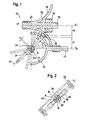
- Fig. 1 a cross-sectional view through a variator according to an embodiment of the invention is shown.
- the cross-sectional plane is the plane in which the elements transmitting the moment between the input and output shafts abut each other.
- the variator 10 includes a first shaft 12 which is rotatably mounted in a housing (not shown) about the axis of rotation x.
- a first transfer surface 14 is provided, which is rotatably connected to the shaft 12 and is manufactured integrally therewith.
- the first transfer surface is formed by the outer surface of a portion of a sphere, approximately a hemisphere, which adjoins the rotation shaft 12 so that the rotational symmetry axis of the spherical surface coincides with the axis of rotation x.
- the spherically curved transfer surface 14 is connected to the shaft 12 so as to be convex toward the shaft 12.
- the spherical surface has a radius r1.
- the first transfer surface is at least designed as the part of a sphere corresponding to a hemisphere, so that the variation of the radius of an imaginary ring running along the hemisphere with center on the x-axis and perpendicular to the x-axis for varying the transmission ratio can be utilized.
- the radius n1 of this ring which corresponds to the first kinematic radius of the variator, thus varies in the range 0 ⁇ n1 ⁇ r1.
- the substantially hemispherical first transfer surface 14 Upon rotation of the shaft 12 about the axis x, the substantially hemispherical first transfer surface 14 also rotates and also rotates about the axis x.
- the variator 10 further includes a second shaft 16, whose axis x1 is arranged parallel to the axis x of the first shaft 12.
- the shaft 16 is also supported for rotation in the housing (not shown). With the second shaft 16 rotatably connected or made integral with it is a second transfer surface 18th
- the second transfer surface 18 is formed as part of a torus surface, wherein the generatrix of the torus has the same center O as the hemispherical first transfer surface 14, a radius r2 greater than the radius r1 of the hemispherical transfer surface 14 by a distance d, and the generation axis the axis x1, ie the axis of rotation of the second transmission element has.
- the transfer surface 18 of the second transfer element is generated by the part of a Torus transformation corresponding to a rotation of approximately a quarter circle with said radius and said center about the axis x1, wherein the quadrant starting from a point at which the tangent of Quarter circle parallel to the axis x1 and closest to this, by 90 ° to an end point in the vicinity of the first wave extends such that the generating quadrant parallel to the hemisphere of the first transfer surface in the in Fig. 1 is shown level.
- the second transfer surface 18 is preferably connected to the shaft 16, but the connection also extends over an axially wider region than in FIG Fig. 1 can be made.
- the shaft 16 remote from the surface of the torus, ie, the convex surface 14 facing concave Toroidal Structure 18. It is essential that in the in Fig. 1 Section shown, that is, the plane containing the axes of rotation x, x1, at least in a portion of the gap formed between the transfer surfaces 14, 18 gap width d and thus parallel interfaces, ie that in the sectional plane, the transfer surface 18 and the transfer surface 14 at least along a Line are parallel to each other.
- the cutting plane corresponds to the plane in which the force and torque transmission takes place.
- the annular transfer member extends through the region between the concave and convex transfer surfaces including the gap having the width d.
- the transmission ring 20 is designed as a rigid element in a circular ring shape and has a center 03, which lies on the extension of the radii of the spherical first transfer surface 14 and the toroidal second transfer surface 18, wherein with respect to the common center point of the spherical surface generating circle with the radius r1 and the circle of correspondence of the toroidal surface r2 is offset by a distance e.
- the wall thickness of the ring corresponds to the difference d between r1 and r2, so that the ring can be in good contact with the first and the second transfer surface when aligned in the radial direction.
- the ring 20 is by means of an adjusting device 22, which is supported by the bearing 24 on the housing (not shown) to the z-axis (axis perpendicular to the plane in FIG Fig. 1 and to the plane spanned by the axes x1, x through the center point 0 of the toroidal surface generating circuit, and thus its abutment point with the transfer surfaces 14, 18 within the gap between the first transfer surface 14 and the second transfer surface 18 is formed, slidable over an adjustment.
- the adjustment range of the transmission ring results as the pivoting range of the ring about the axis z, ie, by an angle range of 0 ⁇ ⁇ 90 ° with respect to the x axis.
- a gear ratio between the rotational speed of the input shaft x and the output shaft x1 is set.
- the gear ratio is a function of the kinematic radii n1 and n2, which in each case as a vertical distance of the contact point of the transfer ring 20 on the first transfer surface 14 to the axis x (n1) or as a vertical distance of the contact point of the transfer ring 20 on the second transfer surface 18 to Axis x1 (n2) can be determined.
- the ring 20 To adjust the ring, the ring 20 must be rotated about the z-axis.
- the torque required for rotation about the z-axis can be generated for example by means of an electric motor from the outside.
- the ring 20 if an adjustment is required by means of the adjusting device 22 initially tilted from its position perpendicular to the tangent to the transfer surfaces 14, 18 in the contact point. The ring then automatically travels through the rotation of the transfer surfaces until it has reached the new position provided by the gearbox control and re-establishes itself there in the position perpendicular to the tangent to the transfer surfaces 14, 18 in the new contact point. In the latter case, the torque of the drive motor is used for adjustment.
- the tilting of the ring 20 from this position is achieved by the adjusting device 22, which in Fig. 2 is shown.
- the adjusting device 22 which in Fig. 2 is shown.
- the cylinder member 26 rotates about a pin 28 which is fixedly connected to a shaft 30 having its axis of rotation in the z-direction.
- the frame 22 rotates the ring 20 about the radial axis of the ring through the contact point to the transmission surfaces extending axis e3 and thus tilts the ring.
- the ring 20 begins to rotate about the z axis until the gas pedal stops moving. Depending on the position of the ring thus varies the translation, depending on how fast and how far the accelerator pedal is actuated.
- the ring 20 rests with its outer peripheral surface on the concave transfer surface 18 and with its inner peripheral surface on the convex transfer surface 14.
- the shaft 16 is mounted displaceably in the axial direction and biased in the pressing direction, so that always a good contact pressure is ensured.
- the shaft 12 could be slidably mounted in the axial direction. The pressing direction is always such that the distance between the transfer surfaces is reduced.
- the movement of the displaceable shaft 16 in the axial direction can be generated by oil under pressure between the disks which form the transfer surfaces 14, 18 and their storage.
- the chamber 32 to be supplied or removed, which is bounded by the transfer surface 18 side facing away from the disc, the shaft 16 and the bearing 34 for the shaft 16.
- the pressure in the chamber 32 can be controlled, for example, by a moment sensor with balls on inclined tracks in dependence on the moment of resistance. Thus, it is possible to load the variator in each operating situation with the appropriate pressure.
- first transfer surface 14 and the toroidal surface 18 it is also possible to select transfer surfaces which do not have circular, but for example oval or elliptical bases as generators, as long as it is ensured that the walls of the convex transfer surface and the concave transfer surface at least in the plane, which is spanned by the axes x, x1, run parallel, so that a gap d is generated in which the transmission element, which is designed as a rigid transmission ring 20, is adjustably mounted and can be pressed against the transmission surfaces.
- the pairing of toroidal surface and spherical surface simplifies the control for setting the transmission ratio, since the surface curvatures and thus the variation of the kinematic radii depending on the position of the transmission ring can be well represented.
- it can be achieved in any position along the spherical surface and the Toroidal Chemistry the contact pressure on the ring by the ring only about an axis perpendicular to the plane in Fig. 1 is turned.
- FIG. 3 and 4 arrangements are shown in which a plurality of variators 10 according to Fig. 1 are assembled to a variator assembly 40.
- the convex transfer surfaces sit 14 at the in Fig. 3 illustrated embodiment on a common input shaft 12 and are positioned mirror images of each other, wherein the plane of symmetry is perpendicular to the axes x, x1.
- the concave transfer surfaces are also mirror images of each other with respect to this plane, wherein the rotation axis x1 is again parallel to the axis x and both second transfer surfaces 18 have a common axis of rotation x1.
- the transmission surfaces 18 are slidable with respect to each other in the axial direction to ensure sufficient contact pressure against the respective convex transmission surfaces 14.
- the output shaft 16 is provided with a coupling element 36 which allows axial displacement, but can transmit rotational forces.
- a ring member 20 is provided, which is associated with an adjusting mechanism 22.
- FIG Fig. 4 An alternative arrangement in which a plurality of variators 10 are also mounted in parallel is shown in FIG Fig. 4 shown, wherein the arrangement is essentially the arrangement of Fig. 3 corresponds and two further variators 10 are arranged symmetrically with respect to the x1-axis, ie the axis of rotation of the output shaft.
Landscapes
- Engineering & Computer Science (AREA)
- General Engineering & Computer Science (AREA)
- Mechanical Engineering (AREA)
- Friction Gearing (AREA)
- Transmission Devices (AREA)
- Valve Device For Special Equipments (AREA)
Description
- Die Erfindung betrifft eine Variatoreinheit für ein stufenloses Getriebe, insbesondere ein CVT-Getriebe entsprechend dem Oberbegriff des Anspruchs 1. Der Variator in einem solchen Getriebe dient dazu, das Drehmoment einer Eingangswelle auf eine Ausgangswelle zu übertragen, wobei das Übersetzungsverhältnis zwischen der Eingangswelle und der Ausgangswelle innerhalb eines Übersetzungsbereiches frei einstellbar ist.
- Bei bekannten Variatoren für stufenlos einstellbare Getriebe werden Ketten oder metallische Bänder verwendet, welche beispielsweise mit kegelförmigen Übertragungsflächen an der Ein-und Ausgangswelle in Eingriff sind.
- Außerdem ist es bekannt, Variatoren für CVT-Getriebe ohne Ketten oder metallische Bänder vorzusehen. Beispielsweise gibt es sogenannte "Half-Toroidal-CVT's", bei welchen die Bewegung zwischen zwei Toroidalflächen mittels einer verstellbaren Zwischenscheibe übertragen wird. Die Kraftübertragung benötigt dabei hohe Anpresskräfte, was wiederum zu großen zunehmenden Reaktionskräften in den Elementpaarungen des Variators führt. Daher werden bei solchen aus zwischen zwei Toroidalflächen das Drehmoment übertragenden Variatoren mehrere Zwischenscheiben zwischen den Toroidal-Scheiben montiert und/oder mehrere Variatoren parallel montiert, damit die hohen Anpresskräfte reduziert und / oder höhere Drehmomente übertragen werden können.
- Die gattungsgemäße deutsche Offenlegungsschrift
DE 198 04 011 A1 offenbart ein stufenlos verstellbares Wälzgetriebe mit zumindest einer Kegelscheibe, einer Gruppe drehbar gelagerter Planetenrollen, welche jeweils wenigstens eine kegelige Lauffläche aufweisen, mit zumindest einer Gruppe von doppelkegelförmigen, drehbar und längsverschieblich gelagerten Zwischenrollen, welche zwischen den Planetenrollen und der Kegelscheibe angeordnet sind, wobei die Kegelscheiben, die Planetenrollen und die Zwischenrollen rotationssymmetrisch bezüglich der Getriebelängsachse angeordnet sind. Dabei sind die einander zugewandten Laufflächen der Kegelscheibe und der Planetenrollen derart ausgebildet, dass die in Schnittebenen durch die Getriebelängsachse verlaufenden Falllinien dieser Laufflächen parallel zueinander orientiert sind, wobei die Drehachsen der Zwischenrollen gegenüber den Falllinien von jeweils zugeordneten kegeligen Laufflächen der Kegelscheibe und der Planetenrollen unter einem Winkel angeordnet sind, und wobei die Drehachsen aller Zwischenrollen jeder Zwischenrollengruppe gemeinsam bezüglich der Kegelscheibe und der Planetenrollen parallel zur Getriebelängsachse unter Änderung des Übersetzungsverhältnisses des Wälzgetriebes verschiebbar sind. - Als Alternative dazu ist ein sogenannter Kegelringvariator bekannt, welcher ebenfalls ohne Kette oder metallisches Band auskommt, sondern mit einem starren Übertragungsring arbeitet. Dabei wird das Drehmoment zwischen zwei zueinander entgegengesetzt konusförmigen Flächen, die mittels zueinander paralleler Achsen drehbar gelagert sind, mittels einer Ringscheibe übertragen. Die Spreizung der Übersetzung wird durch das Verhältnis zwischen kleinstem und größtem Durchmesser der Kegel limitiert.
- Es ist Aufgabe der Erfindung, einen Variator für ein stufenlos verstellbares Getriebe, insbesondere ein CVT-Getriebe, vorzusehen, welcher eine hohe Spreizung der Übersetzung erlaubt und leise arbeitet. Gleichzeitig soll der Variator kostengünstig herstellbar sein.
- Diese Aufgabe wird mit einem Variator mit den Merkmalen des Anspruchs 1 gelöst. Bevorzugte Ausführungsformen und Weiterbildungen sind in den abhängigen Ansprüchen angegeben.
- Der Erfindung liegt der Gedanke zugrunde, die sehr aufwendige Gestaltung einer Kette für Variatoren zu vermeiden, die auf Grund vieler Kettenglieder eine komplexe und komplizierte Geometrie aufweist und im Betrieb u.a. durch die Bewegung der Kettenglieder relativ zueinander verhältnismäßig laut ist. Daher wird als Übertragungselement ein starres Ringelement verwendet, das einfach herzustellen ist. Daher werden Betriebsgeräusche, die durch die Kettenglieder und insbesondere deren Beweglichkeit zueinander entstehen, vermieden. Um gleichzeitig hohe Spreizungen im Variator vorsehen zu können, wird eine Paarung aus einer konvex und einer konkav gewölbten Übertragungsfläche gewählt, entlang derer ein Übertragungsring verschiebbar ist. Da die Anlagepunkte des Übertragungsrings an die Übertragungsflächen nicht auf einer geradlinigen Bahn, sondern einer gekrümmten Bahn liegen und somit die für das Übersetzungsverhältnis ausschlaggebende kinematischen Radien stärker als linear der Krümmung entsprechend variieren, werden Spreizungen der Übersetzung über einen weiten Bereich ermöglicht. Außerdem wird durch die Kombination aus konvexer und konkaver Übertragungsfläche erreicht, dass bereits eine Verstellung des Übertragungsrings um einen kurzen Weg zu einer deutlichen Veränderung des Übertragungsverhältnisses führt, da die Veränderung der kinematischen Radien des Variators nicht linear verläuft.
- Somit sieht der Variator für ein stufenloses Getriebe ein um eine erste Drehachse drehbares erstes Übertragungselement mit einer konvex gekrümmten, um die erste Drehachse rotationssymmetrischen Übertragungsfläche, ein zweites um eine zweite Drehachse drehbares Übertragungselement mit einer konkav gekrümmten, um die zweite Drehachse rotationssymmetrischen Übertragungsfläche und einen starren Übertragungsring vor, der in seiner Relativposition zu den Übertragungsflächen innerhalb eines Verstellbereiches verstellbar und an beide Übertragungsflächen anpressbar ist und ein Drehmoment zwischen der ersten und der zweiten Übertragungsfläche überträgt. Die Schnittlinien der Übertragungsflächen mit einer durch die Drehachsen aufgespannten Ebene sind zumindest im Verstellbereich des Übertragungsrings parallel. Dabei ist mindestens das erste oder das zweite Übertragungselement in Axialrichtung seiner Drehachse verschiebbar. Dadurch kann eine gute Anpressung des Übertragungsrings an die Übertragungsflächen sichergestellt werden.
- Vorzugsweise ist die konvex gekrümmte Übertragungsfläche eine sphärische Fläche und die konkav gekrümmte Übertragungsfläche eine Toroidalfläche. Diese Anordnung erlaubt besonders große Spreizungen, so dass das Übersetzungsverhältnis empfindlich auf eine Bewegung des Übertragungsrings anspricht.
- Dabei wird es bevorzugt, dass die sphärische Fläche und der Generierkreis der Toroidalfläche gleiche Mittelpunkte aufweisen und der Radius r2 der Toroidalfläche die Summe aus dem Radius r1 der sphärischen Fläche und d ist, wobei d der kleinste Abstand zwischen der Toroidalfläche und der sphärischen Fläche ist. Dieser kleinste Abstand d liegt ebenfalls in der Schnittebene, die durch die beiden Drehachsen des ersten Übertragungselements bzw. des zweiten Übertragungselements aufgespannt wird. Der Übertragungsring hat dann die Breite d.
- Vorzugsweise liegt außerdem der Mittelpunkt des Übertragungsrings, der vorzugsweise ein Kreisring ist, auf der Verlängerung der Radien der sphärischen Fläche und des Generierkreises der Toroidalfläche. Damit kann eine gute Anpressung und leichte Verstellung des Rings durch Kippen des Rings aus der Position, in der er senkrecht zur Tangente an den Berührungspunkten zu den Übertragungsflächen liegt, gewährleistet werden.
- Nach einer bevorzugten Ausführungsform umfasst die Anordnung weiter eine Verstelleinrichtung zur Verstellung des Übertragungsrings, die den Übertragungsring bei einem Vorstellvorgang zunächst aus seiner zu den Übertragungsflächen senkrechten Position auslenkt. Durch die Neigung des Rings bezüglich der Übertragungsflächen kann sich der Ring frei positionieren in Abhängigkeit von der Bewegungsrichtung eines Gaspedals. Das zur Verstellung erforderliche Moment wird von einem Motor, beispielsweise einem Elektromotor von außen geliefert.
- Vorzugsweise ist die konvexe Übertragungsfläche, insbesondere eine sphärische Fläche, am Eingangsübertragungselement und die konkave Übertragungsfläche, insbesondere die Toroidalfläche, am Ausgangsübertragungselement vorgesehen.
- Vorzugsweise verlaufen die Drehachsen des ersten und des zweiten Übertragungselements parallel zueinander. Dadurch kann eine gute Anpressung zwischen den Übertragungsflächen und eine zuverlässige Momentenübertragung gewährleistet werden.
- Nach einer bevorzugten Ausführungsform wird eine Variatoranordnung vorgesehen, die mehrere Variatoren mit den genannten Merkmalen enthält.
- Insbesondere werden bevorzugter Weise zwei achsensymmetrisch zueinander angeordnete Variatoren vorgesehen, wobei die Symmetrieachse der Anordnung senkrecht zu den zueinander parallelen Drehachsen der Übertragungselemente ist. Alternativ werden vorzugsweise vier Variatoren vorgesehen, wobei die Variatoren achsensymmetrisch bezüglich einer auf den parallelen Drehachsen der Übertragungselemente senkrecht stehenden Symmetrieachse und achsensymmetrisch bezüglich der gemeinsamen Drehachse der Übertragungselemente mit den konkaven Übertragungsflächen angeordnet sind.
- Nachfolgend wird die Erfindung am Beispiel der beigefügten Figuren beschrieben, wobei
-
Fig. 1 einen Schnitt durch einen Variator in der Ebene, welche durch die Drehachsen des Eingangsübertragungselements und des Ausgangsübertragungselements aufgespannt wird, zeigt; -
Fig. 2 einen Verstellmechanismus für den Variator ausFig. 1 zeigt; -
Fig. 3 eine Anordnung aus zwei Variatoren zeigt; und -
Fig. 4 eine Anordnung aus vier Variatoren zeigt. - In
Fig. 1 ist eine Querschnittsansicht durch einen Variator gemäß einer Ausführungsform der Erfindung dargestellt. Die Querschnittsebene ist diejenige Ebene, in der die das Moment zwischen Eingangs- und Ausgangswelle übertragenden Elemente aneinander anliegen. Der Variator 10 enthält eine erste Welle 12, die in einem (nicht dargestellten) Gehäuse drehbar um die Drehachse x gelagert ist. An einem Ende der Welle 12 ist eine erste Übertragungsfläche 14 vorgesehen, die drehfest mit der Welle 12 verbunden ist bzw. integral mit ihr gefertigt ist. - Die erste Übertragungsfläche wird durch die Außenfläche eines Abschnittes einer Kugel, näherungsweise eine Halbkugel, gebildet, die sich an die Drehwelle 12 anschließt, so dass die Rotationssymmetrieachse der sphärischen Fläche mit der Drehachse x zusammenfällt. Außerdem ist die sphärisch gekrümmte Übertragungsfläche 14 derart mit der Welle 12 verbunden, dass sie in Richtung auf die Welle 12 hin konvex ist. Die sphärische Fläche weist einen Radius r1 auf. Vorzugsweise ist die erste Übertragungsfläche zumindest als der einer Halbkugel entsprechende Teil einer Kugel gestaltet, damit die Variation des Radius eines entlang der Halbkugel laufenden, gedachten Rings mit Mittelpunkt auf der x-Achse und senkrecht zur x-Achse zur Variation des Übersetzungsverhältnisses ausgenutzt werden kann. Der Radius n1 dieses Rings, der dem ersten kinematischen Radius des Variators entspricht, variiert somit im Bereich 0 < n1 ≤ r1.
- Bei einer Drehung der Welle 12 um die Achse x dreht sich die im wesentlichen halbkugelförmige erste Übertragungsfläche 14 mit und rotiert ebenfalls um die Achse x. Die konvex gekrümmte kugelförmige Übertragungsfläche 14 bildet zusammen mit der Welle 12 ein Eingangsübertragungselement, das mit der Drehzahl des Motors (nicht dargestellt) von beispielsweise einem Kraftfahrzeug rotiert.
- Der Variator 10 enthält ferner eine zweite Welle 16, deren Achse x1 parallel zur Achse x der ersten Welle 12 angeordnet ist. Die Welle 16 ist ebenfalls zur Drehung in dem (nicht dargestellten) Gehäuse gelagert. Mit der zweiten Welle 16 drehfest verbunden oder integral mit ihr gefertigt ist eine zweite Übertragungsfläche 18.
- Die zweite Übertragungsfläche 18 ist als Teil einer Torusfläche geformt, wobei der Generierkreis des Torus den selben Mittelpunkt O wie die halbkugelförmige erste Übertragungsfläche 14, einen Radius r2, der um einen Abstand d größer als der Radius r1 der halbkugelförmigen Übertragungsfläche 14 ist, und als Erzeugungsachse die Achse x1, d.h. die Drehachse des zweiten Übertragungselements, aufweist. Dabei wird die Übertragungsfläche 18 des zweiten Übertragungselements durch den Teil einer Torusfläche erzeugt, der einer Drehung von näherungsweise einem Viertelkreis mit dem erwähnten Radius und dem erwähnten Mittelpunkt um die Achse x1 entspricht, wobei sich der Viertelkreis ausgehend von einem Punkt, an dem die Tangente des Viertelkreises parallel zur Achse x1 und am nächsten an diese gelegen ist, um 90° bis zu einem Endpunkt in der Nähe der ersten Welle erstreckt und zwar derart, dass der generierende Viertelkreis parallel zur Halbkugel der ersten Übertragungsfläche in der in
Fig. 1 dargestellten Ebene ist. An dem Bereich, an dem die Tangente an den Generierkreis der torusförmigen Fläche 18 parallel zur Achse x1 ist, ist die zweite Übertragungsfläche 18 vorzugsweise mit der Welle 16 verbunden, wobei die Verbindung jedoch auch über einen sich axial weiter erstreckenden Bereich als inFig. 1 dargestellt, vorgenommen sein kann. - Als Übertragungsfläche 18 dient dabei die der Welle 16 abgewandte Fläche des Torus, d.h. die der konvex gewölbten Fläche 14 zugewandte konkave Toroidalfläche 18. Wesentlich dabei ist, dass in der in
Fig. 1 dargestellten Schnittebene, d.h. der die Drehachsen x, x1 enthaltenden Ebene, zumindest in einem Teilbereich der zwischen den Übertragungsflächen 14, 18 gebildete Spaltkonstante die Spaltbreite d und damit parallele Grenzflächen aufweist, d.h. dass in der Schnittebene die Übertragungsfläche 18 und die Übertragungsfläche 14 zumindest entlang einer Linie zueinander parallel sind. Die Schnittebene entspricht derjenigen Ebene, in der die Kraft- und Momentübertragung stattfindet. Das ringförmige Übertragungselement erstreckt sich durch den Bereich zwischen der konkaven und der konvexen Übertragungsfläche einschließlich des Spalts mit der Breite d. - Der Übertragungsring 20 ist als starres Element in Kreisringform ausgeführt und besitzt einen Mittelpunkt 03, der auf der Verlängerung der Radien der kugelförmigen ersten Übertragungsfläche 14 und der toroidalen zweiten Übertragungsfläche 18 liegt, wobei er bezüglich des gemeinsamen Mittelspunktes des die sphärische Fläche erzeugenden Kreises mit dem Radius r1 und des den Genierkreis der Toroidalfläche r2 um einen Abstand e versetzt ist.
- Die Wandstärke des Ringes entspricht der Differenz d zwischen r1 und r2, so dass der Ring bei einer Ausrichtung in Radialrichtung in guter Anlage mit der ersten und der zweiten Übertragungsfläche sein kann.
- Der Ring 20 ist mittels einer Verstelleinrichtung 22, die durch die Lagerung 24 am Gehäuse (nicht dargestellt) gelagert ist, um die z-Achse (Achse senkrecht zur Zeichenebene in
Fig. 1 und zur durch die Achsen x1, x aufgespannten Ebene durch den Mittelpunk 0 des Generierkreises der Toroidalfläche bzw. der sphärischen Fläche) verschwenkbar und somit ist sein Anlagepunkt an die Übertragungsflächen 14, 18 innerhalb des Spaltes, der zwischen der ersten Übertragungsfläche 14 und der zweiten Übertragungsfläche 18 gebildet wird, über einen Verstellbereich verschiebbar. Der Verstellbereich des Übertragungsrings ergibt sich als Schwenkbereich des Rings um die Achse z, d.h. um einen Winkelbereich von 0 < α ≤ 90° bezüglich der x Achse. InFig. 1 ist mit durchgezogenen Linien eine Position dargestellt, in welcher der Ring 20 um den Winkel α ≈ 45° aus der x-Achse (Drehachse des ersten Übertragungselements) ausgelenkt ist. Mit gestrichelten Linien sind zwei weitere Winkelpositionen (α ≈ 10°, α ≈ 70°) dargestellt. - Der Ring 20, der das Drehmoment von der Eingangswelle x auf die Ausgangswelle x1 überträgt, liegt während der Übertragung an der Übertragungsfläche 14 und der Übertragungsfläche 18 an. In Abhängigkeit von der Winkelposition des Ringes (Auslenkung des Ringes um die x-Achse, Winkel α) wird ein Übersetzungsverhältnis zwischen der Drehzahl der Eingangswelle x und der Ausgangswelle x1 eingestellt. Das Übersetzungsverhältnis ergibt sich als Funktion der kinematischen Radien n1 und n2, welche jeweils als senkrechter Abstand des Anlagepunktes des Übertragungsrings 20 an der ersten Übertragungsfläche 14 zur Achse x (n1) bzw. als senkrechter Abstand des Anlagepunktes des Übertragungsrings 20 an der zweiten Übertragungsfläche 18 zur Achse x1 (n2) bestimmt werden.
- Zur Verstellung des Ringes muss der Ring 20 um die z-Achse gedreht werden. Das dazu erforderliche Moment zur Drehung um die z-Achse kann beispielsweise mittels eines Elektromotors von außen erzeugt werden. Insbesondere wird der Ring 20, wenn eine Verstellung erforderlich ist, mittels der Verstellvorrichtung 22 zunächst aus seiner Lage senkrecht zur Tangente an die Übertragungsflächen 14, 18 im Anlagepunkt gekippt. Der Ring läuft durch die Rotation der Übertragungsflächen daraufhin von selbst mit, bis er die von der Getriebesteuerung vorgesehene neue Position erreicht hat und richtet sich dort wieder in die Position senkrecht zur Tangente an die Übertragungsflächen 14, 18 im neuen Anlagepunkt aus. Im letztgenannten Fall wird für Verstellung das Moment des Antriebsmotors verwendet.
- Das Kippen des Ringes 20 aus dieser Position wird durch die Verstelleinrichtung 22 erreicht, die in
Fig. 2 dargestellt ist. Abhängig von der Bewegungsrichtung des Gaspedals wird Öl unter Druck in die Räume A oder B der Verstelleinrichtung geleitet. Dadurch dreht sich das Zylinderelement 26 um einen Bolzen 28, der fest mit einer Welle 30, die ihre Drehachse in z-Richtung aufweist, verbunden ist. Dadurch dreht das Gestell 22 den Ring 20 um die in Radialrichtung des Ringes durch den Anlagepunkt an die Übertragungsflächen verlaufende Achse e3 und kippt den Ring somit. Der Ring 20 fängt damit an, um die z-Achse zu rotieren, bis das Gaspedal nicht mehr bewegt wird. Je nach Position des Rings variiert somit die Übersetzung, abhängig davon, wie schnell und wie weit das Gaspedal betätigt wird. - Der Ring 20 liegt mit seiner Außenumfangsfläche an der konkaven Übertragungsfläche 18 und mit seiner Innenumfangsfläche an der konvexen Übertragungsfläche 14 an. Um eine gute Anpressung beider Übertragungsflächen 14, 18 an den Ring 20 zu gewährleisten, ist vorzugsweise die Welle 16 in Axialrichtung verschiebbar gelagert und in Anpressrichtung vorbelastet, so dass stets eine gute Anpressung gewährleistet wird. Alternativ könnte auch die Welle 12 in Axialrichtung verschiebbar gelagert sein. Die Anpressrichtung ist stets so, dass der Abstand zwischen den Übertragungsflächen verringert wird.
- Die Bewegung der verschiebbaren Welle 16 in Axialrichtung kann durch Öl unter Druck zwischen den Scheiben, welche die Übertragungsflächen 14, 18 bilden, und deren Lagerung erzeugt werden. Beispielsweise kann bei der in
Fig. 1 gezeigten Ausführungsform Öl in die Kammer 32 zu- bzw. abgeführt werden, die von der der Übertragungsfläche 18 abgewandten Seite der Scheibe, der Welle 16 und der Lagerung 34 für die Welle 16 begrenzt wird. Der Druck in der Kammer 32 kann zum Beispiel durch einen Momentenfühler mit Kugeln auf geneigten Laufbahnen in Abhängigkeit vom Widerstandsmoment geregelt werden. Somit ist es möglich, den Variator in jeder Betriebssituation mit der passenden Pressung zu belasten. - Statt der sphärisch gekrümmten ersten Übertragungsfläche 14 und der Toroidalfläche 18 können auch Übertragungsflächen gewählt werden, welche als Generierende nicht kreisförmige, sondern beispielsweise ovale oder ellipsenförmige Grundflächen besitzen, solange sichergestellt ist, dass die Wandungen der konvexen Übertragungsfläche und der konkaven Übertragungsfläche zumindest in der Ebene, welche durch die Achsen x, x1 aufgespannt wird, parallel verlaufen, so dass ein Spalt d erzeugt wird, in dem das Übertragungselement, das als starrer Übertragungsring 20 ausgeführt ist, verstellbar gelagert ist und an die Übertragungsflächen angepresst werden kann. Allerdings vereinfacht die Paarung aus Toroidalfläche und sphärischer Fläche die Steuerung zur Einstellung des Übersetzungsverhältnisses, da sich die Flächenkrümmungen und somit die Variation der kinematischen Radien in Abhängigkeit von der Position des Übertragungsrings gut abbilden lassen. Außerdem kann dabei in jeder Position entlang der sphärischen Fläche und der Toroidalfläche die Anpressung an den Ring erzielt werden, indem der Ring lediglich um eine Achse senkrecht zur Zeichenebene in
Fig. 1 gedreht wird. - In
Fig. 3 und 4 sind Anordnungen dargestellt, bei denen mehrere Variatoren 10 gemäßFig. 1 zu einer Variatoranordnung 40 zusammengefügt sind. Insbesondere sitzen die konvexen Übertragungsflächen 14 bei der inFig. 3 dargestellten Ausführungsform auf einer gemeinsamen Eingangswelle 12 und sind spiegelbildlich zueinander positioniert, wobei die Symmetrieebene senkrecht auf den Achsen x, x1 steht. - Die konkaven Übertragungsflächen sind ebenfalls spiegelbildlich bezüglich dieser Ebene zueinander angeordnet, wobei die Drehachse x1 wiederum parallel zur Achse x ist und beide zweiten Übertragungsflächen 18 eine gemeinsame Drehachse x1 aufweisen. Allerdings sind die Übertragungsflächen 18 zum Gewährleisten einer ausreichenden Anpressung an die jeweiligen konvexen Übertragungsflächen 14 bezüglich einander in Axialrichtung verschiebbar. Dazu ist die Ausgangswelle 16 mit einem Kupplungselement 36 versehen, welches eine axiale Verschiebung zulässt, jedoch Drehkräfte übertragen kann. Für jedes Paar aus konvexer und konkaver Übertragungsfläche 14, 18 ist ein Ringelement 20 vorgesehen, dem ein Verstellmechanismus 22 zugeordnet ist.
- Durch diese Anordnung können höhere Momente übertragen werden.
- Eine alternative Anordnung, bei der ebenfalls mehrere Variatoren 10 parallel montiert sind, ist in
Fig. 4 dargestellt, wobei die Anordnung im Wesentlichen der Anordnung ausFig. 3 entspricht und zwei weitere Variatoren 10 symmetrisch bezüglich der x1-Achse, d.h. der Drehachse der Ausgangswelle angeordnet sind. -
- 10
- Variator
- 12
- erste Welle
- 14
- erste Übertragungsfläche
- 16
- zweite Welle
- 18
- zweite Übertragungsfläche
- 20
- Ring
- 22
- Verstelleinrichtung
- 24
- Lagerung des Rings
- 26
- Zylinderelement
- 28
- Bolzen
- 30
- Welle
- 32
- Kammer
- 34
- Lagerung
- 36
- Kupplungselement
- 40
- Variatorenanordnung
- r1
- Radius
- r2
- Radius
- x
- Drehachse
- x1
- Drehachse
- A
- Räume
- B
- Räume
- d
- Abstand (Spalt)
- e
- Abstand
- e3
- Achse
- n1
- Radius
- n2
- Radius
- a
- Winkel
- 0
- Mittelpunkt
- z
- Achse
Claims (15)
- Variator (10) für ein stufenloses Getriebe, enthaltend
ein um eine erste Drehachse (x) drehbares erstes Übertragungselement mit einer konvex gekrümmten, um die erste Drehachse rotationssymmetrischen Übertragungsfläche (14),
ein zweites, um eine zweite Drehachse (x1) drehbares Übertragungselement mit einer konkav gekrümmten, um die zweite Drehachse (x1) rotationssymmetrischen Übertragungsfläche (18), und
einen starren, in seiner Relativposition zu den Übertragungsflächen (14, 18) innerhalb eines Verstellbereichs verstellbaren und an beide Übertragungsflächen (14, 18) anpressbaren Übertragungsring (20), der ein Drehmoment zwischen der ersten und der zweiten Übertragungsfläche überträgt, wobei Schnittlinien der Übertragungsflächen mit einer durch die Drehachsen (x, x1) aufgespannten Ebene zumindest im Verstellbereich des Übertragungsrings (20) parallel verlaufen, dadurch gekennzeichnet, dass mindestens das erste oder das zweite Übertragungselement in Axialrichtung der Drehachse (x, x1) verschiebbar ist. - Variator (10) nach Anspruch 1, dadurch gekennzeichnet, dass die konvex gekrümmte Übertragungsfläche (14) eine sphärisch gekrümmte Fläche ist.
- Variator (10) nach einem der vorhergehenden Ansprüche, dadurch gekennzeichnet, dass die konkav gekrümmte Übertragungsfläche (18) eine Toroidalfläche ist.
- Variator (10) nach Anspruch 2 oder 3, dadurch gekennzeichnet, dass die sphärische Fläche (14) und der Generierkreis der Toroidalfläche (18) gleiche Mittelpunkte (0) aufweisen und der Radius r2 der Toroidalfläche r2 = d + r1 ist, wobei d der kleinste Abstand zwischen der Toroidalfläche und der sphärischen Fläche und r1 der Radius der sphärischen Fläche ist.
- Variator (10) nach Anspruch 4, dadurch gekennzeichnet, dass der Übertragungsring (20) einen Mittelpunkt (03) aufweist, der auf der Verlängerung der Radien (r1, r2) der sphärischen Fläche (14) und des Generierkreises der Toroidalfläche (18) liegt.
- Variator (10) nach einem der vorhergehenden Ansprüche, weiter enthaltend eine Verstelleinrichtung (22) zur Verstellung des Übertragungsrings, welche den Übertragungsring (20) bei einem Verstellvorgang aus seiner zur Tangente am Anlagepunkt an die Übertragungsflächen senkrechten Position auslenkt.
- Variator nach einem der vorhergehenden Ansprüche, dadurch gekennzeichnet, dass ein Momentenfühler an der An- und/oder Abtriebseite vorgesehen ist, um die Variatorelemente mit der erforderlichen Pressung zu belasten.
- Variator (10) nach einem der vorhergehenden Ansprüche, dadurch gekennzeichnet, dass die konvexe Übertragungsfläche (14) am Eingangsübertragungselement und die konkave Übertragungsfläche am Ausgangsübertragungselement vorgesehen ist.
- Variator nach einem der Ansprüche 1 bis 7, dadurch gekennzeichnet, dass die konvexe Übertragungsfläche (14) am Ausgangsübertragungselement und die konkave Übertragungsfläche am Eingangsübertragungselement vorgesehen ist.
- Variator (10) nach einem der vorhergehenden Ansprüche, dadurch gekennzeichnet, dass die Drehachsen (x, x1) des ersten und des zweiten Übertragungselements zueinander parallel sind.
- Variatoranordnung (40), enthaltend mehrere Variatoren (10) nach einem der vorhergehenden Ansprüche.
- Variatoranordnung (40) nach Anspruch 11, dadurch gekennzeichnet, dass zwei achsensymmetrisch zueinander angeordnete Variatoren (10) vorgesehen sind, wobei die Symmetrieachse senkrecht zu den parallelen Drehachsen der Übertragungselemente ist.
- Variatoranordnung (40) nach Anspruch 12, dadurch gekennzeichnet, dass vier Variatoren (10) vorgesehen sind, wobei Übertragungselemente mit konkaven Übertragungsflächen eine gemeinsame Drehachse aufweisen und die Variatoren achsensymmetrisch bezüglich einer auf den parallelen Drehachsen der Übertragungselemente senkrecht stehenden Symmetrieachse und achsensymmetrisch bezüglich der gemeinsamen Drehachse angeordnet sind.
- Reibgetriebe und/oder CVT mit einem oder mehreren Variatoren in einer der Anordnungen nach einem der vorhergehenden Ansprüche.
- Kraftfahrzeug mit einem Getriebe nach einem der vorhergehenden Ansprüche.
Applications Claiming Priority (3)
| Application Number | Priority Date | Filing Date | Title |
|---|---|---|---|
| DE102005001975 | 2005-01-15 | ||
| DE102005027303 | 2005-06-14 | ||
| PCT/DE2005/002274 WO2006074628A1 (de) | 2005-01-15 | 2005-12-17 | Variator für ein stufenloses getriebe |
Publications (2)
| Publication Number | Publication Date |
|---|---|
| EP1841987A1 EP1841987A1 (de) | 2007-10-10 |
| EP1841987B1 true EP1841987B1 (de) | 2008-08-20 |
Family
ID=36216888
Family Applications (1)
| Application Number | Title | Priority Date | Filing Date |
|---|---|---|---|
| EP05850168A Expired - Lifetime EP1841987B1 (de) | 2005-01-15 | 2005-12-17 | Variator für ein stufenloses getriebe |
Country Status (6)
| Country | Link |
|---|---|
| US (1) | US7556584B2 (de) |
| EP (1) | EP1841987B1 (de) |
| JP (1) | JP2008527266A (de) |
| AT (1) | ATE405772T1 (de) |
| DE (1) | DE502005005158D1 (de) |
| WO (1) | WO2006074628A1 (de) |
Families Citing this family (3)
| Publication number | Priority date | Publication date | Assignee | Title |
|---|---|---|---|---|
| ITBO20080595A1 (it) * | 2008-09-30 | 2010-04-01 | Cnh Italia Spa | Trasmissione variabile continua |
| US9429217B2 (en) | 2013-01-28 | 2016-08-30 | Robert Hornblower Meyer | Continuously variable drive mechanism |
| US11041550B2 (en) * | 2016-04-06 | 2021-06-22 | Kawasaki Jukogyo Kabushiki Kaisha | Toroidal continuously variable transmission |
Family Cites Families (7)
| Publication number | Priority date | Publication date | Assignee | Title |
|---|---|---|---|---|
| US2205031A (en) * | 1938-01-17 | 1940-06-18 | Bugden Henry Hubbard | Continuously variable gearing |
| JPS4941535B1 (de) * | 1969-10-17 | 1974-11-09 | ||
| DE2220089A1 (de) * | 1972-04-24 | 1973-11-08 | John W Burke | Geschwindigkeitswechsel-reibgetriebe |
| US4183253A (en) * | 1977-02-07 | 1980-01-15 | Domenic Borello | Dual surface angular power transfer wheel traction nipping device |
| JPH01105057A (ja) * | 1987-10-14 | 1989-04-21 | Kubota Ltd | 摩擦式無段変速装置 |
| DE19804011A1 (de) * | 1998-02-02 | 1999-08-05 | Georg Albersinger | Stufenlos verstellbares Wälzgetriebe |
| JP2004218690A (ja) * | 2003-01-10 | 2004-08-05 | Koyo Seiko Co Ltd | トロイダル型無段変速機およびそれに用いるトルク伝達部材の製造方法 |
-
2005
- 2005-12-17 DE DE502005005158T patent/DE502005005158D1/de not_active Expired - Lifetime
- 2005-12-17 EP EP05850168A patent/EP1841987B1/de not_active Expired - Lifetime
- 2005-12-17 JP JP2007550666A patent/JP2008527266A/ja active Pending
- 2005-12-17 AT AT05850168T patent/ATE405772T1/de not_active IP Right Cessation
- 2005-12-17 WO PCT/DE2005/002274 patent/WO2006074628A1/de not_active Ceased
-
2007
- 2007-07-12 US US11/827,671 patent/US7556584B2/en not_active Expired - Fee Related
Also Published As
| Publication number | Publication date |
|---|---|
| JP2008527266A (ja) | 2008-07-24 |
| US20080020892A1 (en) | 2008-01-24 |
| ATE405772T1 (de) | 2008-09-15 |
| DE502005005158D1 (de) | 2008-10-02 |
| US7556584B2 (en) | 2009-07-07 |
| WO2006074628A1 (de) | 2006-07-20 |
| EP1841987A1 (de) | 2007-10-10 |
Similar Documents
| Publication | Publication Date | Title |
|---|---|---|
| DE19950803C2 (de) | Getriebeeinheit | |
| DE112007001592B4 (de) | Stufenlos verstellbare Toroid-Getriebeeinheit und stufenlos verstellbares Getriebe | |
| DE1217165B (de) | Schwenkrollengetriebe | |
| EP0479876A1 (de) | Schalteinrichtung für ein mehrgängiges zahnräder-wechselgetriebe eines kraftfahrzeugs. | |
| DE60001056T2 (de) | Lagerstütze für stufenlose getriebeabtriebsscheiben | |
| DE19929249B4 (de) | Exzenterwelle für ein stufenlos verstellbares Toroidalgetriebe | |
| DE60009100T2 (de) | Stufenlos regelbares getriebe | |
| DE19964345B4 (de) | Stufenlos verstellbares Toroidgetriebe | |
| EP0838609B1 (de) | Stufenlos verstellbares Umschlingungsgetriebe | |
| DE10222520A1 (de) | Automatgetriebe mit wenigstens zwei Kegelscheibensätzen | |
| DE102008058074A1 (de) | Planetengetriebe mit kontinuierlich veränderbarer Übersetzung | |
| EP1841987A1 (de) | Variator für ein stufenloses getriebe | |
| DE19851092B4 (de) | Stufenlos Verstellbares Toroid-Geriebe | |
| DE69806706T2 (de) | Zapfenabstützung in einem stufenlosen Toroidgetriebe | |
| EP3187751B1 (de) | Stufenloses planetengetriebe | |
| DE69501220T2 (de) | Stufenloses Toroidgetriebe | |
| DE3871956T2 (de) | Stufenlos regelbares toroidrollenziehgetriebe. | |
| CH376336A (de) | Drehzahlwechselgetriebe mit hohem Übersetzungsverhältnis | |
| DE19829631A1 (de) | Stufenlos verstellbares Toroidgetriebe | |
| DE102004010742A1 (de) | Kegelscheibenumschlingungsgetriebe | |
| DE10153912A1 (de) | Lagerung in einem Schaltgetriebe | |
| DE19804011A1 (de) | Stufenlos verstellbares Wälzgetriebe | |
| EP1506357B1 (de) | Automatgetriebe mit einem variator mit wenigstens zwei kegelscheibensätzen | |
| DE102006010429B3 (de) | Reibrad-Getriebe, insbesondere Reibrad-Ring-Getriebe | |
| WO2008040281A1 (de) | Planetengetriebe mit kontinuierlich veränderbarer übersetzung |
Legal Events
| Date | Code | Title | Description |
|---|---|---|---|
| PUAI | Public reference made under article 153(3) epc to a published international application that has entered the european phase |
Free format text: ORIGINAL CODE: 0009012 |
|
| 17P | Request for examination filed |
Effective date: 20070816 |
|
| AK | Designated contracting states |
Kind code of ref document: A1 Designated state(s): AT BE BG CH CY CZ DE DK EE ES FI FR GB GR HU IE IS IT LI LT LU LV MC NL PL PT RO SE SI SK TR |
|
| 17Q | First examination report despatched |
Effective date: 20071105 |
|
| GRAP | Despatch of communication of intention to grant a patent |
Free format text: ORIGINAL CODE: EPIDOSNIGR1 |
|
| DAX | Request for extension of the european patent (deleted) | ||
| GRAS | Grant fee paid |
Free format text: ORIGINAL CODE: EPIDOSNIGR3 |
|
| GRAA | (expected) grant |
Free format text: ORIGINAL CODE: 0009210 |
|
| AK | Designated contracting states |
Kind code of ref document: B1 Designated state(s): AT BE BG CH CY CZ DE DK EE ES FI FR GB GR HU IE IS IT LI LT LU LV MC NL PL PT RO SE SI SK TR |
|
| REG | Reference to a national code |
Ref country code: GB Ref legal event code: FG4D Free format text: NOT ENGLISH |
|
| REG | Reference to a national code |
Ref country code: CH Ref legal event code: EP |
|
| REG | Reference to a national code |
Ref country code: IE Ref legal event code: FG4D Free format text: LANGUAGE OF EP DOCUMENT: GERMAN |
|
| REF | Corresponds to: |
Ref document number: 502005005158 Country of ref document: DE Date of ref document: 20081002 Kind code of ref document: P |
|
| PG25 | Lapsed in a contracting state [announced via postgrant information from national office to epo] |
Ref country code: IS Free format text: LAPSE BECAUSE OF FAILURE TO SUBMIT A TRANSLATION OF THE DESCRIPTION OR TO PAY THE FEE WITHIN THE PRESCRIBED TIME-LIMIT Effective date: 20081220 Ref country code: LT Free format text: LAPSE BECAUSE OF FAILURE TO SUBMIT A TRANSLATION OF THE DESCRIPTION OR TO PAY THE FEE WITHIN THE PRESCRIBED TIME-LIMIT Effective date: 20080820 |
|
| PG25 | Lapsed in a contracting state [announced via postgrant information from national office to epo] |
Ref country code: FI Free format text: LAPSE BECAUSE OF FAILURE TO SUBMIT A TRANSLATION OF THE DESCRIPTION OR TO PAY THE FEE WITHIN THE PRESCRIBED TIME-LIMIT Effective date: 20080820 Ref country code: ES Free format text: LAPSE BECAUSE OF FAILURE TO SUBMIT A TRANSLATION OF THE DESCRIPTION OR TO PAY THE FEE WITHIN THE PRESCRIBED TIME-LIMIT Effective date: 20081201 Ref country code: SI Free format text: LAPSE BECAUSE OF FAILURE TO SUBMIT A TRANSLATION OF THE DESCRIPTION OR TO PAY THE FEE WITHIN THE PRESCRIBED TIME-LIMIT Effective date: 20080820 Ref country code: LV Free format text: LAPSE BECAUSE OF FAILURE TO SUBMIT A TRANSLATION OF THE DESCRIPTION OR TO PAY THE FEE WITHIN THE PRESCRIBED TIME-LIMIT Effective date: 20080820 |
|
| REG | Reference to a national code |
Ref country code: IE Ref legal event code: FD4D |
|
| PG25 | Lapsed in a contracting state [announced via postgrant information from national office to epo] |
Ref country code: DK Free format text: LAPSE BECAUSE OF FAILURE TO SUBMIT A TRANSLATION OF THE DESCRIPTION OR TO PAY THE FEE WITHIN THE PRESCRIBED TIME-LIMIT Effective date: 20080820 Ref country code: IE Free format text: LAPSE BECAUSE OF FAILURE TO SUBMIT A TRANSLATION OF THE DESCRIPTION OR TO PAY THE FEE WITHIN THE PRESCRIBED TIME-LIMIT Effective date: 20080820 Ref country code: BG Free format text: LAPSE BECAUSE OF FAILURE TO SUBMIT A TRANSLATION OF THE DESCRIPTION OR TO PAY THE FEE WITHIN THE PRESCRIBED TIME-LIMIT Effective date: 20081120 |
|
| PG25 | Lapsed in a contracting state [announced via postgrant information from national office to epo] |
Ref country code: RO Free format text: LAPSE BECAUSE OF FAILURE TO SUBMIT A TRANSLATION OF THE DESCRIPTION OR TO PAY THE FEE WITHIN THE PRESCRIBED TIME-LIMIT Effective date: 20080820 Ref country code: PT Free format text: LAPSE BECAUSE OF FAILURE TO SUBMIT A TRANSLATION OF THE DESCRIPTION OR TO PAY THE FEE WITHIN THE PRESCRIBED TIME-LIMIT Effective date: 20090120 Ref country code: SK Free format text: LAPSE BECAUSE OF FAILURE TO SUBMIT A TRANSLATION OF THE DESCRIPTION OR TO PAY THE FEE WITHIN THE PRESCRIBED TIME-LIMIT Effective date: 20080820 Ref country code: CZ Free format text: LAPSE BECAUSE OF FAILURE TO SUBMIT A TRANSLATION OF THE DESCRIPTION OR TO PAY THE FEE WITHIN THE PRESCRIBED TIME-LIMIT Effective date: 20080820 |
|
| PLBE | No opposition filed within time limit |
Free format text: ORIGINAL CODE: 0009261 |
|
| STAA | Information on the status of an ep patent application or granted ep patent |
Free format text: STATUS: NO OPPOSITION FILED WITHIN TIME LIMIT |
|
| BERE | Be: lapsed |
Owner name: LUK LAMELLEN UND KUPPLUNGSBAU BETEILIGUNGS K.G. Effective date: 20081231 |
|
| 26N | No opposition filed |
Effective date: 20090525 |
|
| PG25 | Lapsed in a contracting state [announced via postgrant information from national office to epo] |
Ref country code: MC Free format text: LAPSE BECAUSE OF NON-PAYMENT OF DUE FEES Effective date: 20081231 Ref country code: EE Free format text: LAPSE BECAUSE OF FAILURE TO SUBMIT A TRANSLATION OF THE DESCRIPTION OR TO PAY THE FEE WITHIN THE PRESCRIBED TIME-LIMIT Effective date: 20080820 |
|
| PG25 | Lapsed in a contracting state [announced via postgrant information from national office to epo] |
Ref country code: IT Free format text: LAPSE BECAUSE OF FAILURE TO SUBMIT A TRANSLATION OF THE DESCRIPTION OR TO PAY THE FEE WITHIN THE PRESCRIBED TIME-LIMIT Effective date: 20080820 |
|
| PG25 | Lapsed in a contracting state [announced via postgrant information from national office to epo] |
Ref country code: BE Free format text: LAPSE BECAUSE OF NON-PAYMENT OF DUE FEES Effective date: 20081231 |
|
| REG | Reference to a national code |
Ref country code: FR Ref legal event code: ST Effective date: 20090831 |
|
| PG25 | Lapsed in a contracting state [announced via postgrant information from national office to epo] |
Ref country code: SE Free format text: LAPSE BECAUSE OF FAILURE TO SUBMIT A TRANSLATION OF THE DESCRIPTION OR TO PAY THE FEE WITHIN THE PRESCRIBED TIME-LIMIT Effective date: 20081120 |
|
| PG25 | Lapsed in a contracting state [announced via postgrant information from national office to epo] |
Ref country code: FR Free format text: LAPSE BECAUSE OF NON-PAYMENT OF DUE FEES Effective date: 20081231 |
|
| PG25 | Lapsed in a contracting state [announced via postgrant information from national office to epo] |
Ref country code: PL Free format text: LAPSE BECAUSE OF FAILURE TO SUBMIT A TRANSLATION OF THE DESCRIPTION OR TO PAY THE FEE WITHIN THE PRESCRIBED TIME-LIMIT Effective date: 20080820 |
|
| PG25 | Lapsed in a contracting state [announced via postgrant information from national office to epo] |
Ref country code: AT Free format text: LAPSE BECAUSE OF NON-PAYMENT OF DUE FEES Effective date: 20081217 |
|
| PG25 | Lapsed in a contracting state [announced via postgrant information from national office to epo] |
Ref country code: CY Free format text: LAPSE BECAUSE OF FAILURE TO SUBMIT A TRANSLATION OF THE DESCRIPTION OR TO PAY THE FEE WITHIN THE PRESCRIBED TIME-LIMIT Effective date: 20080820 Ref country code: HU Free format text: LAPSE BECAUSE OF FAILURE TO SUBMIT A TRANSLATION OF THE DESCRIPTION OR TO PAY THE FEE WITHIN THE PRESCRIBED TIME-LIMIT Effective date: 20090221 Ref country code: LU Free format text: LAPSE BECAUSE OF NON-PAYMENT OF DUE FEES Effective date: 20081217 |
|
| REG | Reference to a national code |
Ref country code: CH Ref legal event code: PL |
|
| GBPC | Gb: european patent ceased through non-payment of renewal fee |
Effective date: 20091217 |
|
| PG25 | Lapsed in a contracting state [announced via postgrant information from national office to epo] |
Ref country code: TR Free format text: LAPSE BECAUSE OF FAILURE TO SUBMIT A TRANSLATION OF THE DESCRIPTION OR TO PAY THE FEE WITHIN THE PRESCRIBED TIME-LIMIT Effective date: 20080820 |
|
| PG25 | Lapsed in a contracting state [announced via postgrant information from national office to epo] |
Ref country code: LI Free format text: LAPSE BECAUSE OF NON-PAYMENT OF DUE FEES Effective date: 20091231 Ref country code: CH Free format text: LAPSE BECAUSE OF NON-PAYMENT OF DUE FEES Effective date: 20091231 Ref country code: GR Free format text: LAPSE BECAUSE OF FAILURE TO SUBMIT A TRANSLATION OF THE DESCRIPTION OR TO PAY THE FEE WITHIN THE PRESCRIBED TIME-LIMIT Effective date: 20081121 |
|
| PG25 | Lapsed in a contracting state [announced via postgrant information from national office to epo] |
Ref country code: GB Free format text: LAPSE BECAUSE OF NON-PAYMENT OF DUE FEES Effective date: 20091217 |
|
| PGFP | Annual fee paid to national office [announced via postgrant information from national office to epo] |
Ref country code: NL Payment date: 20111229 Year of fee payment: 7 |
|
| REG | Reference to a national code |
Ref country code: DE Ref legal event code: R081 Ref document number: 502005005158 Country of ref document: DE Owner name: SCHAEFFLER TECHNOLOGIES AG & CO. KG, DE Free format text: FORMER OWNER: SCHAEFFLER TECHNOLOGIES GMBH & CO. KG, 91074 HERZOGENAURACH, DE Effective date: 20120828 Ref country code: DE Ref legal event code: R081 Ref document number: 502005005158 Country of ref document: DE Owner name: SCHAEFFLER TECHNOLOGIES GMBH & CO. KG, DE Free format text: FORMER OWNER: SCHAEFFLER TECHNOLOGIES GMBH & CO. KG, 91074 HERZOGENAURACH, DE Effective date: 20120828 |
|
| REG | Reference to a national code |
Ref country code: NL Ref legal event code: V1 Effective date: 20130701 |
|
| PG25 | Lapsed in a contracting state [announced via postgrant information from national office to epo] |
Ref country code: NL Free format text: LAPSE BECAUSE OF NON-PAYMENT OF DUE FEES Effective date: 20130701 |
|
| REG | Reference to a national code |
Ref country code: DE Ref legal event code: R081 Ref document number: 502005005158 Country of ref document: DE Owner name: SCHAEFFLER TECHNOLOGIES GMBH & CO. KG, DE Free format text: FORMER OWNER: SCHAEFFLER TECHNOLOGIES AG & CO. KG, 91074 HERZOGENAURACH, DE Effective date: 20140212 Ref country code: DE Ref legal event code: R081 Ref document number: 502005005158 Country of ref document: DE Owner name: SCHAEFFLER TECHNOLOGIES AG & CO. KG, DE Free format text: FORMER OWNER: SCHAEFFLER TECHNOLOGIES AG & CO. KG, 91074 HERZOGENAURACH, DE Effective date: 20140212 |
|
| REG | Reference to a national code |
Ref country code: DE Ref legal event code: R081 Ref document number: 502005005158 Country of ref document: DE Owner name: SCHAEFFLER TECHNOLOGIES AG & CO. KG, DE Free format text: FORMER OWNER: SCHAEFFLER TECHNOLOGIES GMBH & CO. KG, 91074 HERZOGENAURACH, DE Effective date: 20150123 |
|
| PGFP | Annual fee paid to national office [announced via postgrant information from national office to epo] |
Ref country code: DE Payment date: 20160302 Year of fee payment: 11 |
|
| REG | Reference to a national code |
Ref country code: DE Ref legal event code: R119 Ref document number: 502005005158 Country of ref document: DE |
|
| PG25 | Lapsed in a contracting state [announced via postgrant information from national office to epo] |
Ref country code: DE Free format text: LAPSE BECAUSE OF NON-PAYMENT OF DUE FEES Effective date: 20170701 |
|
| P01 | Opt-out of the competence of the unified patent court (upc) registered |
Effective date: 20230522 |