EP1842246B1 - Composant piezoelectrique - Google Patents
Composant piezoelectrique Download PDFInfo
- Publication number
- EP1842246B1 EP1842246B1 EP06705850A EP06705850A EP1842246B1 EP 1842246 B1 EP1842246 B1 EP 1842246B1 EP 06705850 A EP06705850 A EP 06705850A EP 06705850 A EP06705850 A EP 06705850A EP 1842246 B1 EP1842246 B1 EP 1842246B1
- Authority
- EP
- European Patent Office
- Prior art keywords
- component according
- contact element
- porous body
- electrically conductive
- contact
- Prior art date
- Legal status (The legal status is an assumption and is not a legal conclusion. Google has not performed a legal analysis and makes no representation as to the accuracy of the status listed.)
- Ceased
Links
- 239000011148 porous material Substances 0.000 claims abstract description 18
- 229910052751 metal Inorganic materials 0.000 claims description 25
- 239000002184 metal Substances 0.000 claims description 25
- 239000000463 material Substances 0.000 claims description 14
- 239000004020 conductor Substances 0.000 claims description 7
- 239000000919 ceramic Substances 0.000 claims description 6
- 239000007787 solid Substances 0.000 claims description 5
- 229910010293 ceramic material Inorganic materials 0.000 claims description 3
- 239000011368 organic material Substances 0.000 claims description 2
- 238000010304 firing Methods 0.000 claims 1
- 229910010272 inorganic material Inorganic materials 0.000 claims 1
- 239000011147 inorganic material Substances 0.000 claims 1
- 238000005245 sintering Methods 0.000 description 7
- 230000015572 biosynthetic process Effects 0.000 description 3
- RYGMFSIKBFXOCR-UHFFFAOYSA-N Copper Chemical compound [Cu] RYGMFSIKBFXOCR-UHFFFAOYSA-N 0.000 description 2
- KDLHZDBZIXYQEI-UHFFFAOYSA-N Palladium Chemical compound [Pd] KDLHZDBZIXYQEI-UHFFFAOYSA-N 0.000 description 2
- 239000002318 adhesion promoter Substances 0.000 description 2
- 150000001875 compounds Chemical class 0.000 description 2
- 229910052802 copper Inorganic materials 0.000 description 2
- 239000010949 copper Substances 0.000 description 2
- 238000005336 cracking Methods 0.000 description 2
- 238000005261 decarburization Methods 0.000 description 2
- 238000004519 manufacturing process Methods 0.000 description 2
- 238000001465 metallisation Methods 0.000 description 2
- 229910052709 silver Inorganic materials 0.000 description 2
- 239000004332 silver Substances 0.000 description 2
- 229910000679 solder Inorganic materials 0.000 description 2
- 239000000126 substance Substances 0.000 description 2
- OKTJSMMVPCPJKN-UHFFFAOYSA-N Carbon Chemical compound [C] OKTJSMMVPCPJKN-UHFFFAOYSA-N 0.000 description 1
- 239000011230 binding agent Substances 0.000 description 1
- 239000007767 bonding agent Substances 0.000 description 1
- 239000011888 foil Substances 0.000 description 1
- 239000007789 gas Substances 0.000 description 1
- 229910002804 graphite Inorganic materials 0.000 description 1
- 239000010439 graphite Substances 0.000 description 1
- 230000037431 insertion Effects 0.000 description 1
- 238000003780 insertion Methods 0.000 description 1
- 239000000314 lubricant Substances 0.000 description 1
- 229910001092 metal group alloy Inorganic materials 0.000 description 1
- 239000006262 metallic foam Substances 0.000 description 1
- 150000002739 metals Chemical class 0.000 description 1
- 239000000203 mixture Substances 0.000 description 1
- 239000012811 non-conductive material Substances 0.000 description 1
- 229910052763 palladium Inorganic materials 0.000 description 1
- 239000002245 particle Substances 0.000 description 1
Images
Classifications
-
- H—ELECTRICITY
- H10—SEMICONDUCTOR DEVICES; ELECTRIC SOLID-STATE DEVICES NOT OTHERWISE PROVIDED FOR
- H10N—ELECTRIC SOLID-STATE DEVICES NOT OTHERWISE PROVIDED FOR
- H10N30/00—Piezoelectric or electrostrictive devices
- H10N30/80—Constructional details
- H10N30/87—Electrodes or interconnections, e.g. leads or terminals
- H10N30/872—Interconnections, e.g. connection electrodes of multilayer piezoelectric or electrostrictive devices
- H10N30/874—Interconnections, e.g. connection electrodes of multilayer piezoelectric or electrostrictive devices embedded within piezoelectric or electrostrictive material, e.g. via connections
-
- H—ELECTRICITY
- H10—SEMICONDUCTOR DEVICES; ELECTRIC SOLID-STATE DEVICES NOT OTHERWISE PROVIDED FOR
- H10N—ELECTRIC SOLID-STATE DEVICES NOT OTHERWISE PROVIDED FOR
- H10N30/00—Piezoelectric or electrostrictive devices
- H10N30/50—Piezoelectric or electrostrictive devices having a stacked or multilayer structure
Definitions
- a piezoelectric multilayer component is specified.
- a piezoelectric actuator which contains piezoelectric layers and inner electrodes arranged between these layers in a multi-layer structure, which are contacted by pin-shaped contact elements.
- An object to be solved is to provide a piezoelectric multilayer component which can withstand a high mechanical and electrical load.
- a piezoelectric multilayer component described here can be designed, for example, as a piezoceramic component with a ceramic base body, structured metal layers arranged therein, and external contacts. There may be electromechanical deformations of the main body, which lead to mechanical stresses between ceramic layers and metal layers and which can lead to cracking in metal structures with concomitant interruption of contact to the detachment of the metallization.
- a porous material is particularly well suited to damp mechanical vibrations. In a porous body, the propagation of acoustic waves is largely prevented.
- the porosity of the body can, for. B. more than 10%, in an advantageous variant more than 20%.
- the porosity of a body is the ratio of the volume of cavities present to the total volume of the body.
- the pore size is z. B. determined by the grain size of a material which is used to produce the porous body, and may for example be between 0.1 to 100 microns, in a variant mainly between 0.1 and 10 microns.
- a piezoelectric component is specified with a main body which contains a stack of superposed piezoelectric layers and electrode layers lying therebetween. In each case at least one inner electrode is formed in the electrode layers. Perpendicular to the internal electrodes runs a contacting these electrically conductive contact element containing a porous material.
- the piezoelectric multilayer component is preferably a piezoceramic piezoelectric actuator or piezotransformer.
- the specified multilayer component is characterized by high reliability and cycle stability, since cracking is suppressed in the porous material of the contact element. An emerging crack hits a pore and is thereby stopped. In addition, over time, the formation of many small cracks effectively breaks down the mechanical stress at the ceramic-metallization interface without compromising electrical connectivity.
- the piezoelectric layers preferably contain ceramic material and are sintered together and with the electrode layers.
- first and second internal electrodes are provided.
- the first internal electrodes are each contacted with a first contact element and by a second contact element isolated.
- the second internal electrodes are respectively contacted with the second contact element and insulated from the first contact element.
- the contact element is in the form of a pin.
- the pin can in a variant consist of a porous material.
- the pin may alternatively comprise a porous body on which an electrically conductive layer is applied.
- the electrically conductive layer may, for. B. in the form of a binder-containing and preferably silver and / or copper-containing metal paste are applied to the porous body.
- the pin is inserted into a recess or opening of the component main body provided therefor and sintered together with the piezoelectric layers and electrode layers. When sintering, the metal paste is burned into the body, with a firm connection between the pin and the body comes about.
- the porous body may be electrically conductive in a variant, for. B. be present as a metal sponge.
- An electrically conductive porous material may be organic in another variant.
- a solid pin made of an electrically conductive material, preferably a metal, is arranged in the porous body.
- porous body At the solid pin and a plurality of superimposed and separated by an air gap porous body can be attached.
- the material of the porous bodies is preferably electrically conductive.
- a contact cap made of an electrically conductive material.
- the electrically conductive material of the contact cap is solderable in a variant.
- the contact cap may contain solder or be covered with a layer of solder.
- the contact cap may be formed of a metal foil which presses the end of the pin-like contact element or the end of the porous body.
- a recess for receiving the contact element is formed on one side of the base body.
- a part of the contact element preferably fits positively into this recess and is z. B. attached by means of a bonding agent.
- the adhesion promoter preferably constitutes an electrically conductive layer.
- the adhesion promoter may contain organic components.
- the contact element largely inside the main body, wherein the lateral surface of the contact element in cross-section transverse to the orientation of the contact element is preferably surrounded on all sides by the base body. In the main body interior, an opening for receiving the contact element is formed.
- the porous material may be open-pored, i. H. most of his pores are interconnected.
- the porous body may be made of an inorganic, in a variant electrically non-conductive material such.
- the electrically conductive layer is preferably a metal layer.
- the electrically conductive porous material may be formed in a further variant of an organic material whose surface with an electrically conductive layer z. B. is provided of metal.
- the contact element is preferably aligned parallel to the piezoelectric axis. It is advantageous to arrange the contact element at a location of the body at which the slightest mechanical tension occurs. This may for example be the case in the central region of the main body.
- the contact element can therefore be arranged centrally in a variant in the main body interior.
- the contact element arranged centrally in the main body interior may comprise a metal pin and a plurality of segments of a conductive pin attached thereto and electrically connected to the metal pin porous material. These segments are preferably spaced apart in the axial direction. In a variant, it is also possible to attach a plurality of circumferentially spaced-apart segments of a porous material to a pin.
- the contact element can be inserted into the layer stack prior to decarburization and prior to sintering. Then it is advantageous to tailor the dimensions of the hole to the dimensions of the contact element such that, after the sintering of the layer stack due to the shrinkage of the ceramic contained in the piezoelectric layers shrinks this on the contact element and thus enables the electrical contacting of the contact element with electrode layers.
- the contact element consists at least on its surface to at least 50% of the same material, from which the electrode layers are formed. This ensures a relatively good chemical bonding of the contact element to the electrode layers, which improves the electrical contact between the contact element and electrode layers.
- a positive connection is advantageous for the production of the electrical contact between the contact element and the electrode layers.
- the contact element or the formation of the hole can be carried out after the decarburization and sintering of the layer stack.
- the contact element when the contact element is again to be used for contacting the electrode layers, it is advantageous if the dimensions of the hole and of the contact element are so one upon another are matched, that in the sintered state of the layer stack, the contact element can still be pushed through the hole, so a certain minimum margin between the inner wall of the layer stack and the outer wall of the contact element is present.
- the contact element In order to come to a secure contact, it is then advantageous to provide, for example, the contact element on its outside with graphite or other electrically conductive lubricant, which makes it possible to fill the spaces required for insertion of the contact element and for a good contact between the contact element and to provide the electrode layer.
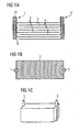
- Figure 1A shows a detail of a schematic cross section of a piezoelectric multilayer component.
- the component has superimposed electrode layers with first inner electrodes 3 and second inner electrodes 4 structured therein.
- Dielectric layers 5, preferably ceramic layers, are arranged between the electrode layers.
- the internal electrodes 3, 4 are mutually contacted with contact elements 1, 2.
- the respectively associated internal electrodes - first electrode layers 3 and second electrode layers 4 - are electrically connected to one another by means of the contact element 1 or 2 which is insulated from the respective other internal electrodes.
- the contact elements 1, 2 extend transversely to the main surfaces of the internal electrodes.
- the contact elements 1, 2 each contain a porous body 11.
- An electrically conductive layer 12 is applied to the surface or lateral surface of the porous body 11.
- FIG. 1B a patterned electrode layer is shown with a first inner electrode 3 formed therein.
- the first inner electrode 3 is connected on the left to the first contact element 1 and has a recess on the right, by which it is electrically insulated from the second contact element 2.
- the device according to Figure 1A is in a perspective view from the side in Figure 1C shown. At two opposite outer sides of the base body each extending in the axial direction recess is formed in the form of a groove.
- the porous elements having a contact elements 1, 2 are preferably preformed prior to sintering of the base body.
- the lateral surface of the porous body and / or the surface of the recess provided for this purpose is coated with an adhesion-promoting layer, for. B. covered a metal paste and put the contact element in the recess.
- the main body is then sintered together with the contact element.
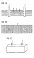
- the contact element in cross section is only partially surrounded by the body.
- the contact elements 1, 2 are each arranged in the main body, so that the contact element is surrounded in cross-section on all sides by the body.
- An opening is formed in the base body transversely to the electrode layers, into which the contact element preformed in the form of a pin is inserted.
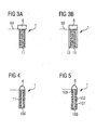
- FIGS. 3A, 3B, 4 and 5 Different variants of a contact element are shown. However, there are also other possibilities for forming a contact element comprising a porous body.
- FIG. 3A a contact element 1 with a porous body 10 is shown.
- the contact element 1 consists in this variant of a porous body.
- the porous body 10 is preferably cylindrical, but may in principle be a porous pin of any cross section.
- an electrically conductive cap 6 is slipped, which leads to a further contacting of the device z. B. with a supply line 60 is used.
- the supply line 60 is, for example, an electrical wire.
- FIG. 3B is a contact element 1 with a porous body 11 according to FIG. 3A shown, whose lateral surface is covered by an electrically conductive layer 12.
- FIG. 4 a contact element 1 with a porous body 11 is shown, in which a preferably electrically conductive pin 100 extends.
- the pin 100 is a preferably solid carrier pin which carries the porous body 11.
- FIG. 5 shows a variant of in FIG. 4 shown embodiment.
- the pin 100 a plurality of porous body 101, 102, 103 mounted at a distance from each other.
- the pin 100 is preferably, but not necessarily, made of metal. Any reasonably stable electrically conductive materials come into consideration.
- a massive pen can in FIGS. 4, 5 be replaced by a metal tube.
- the invention is not limited to the presented embodiments.
- any suitable materials may be used for the production of a porous body of the contact element as well as the dielectric layers of the main body of the device.
- the porous body of the contact element may, but need not be preformed.
- Suitable electrode layers are all metals or metal alloys which are stable under sintering conditions.
- electrode layers made of copper or of a mixture of silver and palladium in a weight ratio between 90/10 and 70/30 come into consideration.
Landscapes
- General Electrical Machinery Utilizing Piezoelectricity, Electrostriction Or Magnetostriction (AREA)
- Fuel-Injection Apparatus (AREA)
Abstract
Claims (25)
- Composant multicouche comportant au moins deux couches métalliques séparées l'une de l'autre par une couche diélectrique (5) et reliées électriquement l'une à l'autre par un élément de contact (1, 2) qui contient un corps poreux (11), l'élément de contact (1, 2) ayant la forme d'une tige.
- Composant selon la revendication 1, dans lequel la porosité du corps poreux (11) représente plus de 10 % de son volume.
- Composant selon les revendications 1 ou 2, dans lequel les couches diélectriques (5) superposées et les électrodes intérieures (3, 4) situées entre elles forment un corps de base et dans lequel l'élément de contact (1, 2) s'étend perpendiculairement aux électrodes intérieures et les met en contact.
- Composant selon l'une des revendications 1 à 3, dans lequel les couches diélectriques (5) présentent chacune des propriétés piézoélectriques.
- Composant selon l'une des revendications 1 à 4, dans lequel les couches diélectriques (5) contiennent un matériau céramique et sont frittées les unes aux autres.
- Composant selon l'une des revendications 3 à 5, présentant des premières électrodes intérieures (3) et des deuxièmes électrodes intérieures (4) superposées en succession alternée, les premières électrodes intérieures (3) étant toutes en contact avec un premier élément de contact (1) et étant isolées d'un deuxième élément de contact (2), les deuxièmes électrodes intérieures (4) étant chacune en contact avec le deuxième élément de contact (2) et étant isolées du premier élément de contact (1).
- Composant selon l'une des revendications 1 à 6, dans lequel le corps poreux (11) présente une couche électriquement conductrice (12) disposée sur le corps poreux (11).
- Composant selon la revendication 7, dans lequel la couche électriquement conductrice (12) est une pâte métallique de cuisson.
- Composant selon l'une des revendications 1 à 8, dans lequel une tige pleine (100) en matériau électriquement conducteur est disposée dans le corps poreux (11).
- Composant selon la revendication 9, dans lequel plusieurs corps poreux (101, 102, 103) disposés les uns au-dessus des autres et séparés les uns des autres par un interstice d'air sont fixés sur la tige pleine (100).
- Composant selon l'une des revendications 1 à 10, dans lequel un capuchon de contact (6) en matériau électriquement conducteur est prévu sur un côté frontal du corps poreux (11) de l'élément de contact (1, 2).
- Composant selon la revendication 11, dans lequel le matériau électriquement conducteur du capuchon de contact (6) peut être brasé.
- Composant selon l'une des revendications 3 à 12, dans lequel une découpe qui reprend l'élément de contact (1, 2) est ménagée sur un côté extérieur du corps de base.
- Composant selon l'une des revendications 3 à 12, dans lequel une ouverture de reprise de l'élément de contact (1, 2) est ménagée à l'intérieur du corps de base.
- Composant selon l'une des revendications 1 à 14, dans lequel le matériau du corps poreux (11) a une porosité ouverte.
- Composant selon l'une des revendications 1 à 15, dans lequel le matériau du corps poreux (11) est électriquement conducteur.
- Composant selon la revendication 16, dans lequel le matériau du corps de base (11) est une éponge métallique.
- Composant selon l'une des revendications 1 à 15, dans lequel le matériau du corps poreux (11) est un matériau minéral.
- Composant selon l'une des revendications 1 à 15 et 18, dans lequel le matériau du corps poreux (11) n'est pas électriquement conducteur et dans lequel la surface du corps poreux (11) est dotée d'une couche électriquement conductrice (12).
- Composant selon les revendications 18 ou 19, dans lequel le matériau du corps poreux (11) contient une céramique.
- Composant selon l'une des revendications 1 à 12 et 16, dans lequel le matériau du corps poreux (11) est un matériau minéral.
- Composant selon les revendications 18 ou 21, dans lequel la surface du corps poreux (11) est dotée d'une couche électriquement conductrice (12).
- Composant selon l'une des revendications 3 à 12 et 14 à 22, dans lequel l'élément de contact (1, 2) est disposé au centre à l'intérieur du corps de base.
- Composant selon la revendication 23, dans lequel l'élément de contact (1, 2) disposé au centre à l'intérieur du corps de base présente une tige métallique (100) et plusieurs segments (101, 102, 103) en un matériau poreux et conducteur, fixés sur la tige métallique et reliés électriquement à cette dernière.
- Composant selon l'une des revendications 1 à 24, dans lequel le corps poreux (11) de l'élément de contact (1, 2) s'étend transversalement par rapport aux couches métalliques.
Applications Claiming Priority (3)
| Application Number | Priority Date | Filing Date | Title |
|---|---|---|---|
| DE102005003693 | 2005-01-26 | ||
| DE102005017108A DE102005017108A1 (de) | 2005-01-26 | 2005-04-13 | Piezoelektrisches Bauelement |
| PCT/DE2006/000114 WO2006079324A1 (fr) | 2005-01-26 | 2006-01-25 | Composant piezoelectrique |
Publications (2)
| Publication Number | Publication Date |
|---|---|
| EP1842246A1 EP1842246A1 (fr) | 2007-10-10 |
| EP1842246B1 true EP1842246B1 (fr) | 2012-03-07 |
Family
ID=36130193
Family Applications (1)
| Application Number | Title | Priority Date | Filing Date |
|---|---|---|---|
| EP06705850A Ceased EP1842246B1 (fr) | 2005-01-26 | 2006-01-25 | Composant piezoelectrique |
Country Status (5)
| Country | Link |
|---|---|
| US (1) | US7868524B2 (fr) |
| EP (1) | EP1842246B1 (fr) |
| JP (1) | JP5408881B2 (fr) |
| DE (1) | DE102005017108A1 (fr) |
| WO (1) | WO2006079324A1 (fr) |
Families Citing this family (13)
| Publication number | Priority date | Publication date | Assignee | Title |
|---|---|---|---|---|
| DE102005017108A1 (de) | 2005-01-26 | 2006-07-27 | Epcos Ag | Piezoelektrisches Bauelement |
| DE102005026717B4 (de) * | 2005-06-09 | 2016-09-15 | Epcos Ag | Piezoelektrisches Vielschichtbauelement |
| DE102006019900A1 (de) * | 2006-04-28 | 2007-11-08 | Siemens Ag | Piezoaktor mit Gradient-Verkapselungsschicht und Verfahren zu seiner Herstellung |
| DE102008055144A1 (de) * | 2008-12-23 | 2010-07-01 | Robert Bosch Gmbh | Piezoaktor, Kraftstoff-Injetor mit Piezoaktor sowie Verfahren zum Herstellen eines Piezoaktors |
| DE102008055131A1 (de) * | 2008-12-23 | 2010-07-01 | Robert Bosch Gmbh | Piezoaktor, Kraftstoff-Injektor mit Piezoaktor sowie Verfahren zum Herstellen eines Piezoaktors |
| DE102011003680A1 (de) | 2011-02-07 | 2012-08-09 | Robert Bosch Gmbh | Verfahren zur Herstellung von piezoelektrischen Werkstücken |
| DE202011107838U1 (de) | 2011-06-28 | 2011-12-14 | Horst Ahlers | Anordnung zur Einhaltung von Diabeteszielgrößen |
| DE102012105647A1 (de) | 2012-06-27 | 2014-01-02 | Pro-Micron Gmbh & Co. Kg | Aus einer Spule und einem daran angeschlossenen Piezoelement kombiniertes elektrisches Element |
| DE102013200244A1 (de) * | 2013-01-10 | 2014-07-10 | Robert Bosch Gmbh | Piezoelektrisches Bauteil und Verfahren zur Herstellung eines piezoelektrischen Bauteils |
| DE102013108753A1 (de) | 2013-08-13 | 2015-02-19 | Epcos Ag | Vielschichtbauelement mit einer Außenkontaktierung und Verfahren zur Herstellung eines Vielschichtbauelements mit einer Außenkontaktierung |
| KR20150019586A (ko) * | 2013-08-14 | 2015-02-25 | 삼성전기주식회사 | 압전 액추에이터 모듈 및 이의 제조방법 |
| US10241500B2 (en) | 2015-08-10 | 2019-03-26 | Buerkert Werke Gmbh | Film transducer and actuator strip for a film transducer |
| US11296272B2 (en) * | 2017-07-20 | 2022-04-05 | Taiyo Yuden Co., Ltd. | Multilayer piezoelectric element, piezoelectric vibration apparatus, and electronic device |
Citations (1)
| Publication number | Priority date | Publication date | Assignee | Title |
|---|---|---|---|---|
| WO2005104256A2 (fr) * | 2004-04-26 | 2005-11-03 | Epcos Ag | Unite fonctionnelle electrique et procede pour sa production |
Family Cites Families (48)
| Publication number | Priority date | Publication date | Assignee | Title |
|---|---|---|---|---|
| SE436675B (sv) * | 1975-08-12 | 1985-01-14 | Ki Politekhnichsky I Im 50 Let | Elektrisk motor driven genom piezoelektriska krafter |
| JPS5399457A (en) * | 1977-02-09 | 1978-08-30 | Matsushita Electric Industrial Co Ltd | Solid electrolytic capacitor |
| JPS6311701Y2 (fr) * | 1980-09-17 | 1988-04-05 | ||
| JPS5849428U (ja) * | 1981-09-28 | 1983-04-04 | 東北金属工業株式会社 | 電子部品のメツシユ型リ−ド線接続機構 |
| AT384912B (de) * | 1982-04-16 | 1988-01-25 | Ki Polt I | Piezoelektrischer motor |
| AT382262B (de) * | 1982-04-16 | 1987-02-10 | Ki Polt I | Piezoelektrischer motor |
| DE3725454A1 (de) * | 1987-07-31 | 1989-02-09 | Siemens Ag | Elektrisches vielschichtbauelement mit einem gesinterten, monolithischen keramikkoerper und verfahren zur herstellung des elektrischen vielschichtbauelementes |
| JPH0576065U (ja) * | 1992-03-23 | 1993-10-15 | ティーディーケイ株式会社 | 積層型圧電体装置 |
| DE19648545B4 (de) * | 1996-11-25 | 2009-05-07 | Ceramtec Ag | Monolithischer Vielschichtaktor mit Außenelektroden |
| JPH10233537A (ja) * | 1997-02-20 | 1998-09-02 | Toyota Motor Corp | 圧電積層体 |
| JP3139452B2 (ja) * | 1998-04-10 | 2001-02-26 | 日本電気株式会社 | 圧電トランス及びその製造方法 |
| JP2000077733A (ja) * | 1998-08-27 | 2000-03-14 | Hitachi Ltd | 積層型圧電素子 |
| US20020098333A1 (en) * | 1999-12-16 | 2002-07-25 | Adalbert Feltz | Piezoceramic device |
| WO2001047318A2 (fr) * | 1999-12-21 | 2001-06-28 | 1... Limited | Haut-parleur utilisant un dispositif electro-actif |
| DE10152490A1 (de) * | 2000-11-06 | 2002-05-08 | Ceramtec Ag | Außenelektroden an piezokeramischen Vielschichtaktoren |
| DE10055241A1 (de) * | 2000-11-08 | 2002-05-29 | Epcos Ag | Piezoaktor |
| DE10109994A1 (de) * | 2001-03-01 | 2002-09-05 | Patent Treuhand Ges Fuer Elektrische Gluehlampen Mbh | Piezotransformator mit großem Übersetzungsverhältnis |
| GB0111308D0 (en) * | 2001-05-09 | 2001-06-27 | Tyco Electronics Ltd Uk | Electrical interconnect assembly |
| JP2005505187A (ja) * | 2001-09-28 | 2005-02-17 | エプコス アクチエンゲゼルシャフト | 回路装置、該回路装置を有するスイッチングモジュール、および該スイッチングモジュールの使用方法 |
| US7492565B2 (en) * | 2001-09-28 | 2009-02-17 | Epcos Ag | Bandpass filter electrostatic discharge protection device |
| US7343137B2 (en) * | 2001-09-28 | 2008-03-11 | Epcos Ag | Circuit, switching module comprising the same, and use of said switching module |
| US20050059371A1 (en) * | 2001-09-28 | 2005-03-17 | Christian Block | Circuit arrangement, switching module comprising said circuit arrangement and use of switching module |
| DE10201641A1 (de) * | 2002-01-17 | 2003-08-07 | Epcos Ag | Piezoelektrisches Bauelement und Verfahren zu dessen Herstellung |
| EP1329915A1 (fr) | 2002-01-21 | 2003-07-23 | Abb Research Ltd. | Condensateur et sa méthode de fabrication |
| EP1502310B1 (fr) | 2002-05-06 | 2008-11-12 | Epcos Ag | Piezoactionneur et son procede de production |
| DE10233400A1 (de) * | 2002-07-23 | 2004-02-12 | Patent-Treuhand-Gesellschaft für elektrische Glühlampen mbH | Schaltungsanordnung zum Betrieb von Entladungslampen |
| DE10236986A1 (de) * | 2002-08-13 | 2004-02-26 | Robert Bosch Gmbh | Piezoaktor |
| DE10249900A1 (de) * | 2002-10-25 | 2004-05-06 | Epcos Ag | Piezoelektrisches Bauelement |
| JP4211419B2 (ja) | 2003-02-05 | 2009-01-21 | 株式会社デンソー | 積層型圧電体素子 |
| JP2004319967A (ja) * | 2003-03-31 | 2004-11-11 | Denso Corp | 積層型圧電素子 |
| DE10335019A1 (de) * | 2003-07-31 | 2005-02-17 | Robert Bosch Gmbh | Piezoaktor |
| JP4480371B2 (ja) * | 2003-08-26 | 2010-06-16 | 京セラ株式会社 | 積層型圧電素子及び噴射装置 |
| WO2005029602A1 (fr) * | 2003-09-24 | 2005-03-31 | Kyocera Corporation | Dispositif piezo-electrique multicouche |
| DE10345499A1 (de) * | 2003-09-30 | 2005-04-28 | Epcos Ag | Piezoelektrisches Keramikmaterial, Vielschichtbauelement und Verfahren zur Herstellung des Keramikmaterials |
| DE10345500B4 (de) * | 2003-09-30 | 2015-02-12 | Epcos Ag | Keramisches Vielschicht-Bauelement |
| DE102004002204A1 (de) * | 2004-01-15 | 2005-08-11 | Epcos Ag | Keramikmaterial |
| DE102004038103A1 (de) * | 2004-08-05 | 2006-02-23 | Epcos Ag | Vielschichtbauelement und Verfahren zu dessen Herstellung |
| JP5090909B2 (ja) * | 2004-08-13 | 2012-12-05 | エプコス アクチエンゲゼルシャフト | 圧電トランス |
| JP2008509566A (ja) * | 2004-08-13 | 2008-03-27 | エプコス アクチエンゲゼルシャフト | 圧電(ピエゾ)トランス |
| DE102004058743A1 (de) * | 2004-12-06 | 2006-06-14 | Epcos Ag | Piezoelektrischer Transformator und Verfahren zu dessen Herstellung |
| DE102005018791A1 (de) * | 2005-01-18 | 2006-07-27 | Epcos Ag | Piezoaktor mit niedriger Streukapazität |
| DE102005017108A1 (de) | 2005-01-26 | 2006-07-27 | Epcos Ag | Piezoelektrisches Bauelement |
| DE102005026717B4 (de) * | 2005-06-09 | 2016-09-15 | Epcos Ag | Piezoelektrisches Vielschichtbauelement |
| DE102005036077A1 (de) * | 2005-08-01 | 2007-04-26 | Epcos Ag | Tranformatoranordnung mit einem Piezotransformator |
| DE102005047368A1 (de) * | 2005-10-04 | 2007-04-05 | Epcos Ag | Piezoelektrischer Transformator und Verfahren zu dessen Herstellung |
| DE102006025963A1 (de) * | 2006-06-02 | 2007-12-06 | Epcos Ag | Piezoelektrischer Generator |
| DE102006028534A1 (de) * | 2006-06-21 | 2007-12-27 | Epcos Ag | Piezoelektrischer Generator |
| EP1978567B1 (fr) * | 2007-02-19 | 2014-06-25 | Continental Automotive GmbH | Actionneur multicouche en piézocéramique et son procédé de fabrication |
-
2005
- 2005-04-13 DE DE102005017108A patent/DE102005017108A1/de not_active Withdrawn
-
2006
- 2006-01-25 JP JP2007552500A patent/JP5408881B2/ja not_active Expired - Fee Related
- 2006-01-25 EP EP06705850A patent/EP1842246B1/fr not_active Ceased
- 2006-01-25 WO PCT/DE2006/000114 patent/WO2006079324A1/fr not_active Ceased
- 2006-01-25 US US11/814,441 patent/US7868524B2/en not_active Expired - Fee Related
Patent Citations (1)
| Publication number | Priority date | Publication date | Assignee | Title |
|---|---|---|---|---|
| WO2005104256A2 (fr) * | 2004-04-26 | 2005-11-03 | Epcos Ag | Unite fonctionnelle electrique et procede pour sa production |
Also Published As
| Publication number | Publication date |
|---|---|
| US20090243441A1 (en) | 2009-10-01 |
| DE102005017108A1 (de) | 2006-07-27 |
| JP5408881B2 (ja) | 2014-02-05 |
| JP2008529288A (ja) | 2008-07-31 |
| US7868524B2 (en) | 2011-01-11 |
| WO2006079324A1 (fr) | 2006-08-03 |
| EP1842246A1 (fr) | 2007-10-10 |
Similar Documents
| Publication | Publication Date | Title |
|---|---|---|
| EP1502310B1 (fr) | Piezoactionneur et son procede de production | |
| EP2118912B1 (fr) | Composant multicouche et procédé de production d'un tel composant multicouche | |
| EP3262666B1 (fr) | Composant électrique et procédé de manufacture de ce composant | |
| EP2201585B1 (fr) | Composant électrique multicouche | |
| EP1842246B1 (fr) | Composant piezoelectrique | |
| EP2394275B1 (fr) | Composant électrique multicouche | |
| EP2057647B1 (fr) | Ensemble composant | |
| EP3189527B1 (fr) | Composant électrique, agencement de composant électrique et méthodes de leur fabrication | |
| EP2011170A1 (fr) | Piézoactionneur et son procédé de production | |
| EP2104941B1 (fr) | Composant électrique et contact extérieur d'un composant électrique | |
| DE102009046852A1 (de) | Vielschichtaktor mit Außenelektroden als metallische, poröse, dehnbare Leitschicht | |
| EP1761936B1 (fr) | Composant multicouche electrique presentant un contact a braser fiable | |
| EP2191483B1 (fr) | Composant électrique multicouche | |
| EP1741162A2 (fr) | Unite fonctionnelle electrique et procede pour sa production | |
| WO2003034446A2 (fr) | Insert ceramique cru, insert ceramique, corps cru ceramique ou ensemble de corps crus et composite ceramique stratifie produit a partir de ce dernier | |
| EP2054951B1 (fr) | Composant piézoélectrique | |
| WO2008040307A2 (fr) | Procédé de fabrication d'un agencement de composants optoélectroniques et agencement de composants optoélectroniques | |
| EP2901504B1 (fr) | Composant électrique et procédé d'établissement d'une mise en contact électrique d'un composant électrique | |
| DE10259320B4 (de) | Druckkontaktiertes elektrisches Bauelement | |
| DE102014109183A1 (de) | Verfahren zur Herstellung eines Schaltungsträgers und zum Verbinden eines elektrischen Leiters mit einer Metallisierungsschicht eines Schaltungsträgers | |
| DD283458A5 (de) | Zuendbrueckentraeger fuer elektrische zuender | |
| DE102015017344B3 (de) | Keramisches Bauelement, Bauelementanordnung und Verfahren zur Herstellung eines keramischen Bauelemements | |
| DE202021103654U1 (de) | Elektrische Komponente mit geschichteter Struktur mit verbesserter Durchschlagleistung | |
| DE102006023088A1 (de) | Leistungshalbleiterbauteil und Verfahren zu seiner Herstellung | |
| DE10130927A1 (de) | Verfahren zum Integrieren eines elektronischen Bauteils in einem keramischen Körper und derartiger keramischer Körper |
Legal Events
| Date | Code | Title | Description |
|---|---|---|---|
| PUAI | Public reference made under article 153(3) epc to a published international application that has entered the european phase |
Free format text: ORIGINAL CODE: 0009012 |
|
| 17P | Request for examination filed |
Effective date: 20070518 |
|
| AK | Designated contracting states |
Kind code of ref document: A1 Designated state(s): DE FR GB |
|
| RBV | Designated contracting states (corrected) |
Designated state(s): DE FR GB |
|
| DAX | Request for extension of the european patent (deleted) | ||
| 17Q | First examination report despatched |
Effective date: 20090917 |
|
| GRAP | Despatch of communication of intention to grant a patent |
Free format text: ORIGINAL CODE: EPIDOSNIGR1 |
|
| GRAS | Grant fee paid |
Free format text: ORIGINAL CODE: EPIDOSNIGR3 |
|
| GRAA | (expected) grant |
Free format text: ORIGINAL CODE: 0009210 |
|
| AK | Designated contracting states |
Kind code of ref document: B1 Designated state(s): DE FR GB |
|
| REG | Reference to a national code |
Ref country code: GB Ref legal event code: FG4D Free format text: NOT ENGLISH |
|
| REG | Reference to a national code |
Ref country code: DE Ref legal event code: R096 Ref document number: 502006011080 Country of ref document: DE Effective date: 20120503 |
|
| PLBE | No opposition filed within time limit |
Free format text: ORIGINAL CODE: 0009261 |
|
| STAA | Information on the status of an ep patent application or granted ep patent |
Free format text: STATUS: NO OPPOSITION FILED WITHIN TIME LIMIT |
|
| 26N | No opposition filed |
Effective date: 20121210 |
|
| REG | Reference to a national code |
Ref country code: DE Ref legal event code: R097 Ref document number: 502006011080 Country of ref document: DE Effective date: 20121210 |
|
| GBPC | Gb: european patent ceased through non-payment of renewal fee |
Effective date: 20130125 |
|
| PG25 | Lapsed in a contracting state [announced via postgrant information from national office to epo] |
Ref country code: GB Free format text: LAPSE BECAUSE OF NON-PAYMENT OF DUE FEES Effective date: 20130125 |
|
| REG | Reference to a national code |
Ref country code: FR Ref legal event code: PLFP Year of fee payment: 11 |
|
| REG | Reference to a national code |
Ref country code: FR Ref legal event code: PLFP Year of fee payment: 12 |
|
| REG | Reference to a national code |
Ref country code: FR Ref legal event code: PLFP Year of fee payment: 13 |
|
| REG | Reference to a national code |
Ref country code: DE Ref legal event code: R082 Ref document number: 502006011080 Country of ref document: DE Representative=s name: EPPING HERMANN FISCHER PATENTANWALTSGESELLSCHA, DE Ref country code: DE Ref legal event code: R081 Ref document number: 502006011080 Country of ref document: DE Owner name: TDK ELECTRONICS AG, DE Free format text: FORMER OWNER: EPCOS AG, 81669 MUENCHEN, DE |
|
| PGFP | Annual fee paid to national office [announced via postgrant information from national office to epo] |
Ref country code: FR Payment date: 20190122 Year of fee payment: 14 Ref country code: DE Payment date: 20190129 Year of fee payment: 14 |
|
| REG | Reference to a national code |
Ref country code: DE Ref legal event code: R119 Ref document number: 502006011080 Country of ref document: DE |
|
| PG25 | Lapsed in a contracting state [announced via postgrant information from national office to epo] |
Ref country code: FR Free format text: LAPSE BECAUSE OF NON-PAYMENT OF DUE FEES Effective date: 20200131 Ref country code: DE Free format text: LAPSE BECAUSE OF NON-PAYMENT OF DUE FEES Effective date: 20200801 |