EP1842323B1 - Doppelmodus-erkennung einer mit strom versorgten vorrichtung in einem power-over-ethernet-system - Google Patents
Doppelmodus-erkennung einer mit strom versorgten vorrichtung in einem power-over-ethernet-system Download PDFInfo
- Publication number
- EP1842323B1 EP1842323B1 EP06717528.1A EP06717528A EP1842323B1 EP 1842323 B1 EP1842323 B1 EP 1842323B1 EP 06717528 A EP06717528 A EP 06717528A EP 1842323 B1 EP1842323 B1 EP 1842323B1
- Authority
- EP
- European Patent Office
- Prior art keywords
- force
- detection
- voltage
- mode
- current
- Prior art date
- Legal status (The legal status is an assumption and is not a legal conclusion. Google has not performed a legal analysis and makes no representation as to the accuracy of the status listed.)
- Expired - Lifetime
Links
Images


Classifications
-
- H—ELECTRICITY
- H04—ELECTRIC COMMUNICATION TECHNIQUE
- H04B—TRANSMISSION
- H04B3/00—Line transmission systems
- H04B3/02—Details
- H04B3/44—Arrangements for feeding power to a repeater along the transmission line
-
- H—ELECTRICITY
- H04—ELECTRIC COMMUNICATION TECHNIQUE
- H04L—TRANSMISSION OF DIGITAL INFORMATION, e.g. TELEGRAPHIC COMMUNICATION
- H04L49/00—Packet switching elements
- H04L49/35—Switches specially adapted for specific applications
- H04L49/351—Switches specially adapted for specific applications for local area network [LAN], e.g. Ethernet switches
-
- H—ELECTRICITY
- H04—ELECTRIC COMMUNICATION TECHNIQUE
- H04L—TRANSMISSION OF DIGITAL INFORMATION, e.g. TELEGRAPHIC COMMUNICATION
- H04L12/00—Data switching networks
- H04L12/02—Details
- H04L12/10—Current supply arrangements
-
- H—ELECTRICITY
- H04—ELECTRIC COMMUNICATION TECHNIQUE
- H04L—TRANSMISSION OF DIGITAL INFORMATION, e.g. TELEGRAPHIC COMMUNICATION
- H04L12/00—Data switching networks
- H04L12/28—Data switching networks characterised by path configuration, e.g. LAN [Local Area Networks] or WAN [Wide Area Networks]
-
- H—ELECTRICITY
- H02—GENERATION; CONVERSION OR DISTRIBUTION OF ELECTRIC POWER
- H02H—EMERGENCY PROTECTIVE CIRCUIT ARRANGEMENTS
- H02H3/00—Emergency protective circuit arrangements for automatic disconnection directly responsive to an undesired change from normal electric working condition with or without subsequent reconnection ; integrated protection
- H02H3/12—Emergency protective circuit arrangements for automatic disconnection directly responsive to an undesired change from normal electric working condition with or without subsequent reconnection ; integrated protection responsive to underload or no-load
Definitions
- This disclosure relates to power supply systems, and more particularly, to circuitry and methodology for detection of a Powered Device (PD) in a Power over Ethernet (PoE) system.
- PD Powered Device
- PoE Power over Ethernet
- Ethernet has become the most commonly used method for local area networking.
- IEEE 802.3 group the originator of the Ethernet standard, has developed an extension to the standard, known as IEEE 802.3af, that defines supplying power over Ethernet cabling.
- IEEE 802.3af defines a Power over Ethernet (PoE) system that involves delivering power over unshielded twisted-pair wiring from Power Sourcing Equipment (PSE) to a Powered Device (PD) located at opposite sides of a link.
- PSE Power Sourcing Equipment
- PD Powered Device
- network devices such as IP phones, wireless LAN access points, personal computers and Web cameras, have required two connections: one to a LAN and another to a power supply system.
- the PoE system eliminates the need for additional outlets and wiring to supply power to network devices. Instead, power is supplied over Ethernet cabling used for data transmission.
- PSE and PD are non-data entities allowing network devices to supply and draw power using the same generic cabling as is used for data transmission.
- a PSE is the equipment electrically specified at the point of the physical connection to the cabling, that provides the power to a link.
- a PSE is typically associated with an Ethernet switch, router, hub or other network switching equipment or midspan device.
- a PD is a device that is either drawing power or requesting power. PDs may be associated with such devices as digital IP telephones, wireless network access points, PDA or notebook computer docking stations, cell phone chargers and HVAC thermostats.
- PSE's main functions are to search the link for a PD requesting power, optionally classify the PD, supply power to the link if a PD is detected, monitor the power on the link, and disconnect power when it is no longer requested or required.
- a PD participates in the PD detection procedure by presenting detection signature to request power.
- the PD detection signature has electrical characteristics measured by the PSE.
- the PSE may probe its port with two voltages in the range from 2.8V to 10V with at least a 1V voltage difference to determine a signature resistance of the PD.
- the signature resistance in the range from 19KOhm to 26.5KOhm is considered to be a valid detection signature.
- EP 1 221 783 A1 relates to a remote power feed device for supplying a remote power feed to a terminal in a telecommunication netwok which includes a first resistor and a second resistor in parallel with the first resistor. It compares the voltage at the terminal of the first resistor with a first threshold voltage and the voltage at the terminals of the second resistor with a second threshold voltage.
- the PSE can erroneously consider a non-PoE device to be a PD. The PSE may then attempt to power this device causing damage if the device cannot tolerate the applied power.
- the present disclosure offers novel circuitry and methodology for detecting a Powered Device (PD) in a system for providing power to the PD that includes PD detection circuitry for detecting the PD in a first mode by providing detection current to probe the PD, and for detecting the PD in a second mode by providing detection voltage to probe the PD.
- a control circuit determines that the PD is a valid device if the PD is detected both in the first mode and in the second mode.
- the PD detection circuitry may comprise a force-current detection circuit for operating in the first mode and the force-voltage detection circuit for operating in the second mode.
- a Power Sourcing Equipment (PSE) in a Power over Ethernet (PoE) system may comprise a PD detection source for detecting a PD in a force-current mode and in a force-voltage mode, and a control circuit for validating the PD if the PD is detected in both the force-current mode and the force-voltage mode.
- PSE Power Sourcing Equipment
- PoE Power over Ethernet
- the PD detection source may comprise a force-current detection circuit for producing detection current to probe the PD in the force-current mode, and the force-voltage detection circuit for producing detection voltage to probe the PD in the force-voltage mode.
- the control circuit may control the force-current detection circuit to determine the signature resistance in the force-current mode, and may control the force-voltage detection circuit to determine the signature resistance in the force-voltage mode
- the prescribed parameter of the PD may include prescribed resistance in the PD.
- the force-voltage mode may be carried out by probing the PD with test voltage of a prescribed value.
- the force-current mode may be carried out by probing the PD with test current corresponding to the test voltage of the prescribed value.
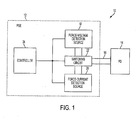
- FIG. 1 shows a simplified block-diagram of a PD detection system 10 of the present disclosure in a PoE system comprising a PSE 12, and a PD 14 connectable to the PSE 12 via a link 16, such as a 2-wire link defined in the IEEE 802.3af standard.
- the PD detection system 10 includes a force-voltage detection source 18, a force-current detection source 20, a switching circuit 22 and a controller 24 that may be arranged in the PSE 12.
- the force-current detection source 20 produces detection current Idet that corresponds to detection voltage Vdet in a pre-defined valid voltage range.
- the valid Vdet voltage range may be from 2.8V to 10V, as specified in the IEEE 802.3af standard.
- the source resistance Rsc may be in the range from 100KOhm to 100MOhm.
- the minimum current difference between values of the detection current Idet produced for different detection tests corresponds to a Vdet voltage difference of 1V.
- FIG. 4 is a flow chart illustrating a control algorithm carried out by the controller 24 to control the PD detection system 10.
- the controller 24 may be a state machine or a microcontroller arranged in the PSE 12. After a PD detection procedure is initiated (step 102), the controller 24 may switch the PD detection system 10 into a force-current mode. In this mode, the controller 24 controls the force-current detection source 20 to apply detection current I 1 to the PD 14 and measure voltage V 1 produced in response to the detection current I 1 (step 104). Thereafter, the controller 24 commands the force-current detection source 20 to apply detection current I 2 to the PD 14 and measure voltage V 2 produced in response to the detection current I 2 (step 106).
- the controller 24 determines that the signature resistance Rsig is valid, it still cannot make a conclusion as to whether the PD 14 is a device compliant with the IEEE 802.3af standard. For example, if the signature resistance of the PD 14 or PoE line changes during the measurement of response voltages, or if the PD 14 has a non-linear resistance in the range of detection values, the controller 24 can erroneously consider the PD 14 to be a device compliant with the IEEE 802.3af standard. The PSE 12 may then attempt to power this device causing damage if the device cannot tolerate the applied power.
- the controller 24 switches the PD detection system 10 in a force-voltage mode of operation to further validate the detected PD.
- the PD detection procedure of the present disclosure begins with the force-current detection mode because this mode enables the PD detection system 10 to better reject noise associated with the PoE line, to provide more accurate signature resistance determination. Hence, a non-compliant PD may be rejected after performing detection in the initial detection mode.
- the force-voltage detection mode may be carried out before the force-current detection mode.
- the controller 24 controls the force-voltage detection source 18 to apply detection voltage V 3 to the PD 14 and measure current I 3 produced in response to the detection voltage V 3 (step 114). Thereafter, the controller 24 controls the force-voltage detection source 18 to apply detection voltage V 4 to the PD 14 and measure current I 4 produced in response to the detection voltage V 4 (step 116).
- the pre-defined range for the signature resistance in the force-voltage mode may coincide with this range in the force-current mode.
- the controller 24 concludes that the PD 24 is not a PD compliant with the IEEE 802.3af standard and terminates the detection procedure (step 112). However, if the signature resistance Rsig is within the pre-defined range, the PD 14 is validated (step 120).
- further PD detection procedures may be carried out in the force-current detection mode and/or in the force-voltage detection mode to further reduce likelihood of a false detection.
- the PSE 12 may perform a classification procedure to determine a class of the PD 14 and provide the PD 14 with requested amount of power.
Landscapes
- Engineering & Computer Science (AREA)
- Computer Networks & Wireless Communication (AREA)
- Signal Processing (AREA)
- Small-Scale Networks (AREA)
- Communication Control (AREA)
- Cable Transmission Systems, Equalization Of Radio And Reduction Of Echo (AREA)
- Power Sources (AREA)
Claims (20)
- Ein System zur Stromversorgung eines Powered Devices, PDs, (14), das Folgendes umfasst:eine PD-Erfassungsschaltung, zur Erfassung des PDs (14) in einem Erzwungenen-Strom-Modus (force current mode), indem man einen Erfassungsstrom zur Prüfung des PDs (14) bereitstellt, und in einem Erzwungenen-Spannungs-Modus (force voltage mode), indem man eine Erfassungsspannung, zur Prüfung des PDs (14) bereitstellt, undeine Steuerungsschaltung (24), um zu bestimmen, dass der PD (14) ein gültiges Gerät ist, falls der PD (14) sowohl im Erzwungenen-Strom-Modus, als auch im Erzwungenen-Spannungs-Modus erkannt wird.
- Das System nach Anspruch 1, wobei die PD-Erfassungsschaltung dazu konfiguriert ist, eine Spannung zu erfassen, die als Antwort auf den Erfassungsstrom im Erzwungenen-Strom-Modus erzeugt wird, und um einen Strom zu erfassen, die als Antwort auf die Erfassungsspannung im Erzwungenen-Spannungs-Modus erzeugt wird.
- Das System nach Anspruch 1, wobei die PD-Erfassungsschaltung eine Erzwungener-Strom-Erfassungsschaltung (20) umfasst, um im ersten Erzwungenen-Strom-Modus zu funktionieren und eine Erzwungene-Spannungs-Erfassungsschaltung (18), um im Erzwungenen-Spannungs-Modus zu funktionieren.
- Das System nach Anspruch 1, wobei die PD-Erfassungsschaltung dazu konfiguriert ist, einen vorgeschriebenen Widerstand im PD (14) im Erzwungenen-Strom-Modus und im Erzwungenen-Spannungs-Modus zu erfassen.
- Das System nach Anspruch 1, wobei die PD-Erfassungsschaltung dazu konfiguriert ist, den PD (14) sequenziell im Erzwungenen-Strom-Modus und im Erzwungenen-Spannungs-Modus zu erfassen.
- Das System nach Anspruch 5, wobei die PD-Erfassungsschaltung dazu gesteuert wird, um den PD (14) im Erzwungenen-Strom-Modus zu erfassen, bevor der PD (14) im Erzwungenen-Spannungs-Modus erfasst wird.
- Das System nach Anspruch 1, wobei die Steuerungsschaltung (24) dazu konfiguriert ist, die PD-Erfassungsschaltung so zu steuern, dass sie im Erzwungenen-Strom-Modus und im Erzwungenen-Spannungs-Modus funktioniert.
- Ein Power Sourcing Equipment (PSE) in einem Power over Ethernet (PoE) System, das Folgendes umfasst:eine PD-Erfassungsquelle, zur Erfassung eines PDs (14) in einem Erzwungenen-Strom-Modus (force current mode) und in einem Erzwungenen-Spannungs-Modus (force voltage mode), undeine Steuerungsschaltung (24), zur Validierung des PDs (14), falls der PD (14) sowohl im Erzwungenen-Strom-Modus, als auch im Erzwungenen-Spannungs-Modus erkannt wird.
- Das PSE nach Anspruch 8, wobei die PD-Erfassungsquelle eine Erzwungener-Strom-Erfassungsschaltung (20) umfasst, zur Erzeugung eines Feststellungsstroms, um den PD (14) im Erzwungenen-Strom-Modus zu testen, und die Erzwungene-Spannungs-Erfassungsschaltung (18), zur Erzeugung einer Feststellungsspannung, um den PD (14) im Erzwungenen-Spannungs-Modus zu testen.
- Das PSE nach Anspruch 9, wobei die Erzwungener-Strom-Erfassungsschaltung (20) dazu konfiguriert ist, die Spannung zu bestimmen, die als Antwort auf den Erfassungsstrom erzeugt wird, und die Erzwungene-Spannungs-Erfassungsschaltung (18) dazu konfiguriert ist, den Strom zu bestimmen, der als Antwort auf die Erfassungsspannung erzeugt wird.
- Das PSE nach Anspruch 8, wobei die PD-Erfassungsquelle dazu konfiguriert ist, den Signatur-Widerstand im Erzwungenen-Strom-Modus und im Erzwungenen-Spannungs-Modus zu bestimmen.
- Das PSE nach Anspruch 8, wobei die PD-Erfassungsquelle dazu konfiguriert ist, den PD (14) sequenziell im Erzwungenen-Strom-Modus und im Erzwungenen-Spannungs-Modus zu erfassen.
- Das PSE nach Anspruch 8, wobei die PD-Erfassungsquelle dazu konfiguriert ist, den PD (14) im Erzwungenen-Strom-Modus zu erfassen, bevor der PD(14) im Erzwungenen-Spannungs-Modus erfasst wird.
- Das PSE nach Anspruch 8, wobei die Steuerungsschaltung (24) dazu konfiguriert ist, die PD-Erfassungsquelle so zu steuern, dass sie im Erzwungenen-Strom-Modus und im Erzwungenen-Spannungs-Modus funktioniert.
- Ein Verfahren zur Erfassung eines PDs (14), das die folgenden Schritte umfasst:bestimmen eines vorbestimmten Parameters des PDs (14) in einem Erzwungenen-Strom-Modus,bestimmen des vorbestimmten Parameters des PDs (14) in einem Erzwungenen-Spannungs-Modus, undvalidieren des PDs (14), falls der vorbestimmte Parameter des PDs (14) sowohl im Erzwungenen-Strom-Modus, als auch im Erzwungenen-Spannungs-Modus für gültig befunden worden ist.
- Das Verfahren nach Anspruch 15, wobei der vorbestimmte Parameter des PDs (14) einen vorbestimmten Widerstand im PD (14) beinhaltet.
- Das Verfahren nach Anspruch 15, wobei der Erzwungene-Strom-Modus und der Erzwungene-Spannungs-Modus sequenziell ausgeführt werden.
- Das Verfahren nach Anspruch 15, wobei der Erzwungene-Strom-Modus vor dem Erzwungenen-Spannungs-Modus ausgeführt wird.
- Das Verfahren nach Anspruch 15, wobei der Erzwungene-Spannungs-Modus ausgeführt wird, indem der PD (14) durch eine Test-Spannung geprüft wird, die einen vorgeschriebenen Wert aufweist.
- Das Verfahren nach Anspruch 19, wobei der Erzwungene-Strom-Modus ausgeführt wird, indem der PD (14) durch einen Test-Strom geprüft wird, der der Test-Spannung mit dem vorgeschriebenen Wert entspricht.
Applications Claiming Priority (3)
| Application Number | Priority Date | Filing Date | Title |
|---|---|---|---|
| US64650905P | 2005-01-25 | 2005-01-25 | |
| US11/252,624 US7613936B2 (en) | 2005-01-25 | 2005-10-19 | Dual-mode detection of powered device in power over ethernet system |
| PCT/US2006/000343 WO2006081046A2 (en) | 2005-01-25 | 2006-01-09 | Dual-mode detection of powered device in power over ethernet system |
Publications (2)
| Publication Number | Publication Date |
|---|---|
| EP1842323A2 EP1842323A2 (de) | 2007-10-10 |
| EP1842323B1 true EP1842323B1 (de) | 2015-03-18 |
Family
ID=36696514
Family Applications (1)
| Application Number | Title | Priority Date | Filing Date |
|---|---|---|---|
| EP06717528.1A Expired - Lifetime EP1842323B1 (de) | 2005-01-25 | 2006-01-09 | Doppelmodus-erkennung einer mit strom versorgten vorrichtung in einem power-over-ethernet-system |
Country Status (5)
| Country | Link |
|---|---|
| US (1) | US7613936B2 (de) |
| EP (1) | EP1842323B1 (de) |
| JP (1) | JP4598084B2 (de) |
| KR (1) | KR101214773B1 (de) |
| WO (1) | WO2006081046A2 (de) |
Families Citing this family (17)
| Publication number | Priority date | Publication date | Assignee | Title |
|---|---|---|---|---|
| CN101371492B (zh) * | 2006-01-17 | 2012-08-15 | 美国博通公司 | 以太网供电控制器及对供电设备检测和分级的方法 |
| US7774628B2 (en) * | 2006-05-25 | 2010-08-10 | Foundry Networks, Inc. | Enabling/disabling power-over-ethernet software subsystem in response to power supply status |
| US7631201B2 (en) | 2006-05-25 | 2009-12-08 | Foundry Networks, Inc. | System software for managing power allocation to Ethernet ports in the absence of mutually exclusive detection and powering cycles in hardware |
| EP1903653B1 (de) * | 2006-08-31 | 2018-09-26 | Avago Technologies General IP (Singapore) Pte. Ltd. | Überspannungsschutz für Strom- und Datenanwendungen |
| US7557549B2 (en) * | 2006-11-21 | 2009-07-07 | Honeywell International Inc. | Automatic output mode select for an actuator controller |
| US8250381B2 (en) | 2007-03-30 | 2012-08-21 | Brocade Communications Systems, Inc. | Managing power allocation to ethernet ports in the absence of mutually exclusive detection and powering cycles in hardware |
| WO2008136028A1 (en) | 2007-05-08 | 2008-11-13 | Stmicroelectronics S.R.L. | Method of discrimination of a device as powerable through a lan line and device for estimating electric parameters of a lan line |
| US8301922B2 (en) * | 2009-07-31 | 2012-10-30 | Broadcom Corporation | System and method for policing bad powered devices in power over ethernet |
| AU2010326847A1 (en) * | 2009-12-04 | 2012-06-21 | Osram Ag | A method for controlling the operation of an electronic converter, and a corresponding electronic converter, lighting system and software product |
| CN102714597B (zh) * | 2010-01-31 | 2015-11-25 | 惠普发展公司,有限责任合伙企业 | 用于减轻错误受电设备检测的方法 |
| US20110219244A1 (en) * | 2010-03-05 | 2011-09-08 | Hsi-Mien Wu | Power extracting system and a splitter |
| BR112013004654A2 (pt) | 2010-09-02 | 2016-08-02 | Koninkl Philips Electronics Nv | aparelho, método e programa de computador para fornecer energia para comsumidores de eletricidade em rede por meio de conexão de dados e sistema |
| TWI432740B (zh) | 2012-03-30 | 2014-04-01 | Wistron Corp | 網路供電裝置測試板、測試系統與測試方法 |
| US9334063B2 (en) * | 2012-09-10 | 2016-05-10 | Rosemount Aerospace, Inc. | Aircraft avionics tablet interface module |
| US9859951B2 (en) * | 2013-11-26 | 2018-01-02 | Linear Technology Corporation | Power over data lines detection and classification scheme |
| TWI584611B (zh) * | 2015-11-24 | 2017-05-21 | 九暘電子股份有限公司 | 乙太網路供電系統的受電裝置檢測裝置及方法 |
| CN113595745B (zh) * | 2016-10-13 | 2025-03-25 | 华为技术有限公司 | 供电设备、以太网供电方法与装置 |
Family Cites Families (14)
| Publication number | Priority date | Publication date | Assignee | Title |
|---|---|---|---|---|
| JPH07301646A (ja) * | 1994-05-02 | 1995-11-14 | Matsushita Electric Ind Co Ltd | プリント基板検査装置 |
| JP3383590B2 (ja) * | 1998-08-19 | 2003-03-04 | 沖電気工業株式会社 | Lan対応電話端末への給電システム |
| US6473608B1 (en) * | 1999-01-12 | 2002-10-29 | Powerdsine Ltd. | Structure cabling system |
| US6571181B1 (en) * | 1999-08-11 | 2003-05-27 | Broadcom Corporation | System and method for detecting a device requiring power |
| FR2815215B1 (fr) * | 2000-10-05 | 2003-01-31 | Cit Alcatel | Terminal apte a etre alimente localement et a etre telealimente par une liaison le reliant a un reseau local |
| FR2819364B1 (fr) * | 2001-01-08 | 2003-04-11 | Cit Alcatel | Dispositif de telealementation d'uin terminal dans un reseau de telecommunication, concentrateur, et repeteur comportant un tel dispositif |
| US6459275B1 (en) * | 2001-02-28 | 2002-10-01 | Avaya Technology Corp. | Detection of devices on a local area network |
| JP2002290490A (ja) * | 2001-03-28 | 2002-10-04 | Sony Corp | 電子機器 |
| TW200501551A (en) * | 2003-04-23 | 2005-01-01 | Rohm Co Ltd | Audio signal amplifier circuit and electronic apparatus having the same |
| US7849343B2 (en) * | 2003-06-10 | 2010-12-07 | Microsemi Corp. - Analog Mixed Signal Group Ltd. | Pre-detection of powered devices |
| US7356588B2 (en) * | 2003-12-16 | 2008-04-08 | Linear Technology Corporation | Circuits and methods for detecting the presence of a powered device in a powered network |
| US8074084B2 (en) * | 2004-11-03 | 2011-12-06 | Cisco Technology, Inc. | Powered device classification in a wired data telecommunications network |
| US7248097B2 (en) * | 2004-09-02 | 2007-07-24 | Micrel, Inc. | Voltage-activated, constant current sink circuit |
| US7599485B2 (en) * | 2005-06-24 | 2009-10-06 | Cisco Technology, Inc. | Communications system employing single-pair identity circuit for remotely powered device |
-
2005
- 2005-10-19 US US11/252,624 patent/US7613936B2/en active Active
-
2006
- 2006-01-09 EP EP06717528.1A patent/EP1842323B1/de not_active Expired - Lifetime
- 2006-01-09 WO PCT/US2006/000343 patent/WO2006081046A2/en not_active Ceased
- 2006-01-09 JP JP2007552156A patent/JP4598084B2/ja not_active Expired - Lifetime
- 2006-01-09 KR KR1020077019059A patent/KR101214773B1/ko not_active Expired - Lifetime
Non-Patent Citations (1)
| Title |
|---|
| "Amendment: Data Terminal Equipment (DTE) Power via Media Media Dependent Interface (MDI) ; D4_01Diff_1_18", IEEE DRAFT; D4_01DIFF_1_18, IEEE-SA, PISCATAWAY, NJ USA, vol. 802.3af, 19 January 2003 (2003-01-19), pages 1 - 148, XP068013786 * |
Also Published As
| Publication number | Publication date |
|---|---|
| US7613936B2 (en) | 2009-11-03 |
| JP2008529352A (ja) | 2008-07-31 |
| EP1842323A2 (de) | 2007-10-10 |
| JP4598084B2 (ja) | 2010-12-15 |
| KR20070101338A (ko) | 2007-10-16 |
| KR101214773B1 (ko) | 2012-12-21 |
| WO2006081046A3 (en) | 2006-12-14 |
| US20060164775A1 (en) | 2006-07-27 |
| WO2006081046A2 (en) | 2006-08-03 |
Similar Documents
| Publication | Publication Date | Title |
|---|---|---|
| CN101124775B (zh) | 以太网供电系统中用电设备的双模检测 | |
| EP1842324B1 (de) | Erkennung eines bestehenden strombetriebenen geräts in einem power-over-ethernet-system | |
| US7230412B2 (en) | Distinguishing network interface card from short circuit condition in power over ethernet system | |
| EP1842323B1 (de) | Doppelmodus-erkennung einer mit strom versorgten vorrichtung in einem power-over-ethernet-system | |
| KR101224712B1 (ko) | 통신 케이블의 저항치를 결정하는 장치를 구비한 통신케이블을 통해 전력을 제공하는 시스템 | |
| US20060212724A1 (en) | System and method for supporting operations of advanced power over ethernet system | |
| US20060168459A1 (en) | Providing data communication between power supply device and powered device in system for supplying power over communication link | |
| US20060164098A1 (en) | Utilization of power delivered to powered device during detection and classification mode | |
| CN104135375B (zh) | 通过通信链路供电的系统中高端和低端电流感测的组合 | |
| EP1842321B1 (de) | Stromquellenvorrichtung mit automatischer nullschaltung zur bestimmung und steuerung eines ausgangsstroms | |
| JP2008521342A (ja) | パワー・オーバ・イーサネット(登録商標)システムのためのコモンモードのデータ伝送 |
Legal Events
| Date | Code | Title | Description |
|---|---|---|---|
| PUAI | Public reference made under article 153(3) epc to a published international application that has entered the european phase |
Free format text: ORIGINAL CODE: 0009012 |
|
| 17P | Request for examination filed |
Effective date: 20070725 |
|
| AK | Designated contracting states |
Kind code of ref document: A2 Designated state(s): AT BE BG CH CY CZ DE DK EE ES FI FR GB GR HU IE IS IT LI LT LU LV MC NL PL PT RO SE SI SK TR |
|
| DAX | Request for extension of the european patent (deleted) | ||
| 17Q | First examination report despatched |
Effective date: 20090626 |
|
| RAP1 | Party data changed (applicant data changed or rights of an application transferred) |
Owner name: LINEAR TECHNOLOGY CORPORATION |
|
| REG | Reference to a national code |
Ref country code: DE Ref legal event code: R079 Ref document number: 602006044819 Country of ref document: DE Free format text: PREVIOUS MAIN CLASS: H04L0012100000 Ipc: H02H0003120000 |
|
| GRAP | Despatch of communication of intention to grant a patent |
Free format text: ORIGINAL CODE: EPIDOSNIGR1 |
|
| RIC1 | Information provided on ipc code assigned before grant |
Ipc: H04L 12/10 20060101ALI20141021BHEP Ipc: H04L 12/931 20130101ALI20141021BHEP Ipc: H02H 3/12 20060101AFI20141021BHEP |
|
| INTG | Intention to grant announced |
Effective date: 20141113 |
|
| GRAS | Grant fee paid |
Free format text: ORIGINAL CODE: EPIDOSNIGR3 |
|
| GRAA | (expected) grant |
Free format text: ORIGINAL CODE: 0009210 |
|
| AK | Designated contracting states |
Kind code of ref document: B1 Designated state(s): AT BE BG CH CY CZ DE DK EE ES FI FR GB GR HU IE IS IT LI LT LU LV MC NL PL PT RO SE SI SK TR |
|
| REG | Reference to a national code |
Ref country code: GB Ref legal event code: FG4D |
|
| REG | Reference to a national code |
Ref country code: CH Ref legal event code: EP |
|
| REG | Reference to a national code |
Ref country code: IE Ref legal event code: FG4D |
|
| REG | Reference to a national code |
Ref country code: AT Ref legal event code: REF Ref document number: 717110 Country of ref document: AT Kind code of ref document: T Effective date: 20150415 |
|
| REG | Reference to a national code |
Ref country code: DE Ref legal event code: R096 Ref document number: 602006044819 Country of ref document: DE Effective date: 20150423 |
|
| REG | Reference to a national code |
Ref country code: NL Ref legal event code: T3 |
|
| PG25 | Lapsed in a contracting state [announced via postgrant information from national office to epo] |
Ref country code: FI Free format text: LAPSE BECAUSE OF FAILURE TO SUBMIT A TRANSLATION OF THE DESCRIPTION OR TO PAY THE FEE WITHIN THE PRESCRIBED TIME-LIMIT Effective date: 20150318 Ref country code: SE Free format text: LAPSE BECAUSE OF FAILURE TO SUBMIT A TRANSLATION OF THE DESCRIPTION OR TO PAY THE FEE WITHIN THE PRESCRIBED TIME-LIMIT Effective date: 20150318 Ref country code: LT Free format text: LAPSE BECAUSE OF FAILURE TO SUBMIT A TRANSLATION OF THE DESCRIPTION OR TO PAY THE FEE WITHIN THE PRESCRIBED TIME-LIMIT Effective date: 20150318 |
|
| REG | Reference to a national code |
Ref country code: AT Ref legal event code: MK05 Ref document number: 717110 Country of ref document: AT Kind code of ref document: T Effective date: 20150318 |
|
| REG | Reference to a national code |
Ref country code: LT Ref legal event code: MG4D |
|
| PG25 | Lapsed in a contracting state [announced via postgrant information from national office to epo] |
Ref country code: GR Free format text: LAPSE BECAUSE OF FAILURE TO SUBMIT A TRANSLATION OF THE DESCRIPTION OR TO PAY THE FEE WITHIN THE PRESCRIBED TIME-LIMIT Effective date: 20150619 Ref country code: LV Free format text: LAPSE BECAUSE OF FAILURE TO SUBMIT A TRANSLATION OF THE DESCRIPTION OR TO PAY THE FEE WITHIN THE PRESCRIBED TIME-LIMIT Effective date: 20150318 |
|
| PG25 | Lapsed in a contracting state [announced via postgrant information from national office to epo] |
Ref country code: CZ Free format text: LAPSE BECAUSE OF FAILURE TO SUBMIT A TRANSLATION OF THE DESCRIPTION OR TO PAY THE FEE WITHIN THE PRESCRIBED TIME-LIMIT Effective date: 20150318 Ref country code: PT Free format text: LAPSE BECAUSE OF FAILURE TO SUBMIT A TRANSLATION OF THE DESCRIPTION OR TO PAY THE FEE WITHIN THE PRESCRIBED TIME-LIMIT Effective date: 20150720 Ref country code: RO Free format text: LAPSE BECAUSE OF FAILURE TO SUBMIT A TRANSLATION OF THE DESCRIPTION OR TO PAY THE FEE WITHIN THE PRESCRIBED TIME-LIMIT Effective date: 20150318 Ref country code: SK Free format text: LAPSE BECAUSE OF FAILURE TO SUBMIT A TRANSLATION OF THE DESCRIPTION OR TO PAY THE FEE WITHIN THE PRESCRIBED TIME-LIMIT Effective date: 20150318 Ref country code: ES Free format text: LAPSE BECAUSE OF FAILURE TO SUBMIT A TRANSLATION OF THE DESCRIPTION OR TO PAY THE FEE WITHIN THE PRESCRIBED TIME-LIMIT Effective date: 20150318 Ref country code: EE Free format text: LAPSE BECAUSE OF FAILURE TO SUBMIT A TRANSLATION OF THE DESCRIPTION OR TO PAY THE FEE WITHIN THE PRESCRIBED TIME-LIMIT Effective date: 20150318 |
|
| PG25 | Lapsed in a contracting state [announced via postgrant information from national office to epo] |
Ref country code: IS Free format text: LAPSE BECAUSE OF FAILURE TO SUBMIT A TRANSLATION OF THE DESCRIPTION OR TO PAY THE FEE WITHIN THE PRESCRIBED TIME-LIMIT Effective date: 20150718 Ref country code: AT Free format text: LAPSE BECAUSE OF FAILURE TO SUBMIT A TRANSLATION OF THE DESCRIPTION OR TO PAY THE FEE WITHIN THE PRESCRIBED TIME-LIMIT Effective date: 20150318 Ref country code: PL Free format text: LAPSE BECAUSE OF FAILURE TO SUBMIT A TRANSLATION OF THE DESCRIPTION OR TO PAY THE FEE WITHIN THE PRESCRIBED TIME-LIMIT Effective date: 20150318 |
|
| REG | Reference to a national code |
Ref country code: DE Ref legal event code: R097 Ref document number: 602006044819 Country of ref document: DE |
|
| PLBE | No opposition filed within time limit |
Free format text: ORIGINAL CODE: 0009261 |
|
| STAA | Information on the status of an ep patent application or granted ep patent |
Free format text: STATUS: NO OPPOSITION FILED WITHIN TIME LIMIT |
|
| REG | Reference to a national code |
Ref country code: FR Ref legal event code: PLFP Year of fee payment: 11 |
|
| PG25 | Lapsed in a contracting state [announced via postgrant information from national office to epo] |
Ref country code: DK Free format text: LAPSE BECAUSE OF FAILURE TO SUBMIT A TRANSLATION OF THE DESCRIPTION OR TO PAY THE FEE WITHIN THE PRESCRIBED TIME-LIMIT Effective date: 20150318 |
|
| 26N | No opposition filed |
Effective date: 20151221 |
|
| PG25 | Lapsed in a contracting state [announced via postgrant information from national office to epo] |
Ref country code: SI Free format text: LAPSE BECAUSE OF FAILURE TO SUBMIT A TRANSLATION OF THE DESCRIPTION OR TO PAY THE FEE WITHIN THE PRESCRIBED TIME-LIMIT Effective date: 20150318 |
|
| PG25 | Lapsed in a contracting state [announced via postgrant information from national office to epo] |
Ref country code: BE Free format text: LAPSE BECAUSE OF NON-PAYMENT OF DUE FEES Effective date: 20160131 |
|
| PG25 | Lapsed in a contracting state [announced via postgrant information from national office to epo] |
Ref country code: LU Free format text: LAPSE BECAUSE OF FAILURE TO SUBMIT A TRANSLATION OF THE DESCRIPTION OR TO PAY THE FEE WITHIN THE PRESCRIBED TIME-LIMIT Effective date: 20160109 Ref country code: BE Free format text: LAPSE BECAUSE OF FAILURE TO SUBMIT A TRANSLATION OF THE DESCRIPTION OR TO PAY THE FEE WITHIN THE PRESCRIBED TIME-LIMIT Effective date: 20150318 |
|
| REG | Reference to a national code |
Ref country code: CH Ref legal event code: PL |
|
| PG25 | Lapsed in a contracting state [announced via postgrant information from national office to epo] |
Ref country code: MC Free format text: LAPSE BECAUSE OF FAILURE TO SUBMIT A TRANSLATION OF THE DESCRIPTION OR TO PAY THE FEE WITHIN THE PRESCRIBED TIME-LIMIT Effective date: 20150318 |
|
| PG25 | Lapsed in a contracting state [announced via postgrant information from national office to epo] |
Ref country code: CH Free format text: LAPSE BECAUSE OF NON-PAYMENT OF DUE FEES Effective date: 20160131 Ref country code: LI Free format text: LAPSE BECAUSE OF NON-PAYMENT OF DUE FEES Effective date: 20160131 |
|
| REG | Reference to a national code |
Ref country code: IE Ref legal event code: MM4A |
|
| REG | Reference to a national code |
Ref country code: FR Ref legal event code: PLFP Year of fee payment: 12 |
|
| PG25 | Lapsed in a contracting state [announced via postgrant information from national office to epo] |
Ref country code: IE Free format text: LAPSE BECAUSE OF NON-PAYMENT OF DUE FEES Effective date: 20160109 |
|
| REG | Reference to a national code |
Ref country code: FR Ref legal event code: PLFP Year of fee payment: 13 |
|
| PG25 | Lapsed in a contracting state [announced via postgrant information from national office to epo] |
Ref country code: HU Free format text: LAPSE BECAUSE OF FAILURE TO SUBMIT A TRANSLATION OF THE DESCRIPTION OR TO PAY THE FEE WITHIN THE PRESCRIBED TIME-LIMIT; INVALID AB INITIO Effective date: 20060109 Ref country code: CY Free format text: LAPSE BECAUSE OF FAILURE TO SUBMIT A TRANSLATION OF THE DESCRIPTION OR TO PAY THE FEE WITHIN THE PRESCRIBED TIME-LIMIT Effective date: 20150318 |
|
| PG25 | Lapsed in a contracting state [announced via postgrant information from national office to epo] |
Ref country code: TR Free format text: LAPSE BECAUSE OF FAILURE TO SUBMIT A TRANSLATION OF THE DESCRIPTION OR TO PAY THE FEE WITHIN THE PRESCRIBED TIME-LIMIT Effective date: 20150318 |
|
| PG25 | Lapsed in a contracting state [announced via postgrant information from national office to epo] |
Ref country code: BG Free format text: LAPSE BECAUSE OF FAILURE TO SUBMIT A TRANSLATION OF THE DESCRIPTION OR TO PAY THE FEE WITHIN THE PRESCRIBED TIME-LIMIT Effective date: 20150318 |
|
| REG | Reference to a national code |
Ref country code: DE Ref legal event code: R082 Ref document number: 602006044819 Country of ref document: DE Representative=s name: MUELLER-BORE & PARTNER PATENTANWAELTE PARTG MB, DE Ref country code: DE Ref legal event code: R081 Ref document number: 602006044819 Country of ref document: DE Owner name: ANALOG DEVICES INTERNATIONAL UNLIMITED COMPANY, IE Free format text: FORMER OWNER: LINEAR TECHNOLOGY CORP., MILPITAS, CALIF., US Ref country code: DE Ref legal event code: R082 Ref document number: 602006044819 Country of ref document: DE Representative=s name: WITHERS & ROGERS LLP, DE |
|
| REG | Reference to a national code |
Ref country code: DE Ref legal event code: R082 Ref document number: 602006044819 Country of ref document: DE Representative=s name: WITHERS & ROGERS LLP, DE |
|
| REG | Reference to a national code |
Ref country code: GB Ref legal event code: 732E Free format text: REGISTERED BETWEEN 20211118 AND 20211124 |
|
| REG | Reference to a national code |
Ref country code: NL Ref legal event code: PD Owner name: ANALOG DEVICES INTERNATIONAL UNLIMITED COMPANY; IE Free format text: DETAILS ASSIGNMENT: CHANGE OF OWNER(S), ASSIGNMENT; FORMER OWNER NAME: LINEAR TECHNOLOGY LLC Effective date: 20211216 |
|
| PGFP | Annual fee paid to national office [announced via postgrant information from national office to epo] |
Ref country code: IT Payment date: 20220103 Year of fee payment: 17 |
|
| PGFP | Annual fee paid to national office [announced via postgrant information from national office to epo] |
Ref country code: NL Payment date: 20221220 Year of fee payment: 18 Ref country code: GB Payment date: 20221221 Year of fee payment: 18 Ref country code: FR Payment date: 20221220 Year of fee payment: 18 |
|
| PGFP | Annual fee paid to national office [announced via postgrant information from national office to epo] |
Ref country code: DE Payment date: 20221220 Year of fee payment: 18 |
|
| PG25 | Lapsed in a contracting state [announced via postgrant information from national office to epo] |
Ref country code: IT Free format text: LAPSE BECAUSE OF NON-PAYMENT OF DUE FEES Effective date: 20230109 |
|
| REG | Reference to a national code |
Ref country code: DE Ref legal event code: R119 Ref document number: 602006044819 Country of ref document: DE |
|
| REG | Reference to a national code |
Ref country code: NL Ref legal event code: MM Effective date: 20240201 |
|
| GBPC | Gb: european patent ceased through non-payment of renewal fee |
Effective date: 20240109 |
|
| PG25 | Lapsed in a contracting state [announced via postgrant information from national office to epo] |
Ref country code: DE Free format text: LAPSE BECAUSE OF NON-PAYMENT OF DUE FEES Effective date: 20240801 |
|
| PG25 | Lapsed in a contracting state [announced via postgrant information from national office to epo] |
Ref country code: GB Free format text: LAPSE BECAUSE OF NON-PAYMENT OF DUE FEES Effective date: 20240109 |
|
| PG25 | Lapsed in a contracting state [announced via postgrant information from national office to epo] |
Ref country code: FR Free format text: LAPSE BECAUSE OF NON-PAYMENT OF DUE FEES Effective date: 20240131 |
|
| PG25 | Lapsed in a contracting state [announced via postgrant information from national office to epo] |
Ref country code: NL Free format text: LAPSE BECAUSE OF NON-PAYMENT OF DUE FEES Effective date: 20240201 |
|
| PG25 | Lapsed in a contracting state [announced via postgrant information from national office to epo] |
Ref country code: NL Free format text: LAPSE BECAUSE OF NON-PAYMENT OF DUE FEES Effective date: 20240201 Ref country code: GB Free format text: LAPSE BECAUSE OF NON-PAYMENT OF DUE FEES Effective date: 20240109 Ref country code: FR Free format text: LAPSE BECAUSE OF NON-PAYMENT OF DUE FEES Effective date: 20240131 Ref country code: DE Free format text: LAPSE BECAUSE OF NON-PAYMENT OF DUE FEES Effective date: 20240801 |