EP1843029B1 - Carter composité - Google Patents
Carter composité Download PDFInfo
- Publication number
- EP1843029B1 EP1843029B1 EP07003823A EP07003823A EP1843029B1 EP 1843029 B1 EP1843029 B1 EP 1843029B1 EP 07003823 A EP07003823 A EP 07003823A EP 07003823 A EP07003823 A EP 07003823A EP 1843029 B1 EP1843029 B1 EP 1843029B1
- Authority
- EP
- European Patent Office
- Prior art keywords
- crankcase
- cylinder
- bearing
- reinforcing member
- cast
- Prior art date
- Legal status (The legal status is an assumption and is not a legal conclusion. Google has not performed a legal analysis and makes no representation as to the accuracy of the status listed.)
- Not-in-force
Links
Images


Classifications
-
- F—MECHANICAL ENGINEERING; LIGHTING; HEATING; WEAPONS; BLASTING
- F02—COMBUSTION ENGINES; HOT-GAS OR COMBUSTION-PRODUCT ENGINE PLANTS
- F02F—CYLINDERS, PISTONS OR CASINGS, FOR COMBUSTION ENGINES; ARRANGEMENTS OF SEALINGS IN COMBUSTION ENGINES
- F02F7/00—Casings, e.g. crankcases
- F02F7/0043—Arrangements of mechanical drive elements
- F02F7/0053—Crankshaft bearings fitted in the crankcase
-
- F—MECHANICAL ENGINEERING; LIGHTING; HEATING; WEAPONS; BLASTING
- F16—ENGINEERING ELEMENTS AND UNITS; GENERAL MEASURES FOR PRODUCING AND MAINTAINING EFFECTIVE FUNCTIONING OF MACHINES OR INSTALLATIONS; THERMAL INSULATION IN GENERAL
- F16C—SHAFTS; FLEXIBLE SHAFTS; ELEMENTS OR CRANKSHAFT MECHANISMS; ROTARY BODIES OTHER THAN GEARING ELEMENTS; BEARINGS
- F16C9/00—Bearings for crankshafts or connecting-rods; Attachment of connecting-rods
- F16C9/02—Crankshaft bearings
-
- F—MECHANICAL ENGINEERING; LIGHTING; HEATING; WEAPONS; BLASTING
- F02—COMBUSTION ENGINES; HOT-GAS OR COMBUSTION-PRODUCT ENGINE PLANTS
- F02F—CYLINDERS, PISTONS OR CASINGS, FOR COMBUSTION ENGINES; ARRANGEMENTS OF SEALINGS IN COMBUSTION ENGINES
- F02F7/00—Casings, e.g. crankcases
- F02F7/0021—Construction
- F02F2007/0041—Fixing Bolts
-
- F—MECHANICAL ENGINEERING; LIGHTING; HEATING; WEAPONS; BLASTING
- F02—COMBUSTION ENGINES; HOT-GAS OR COMBUSTION-PRODUCT ENGINE PLANTS
- F02F—CYLINDERS, PISTONS OR CASINGS, FOR COMBUSTION ENGINES; ARRANGEMENTS OF SEALINGS IN COMBUSTION ENGINES
- F02F7/00—Casings, e.g. crankcases
- F02F7/006—Camshaft or pushrod housings
- F02F2007/0063—Head bolts; Arrangements of cylinder head bolts
-
- F—MECHANICAL ENGINEERING; LIGHTING; HEATING; WEAPONS; BLASTING
- F02—COMBUSTION ENGINES; HOT-GAS OR COMBUSTION-PRODUCT ENGINE PLANTS
- F02F—CYLINDERS, PISTONS OR CASINGS, FOR COMBUSTION ENGINES; ARRANGEMENTS OF SEALINGS IN COMBUSTION ENGINES
- F02F7/00—Casings, e.g. crankcases
- F02F7/0095—Constructing engine casings
-
- F—MECHANICAL ENGINEERING; LIGHTING; HEATING; WEAPONS; BLASTING
- F05—INDEXING SCHEMES RELATING TO ENGINES OR PUMPS IN VARIOUS SUBCLASSES OF CLASSES F01-F04
- F05C—INDEXING SCHEME RELATING TO MATERIALS, MATERIAL PROPERTIES OR MATERIAL CHARACTERISTICS FOR MACHINES, ENGINES OR PUMPS OTHER THAN NON-POSITIVE-DISPLACEMENT MACHINES OR ENGINES
- F05C2201/00—Metals
- F05C2201/02—Light metals
-
- F—MECHANICAL ENGINEERING; LIGHTING; HEATING; WEAPONS; BLASTING
- F05—INDEXING SCHEMES RELATING TO ENGINES OR PUMPS IN VARIOUS SUBCLASSES OF CLASSES F01-F04
- F05C—INDEXING SCHEME RELATING TO MATERIALS, MATERIAL PROPERTIES OR MATERIAL CHARACTERISTICS FOR MACHINES, ENGINES OR PUMPS OTHER THAN NON-POSITIVE-DISPLACEMENT MACHINES OR ENGINES
- F05C2253/00—Other material characteristics; Treatment of material
- F05C2253/22—Reinforcements
Definitions
- the invention relates to a cylinder crankcase made of light metal, in particular for internal combustion engines, comprising a reinforcing member of a single bearing part forming the bearing block portion or individual Lagerstuhl Scheme forming castings that is or is cast in the cylinder crankcase, wherein the reinforcing member from a relative to the base material of the cylinder crankcase a higher strength material is formed.
- the bed-plate in its simplest form, is a stiffening element similar to a ladder-shaped frame, acting as a conventional bearing cover in the area of the storage lane Crankshaft twice as large coefficients of thermal expansion are cast in this area reinforcements, usually made of spheroidal graphite iron (GGS), as a special types of engine blocks the storage and replacement of the storage chairs durc h a built construction of cast iron known.
- GGS spheroidal graphite iron
- a composite casting solution of a cylinder crankcase made of light metal is from the DE 198 10 464 C1 known.
- higher-strength storage chairs and bearing caps are proposed as a castings.
- the camp chairs carry both threaded holes for the bearing bolts of the crankshaft bearing and threaded holes for the mounting screws of the cylinder heads.
- the said castings are, inter alia, in a cylinder crankcase made of high-strength iron materials, such as GGV, GGG 50, GGG 70, etc. manufactured.
- From the DE 102 05 958 A1 is a method for producing a light metal component with a cast-in part, wherein the Eingussteil is a metal-infiltrated porous ceramic is known.
- the DE 102 21 674 A1 a method of manufacturing a cylinder crankcase is described, in which the cylinder barrel is poured as a first separate Eingussteil and then encapsulated with the material of the bearing block.
- a cylinder crankcase made of light metal formed with high-strength castings bearing seats and bearing caps for mounting the crankshaft, wherein the sprues are clamped together by means of bearing screws, the bearing screws are bolted to at least one arranged above the storage chairs further Eingussteil and accordingly act on the bearing blocks under compressive stress in the crankcase and the further Eingussteil is a cylinder liner with correspondingly formed screw pipes for the bearing screws.
- a cylinder crankcase consisting of a bed plate concept is also shown. In this case, passage openings are made in the cast-in part of the crankcase, through which the bearing screws extend and are screwed to the cylinder liner.
- the present invention seeks to enable a functional and strength-optimized use of materials in composite casting of cylinder crankcases, beyond the recycling, especially in comparison to aluminum-magnesium composite solutions to achieve a weight advantage over one-piece aluminum cylinder crankcases to allow a cost-effective production and to develop a cylinder crankcase due to ideal material pairings, which is fully dieseltransport.
- the object of the invention is achieved in that the cylinder crankcase is formed of a separate cylinder block and an upper crankcase.
- the invention provides a built, two-part, horizontally split crankcase below the cylinder surfaces where the cylinder surface water space unit and crankcase unit are made separately.
- the cylinder tread water space unit is preferably made of aluminum based, low pressure or squeeze-casting method with preferably a cut on the cylinder tube monolithic (Alusil) or quasi-monolithic (Lokasil) and is substantially thin-walled.
- the crankcase unit includes reinforcing elements made of gray, steel or nodular cast iron, which is encapsulated with an aluminum and / or magnesium alloy. The reinforcing elements are either located locally in the bearing block or form a body which extends in the manner of a lead frame through the entire crankcase. The reinforcing elements can be cast with one-piece storage lane.
- the reinforcing member simultaneously forms the bearing lane for receiving the crankshaft.
- the materials claimed according to the invention all have a lower thermal expansion coefficient than the base material of the cylinder crankcase. Such a low thermal expansion coefficient advantageously causes the increase in the bearing clearance of the crankshaft bearing can be substantially avoided. Thus, the low coefficient of thermal expansion avoids that the main bearing bore expands too much, so that the crankshaft can rotate quieter, so that the engine runs quieter overall.
- FIG. 1 shows a section through a side view of a built, two-part crankcase 1 with a cylinder surface water space unit 2 and an upper crank chamber unit 3.
- the crank chamber unit 3 here consists of a first, the bearing block forming high-strength reinforcing member 4, which encapsulated by an aluminum and / or magnesium material 5 is.
- the reinforcing member 4 and the encapsulation 5 form the upper crank chamber unit 3, wherein the reinforcing member 4 simultaneously forms the bearing block 6 of the crankshaft, not shown.
- a bearing cap 7, which is held either by means of separate bearing screws 8 or according to FIG FIG. 3 is connected by means of continuous screws with the cylinder surface water space unit 2 and the crank chamber unit 3.
- FIG. 1 is the cylinder tread water space unit, which is also marked as a cylinder block 2 of the cylinder crankcase 1, shown in section in the region between the cylinders.
- cooling fins 11 and oil passages 12 are provided on the cylinder block 2.
- the separation surface 13 is located directly below the cylinder bores, so that optimum utilization of weight savings, by selecting a light metal alloy for the cylinder block 2 and a high-strength crank chamber unit 3 is ensured.
- the crankcase unit 3 takes on the thread 15 for screwing the separately manufactured cylinder block 2.
- the upper crankcase unit 3 has side walls 17 drawn down deeply below the crankshaft axis 16, so that the present cylinder crankcase 1 corresponds to a skirted construction.
- the invention is of course also for filled as Bed-plate cylinder crankcase.
- area 18 other components are mounted, such as an oil pan.
- the bearing lane for receiving the crankshaft is formed from the reinforcing element 4, which can be cast as a separate bearing shell 4 in the upper crankcase unit 3 and the bearing cap 7.
- the reinforcing element 4 has threads 19, in which the bearing screws 8 for fixing the bearing caps 7 are screwed.
- oil guides 20 are additionally introduced.
- FIG. 2 shown cylinder crankcase 21 also has a reinforcing element 22 in the upper crankcase 23, but contrary to the embodiment of the FIG. 1 is provided with a through hole 24, so that a bearing cap can be screwed directly by means of a screw through the reinforcing element 22 with the cylinder block 2.
- a combined gland means that a screwing through the cylinder surface water space unit 2 and a screwing of the bearing cap 7 takes place with the high-strength component 22.
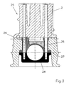
- the FIG. 3 shows a further embodiment of a cylinder crankcase 25 according to the invention with through holes 26, which may also be holes in the reinforcing member 27. This makes it possible to screw the bearing cap 28 directly to the cylinder block 2.
- the reinforcing member 29 according to the FIG. 4 is poured as a separate component 29 of gray, steel or nodular cast iron.
- the bearing 30, consisting of bearing block 31 and bearing cap 32 is poured into a component 29.
- the reinforcing member 29 is separated in the plane 33.
- the separation can be done by wire EDM or by laser or high pressure water cutting.
- By re-joining after separation optimal joining surfaces 33.
- For holding the bearing block 31 and the bearing cap 32 after the separation different possibilities are conceivable.
- the regions 39 mark the region of the reinforcing part 29, by means of which the bearing cap 32 can be screwed to the upper crankcase 3, 23 or the cylinder block 2; in this region are the threads 19 or the through bores 24, 26.
- a further object of the invention is to provide a method by means of which a cylinder crankcase according to the invention can be produced inexpensively and with minimal means.
- the storage lane that is, the reinforcing members 4, 22, 27, 29 is poured separately, then, as described above separated and reassembled and then inserted into a mold for the formation of an upper crankcase.
- the bearing 30 is filled with a mold core 40. After encapsulation of the reinforcing member 4, 22, 27, 29 of the bearing cap 32 is then separable again from the bearing block 31.
- a cylinder crankcase is provided, which in the most heavily stressed areas has a strength far beyond the strength of the base material of the cylinder crankcase 1, 21, 25 strength.
- the areas in which the screw joints 15, 19 are present, the cylinder crankcase 1, 21, 25 has grown highest tightening torques.
Landscapes
- Engineering & Computer Science (AREA)
- General Engineering & Computer Science (AREA)
- Mechanical Engineering (AREA)
- Chemical & Material Sciences (AREA)
- Combustion & Propulsion (AREA)
- Cylinder Crankcases Of Internal Combustion Engines (AREA)
- Devices For Conveying Motion By Means Of Endless Flexible Members (AREA)
- Lubrication Of Internal Combustion Engines (AREA)
- Pistons, Piston Rings, And Cylinders (AREA)
Claims (10)
- Carter de vilebrequin de cylindre de métal léger (5), notamment pour moteurs à combustion interne, comprenant au moins un élément de renforcement (4, 22, 27, 29) formé d'un seul insert encastré (6, 31) faisant office de la partie du selle d'appui (6, 31) ou formé des inserts encastré individuels (6, 31) faisant office de la partie du selle d'appui (6, 31), le ou les inserts étant encastrés dans le carter de vilebrequin de cylindre (1, 21, 25), ledit élément de renforcement (4, 22, 27, 29) étant formé d'un matériau ayant une solidité supérieure à celle du matériau de base dudit carter de vilebrequin de cylindre, caractérisé en ce que ledit carter de vilebrequin de cylindre (1, 21, 25) est formé par une unité d'espace d'eau de la glace de cylindre (2) séparée et un carter de vilebrequin (3, 23) séparé.
- Carter de vilebrequin de cylindre selon la revendication 1, caractérisé en ce que le carter de vilebrequin de cylindre (1, 21, 25) est divisé au-dessous des glaces de cylindre.
- Carter de vilebrequin de cylindre selon l'une quelconque des revendications 1 et 2, caractérisé en ce que des filets (15, 19) sont ménagées dans le carter de vilebrequin (3, 23) supérieur, ledit filet étant orienté vers le bloc de cylindre (2), et dans ledit élément de renforcement (4, 22, 27, 29), de sorte que le bloc de cylindre (2) peut être vissé au carter de vilebrequin (3, 23).
- Carter de vilebrequin de cylindre selon l'une quelconque des revendications 1 et 2, caractérisé en ce que des trous de passage (24, 26) sont ménagés dans le carter de vilebrequin (3, 23) et à travers ledit élément de renforcement (22, 27), de sorte que le bloc de cylindre (2) peut être vissé à travers le carter de vilebrequin (23) et à un chapeau de palier (32) formant le coussinet de palier (31).
- Carter de vilebrequin de cylindre selon l'une quelconque des revendications 1 à 4, caractérisé en ce que ledit élément de renforcement (4, 22, 27, 29) est réalisé en fonte moulée, acier moulé ou fonte de graphite nodulaire, et ledit carter de vilebrequin (3, 23) et ladite unité d'espace d'eau de la glace de cylindre (2) sont réalisés en un alliage d'aluminium et/ou de magnésie.
- Carter de vilebrequin de cylindre selon l'une quelconque des revendications 1 à 5, caractérisé en ce que ledit élément de renforcement (4, 22, 27, 29) est formé par un chemin de palier (29) moulé en une pièce et divisé, ledit chemin de palier (29) formant ledit élément de renforcement (31) et ledit chapeau de palier (32).
- Carter de vilebrequin de cylindre selon l'une quelconque des revendications 1 à 6, caractérisé en ce que la surface de séparation (33) dudit chemin de palier (29) présente une forme géométrique (37, 38), notamment une dentelure (38) ou un contour d'onde (37).
- Procédé de fabrication d'un carter de vilebrequin de cylindre (1, 21, 25) selon l'une quelconque des revendications précédentes, dans lequel- un chemin de palier (6, 7, 22, 27, 29, 31, 32) est moulé,- le chemin de palier (6, 7, 22, 27, 29, 31, 32) est séparé après, de sorte qu'un élément de renforcement (4, 22, 27, 31) et un capuchon de palier (7, 28, 32) sont formés,- ledit élément de renforcement (4, 22, 27, 31) et ledit capuchon de palier (7, 28, 32) sont rejoints pour former ledit chemin de palier (4, 6, 7, 22, 27, 29, 31, 32),- ledit palier de chemin (4, 6, 7, 22, 27, 29, 31, 32) est vissé à un bloc de cylindre (2) dans une moule pour un carter de vilebrequin (3, 23).
- Procédé de production d'un carter de vilebrequin de cylindre (1, 21, 25) selon la revendication 8, caractérisé en ce que ledit chemin de palier (4, 6, 7, 22, 27, 29, 31, 32) est séparé au moyen d'un laser ou au moyen d'électro-corrosion par fils ou au moyen d'une technique de jet d'eau à haute pression.
- Procédé de production d'un carter de vilebrequin de cylindre (1, 21, 25) selon l'une quelconque des revendications 8 et 9, caractérisé en ce que lors de son assemblage, ledit chemin de palier (4, 6, 7, 22, 27, 29, 31, 32) est goujonné et/ou collé et/ou joint par engagement positif.
Applications Claiming Priority (2)
| Application Number | Priority Date | Filing Date | Title |
|---|---|---|---|
| DE102006016820 | 2006-04-07 | ||
| DE102006043421A DE102006043421A1 (de) | 2006-04-07 | 2006-09-15 | Gebautes Kurbelgehäuse |
Publications (3)
| Publication Number | Publication Date |
|---|---|
| EP1843029A2 EP1843029A2 (fr) | 2007-10-10 |
| EP1843029A3 EP1843029A3 (fr) | 2009-09-09 |
| EP1843029B1 true EP1843029B1 (fr) | 2010-06-16 |
Family
ID=38180287
Family Applications (1)
| Application Number | Title | Priority Date | Filing Date |
|---|---|---|---|
| EP07003823A Not-in-force EP1843029B1 (fr) | 2006-04-07 | 2007-02-24 | Carter composité |
Country Status (3)
| Country | Link |
|---|---|
| EP (1) | EP1843029B1 (fr) |
| AT (1) | ATE471448T1 (fr) |
| DE (2) | DE102006043421A1 (fr) |
Families Citing this family (17)
| Publication number | Priority date | Publication date | Assignee | Title |
|---|---|---|---|---|
| DE102008014022A1 (de) * | 2008-03-13 | 2009-09-17 | Honsel Ag | Verfahren zur Herstellung eines Zylinderblocks sowie Zylinderblock für eine Brennkraftmaschine |
| DE102009041395A1 (de) * | 2009-09-12 | 2011-03-24 | Volkswagen Ag | Lagerdeckel-Einlegeteil |
| DE102011081516A1 (de) * | 2011-08-24 | 2013-02-28 | Mahle International Gmbh | Lagerbock |
| DE102012004887A1 (de) | 2012-03-10 | 2013-09-12 | Daimler Ag | Befestigungsanordnung eines Lagerelements an einem Kurbelgehäuse für eine Hubkolben-Verbrennungskraftmaschine |
| DE102013203565A1 (de) * | 2013-03-01 | 2014-09-04 | Bayerische Motoren Werke Aktiengesellschaft | Verfahren zur Montage eines geteilten Radiallagers und nach dem Verfahren hergestelltes geteiltes Radiallager |
| DE102013019777A1 (de) | 2013-11-23 | 2015-05-28 | Daimler Ag | Befestigungsanordnung wenigstens eines Lagerelements an einem Kurbelgehäuse einer Hubkolben-Verbrennungskraftmaschine |
| DE102013019832A1 (de) | 2013-11-23 | 2014-08-07 | Daimler Ag | Befestigungsanordnung eines Lagerelements an einem Kurbelgehäuse einer Hubkolben-Verbrennungskraftmaschine |
| US9341136B2 (en) | 2013-12-09 | 2016-05-17 | Ford Global Technologies, Llc | Engine having composite cylinder block |
| US9416749B2 (en) | 2013-12-09 | 2016-08-16 | Ford Global Technologies, Llc | Engine having composite cylinder block |
| DE102013114318B4 (de) | 2013-12-18 | 2016-09-22 | Steyr Motors Gmbh | Mehrteiliges Kurbelgehäuse und Montageverfahren |
| DE202013011394U1 (de) * | 2013-12-20 | 2015-03-23 | GM Global Technology Operations LLC (n. d. Ges. d. Staates Delaware) | Motorblock und Fahrzeug mit einem Motorblock |
| DE102014222735A1 (de) | 2014-11-06 | 2016-05-12 | Volkswagen Aktiengesellschaft | Zylinderblock für eine Verbrennungskraftmaschine und Verfahren zur Herstellung eines Zylinderblockes |
| GB2541014A (en) * | 2015-08-06 | 2017-02-08 | Gm Global Tech Operations Llc | Internal combustion engine element arrangement |
| DE102016113682A1 (de) | 2016-07-25 | 2018-01-25 | Dr. Ing. H.C. F. Porsche Aktiengesellschaft | Zylinder-Kurbelgehäuse in Leichtbauweise für Brennkraftmaschinen |
| DE102016116814A1 (de) * | 2016-09-08 | 2018-03-08 | Dr. Ing. H.C. F. Porsche Aktiengesellschaft | Zylinder-Kurbel-Gehäuse in Leichtbauweise |
| DE102020004388A1 (de) | 2020-07-22 | 2022-01-27 | Deutz Aktiengesellschaft | Zylinderkurbelgehäuse mit Fremdkörpereinschluss zur Gussreduzierung und für bessere Sauberkeit des Bauteils |
| DE102021115964A1 (de) | 2021-06-21 | 2022-12-22 | Neander Motors Aktiengesellschaft | Hubkolbenmotor mit einem Zylindergehäuse und mit einem mit diesem verbundenen Kurbelgehäuse |
Family Cites Families (4)
| Publication number | Priority date | Publication date | Assignee | Title |
|---|---|---|---|---|
| DE19604547B4 (de) * | 1995-02-17 | 2007-01-04 | Volkswagen Ag | Gehäuse für eine Hubkolbenbrennkraftmaschine |
| DE19537191A1 (de) * | 1995-10-06 | 1997-04-10 | Porsche Ag | Kurbelwellenlagerung für eine Brennkraftmaschine |
| US6076971A (en) * | 1997-07-01 | 2000-06-20 | Cummins Engine Company, Inc. | Engine block bearing saddle reinforcing inserts |
| JP2000205037A (ja) * | 1999-01-13 | 2000-07-25 | Isuzu Motors Ltd | シリンダブロック |
-
2006
- 2006-09-15 DE DE102006043421A patent/DE102006043421A1/de not_active Ceased
-
2007
- 2007-02-24 AT AT07003823T patent/ATE471448T1/de active
- 2007-02-24 DE DE502007004109T patent/DE502007004109D1/de active Active
- 2007-02-24 EP EP07003823A patent/EP1843029B1/fr not_active Not-in-force
Also Published As
| Publication number | Publication date |
|---|---|
| ATE471448T1 (de) | 2010-07-15 |
| DE102006043421A1 (de) | 2007-10-18 |
| EP1843029A3 (fr) | 2009-09-09 |
| DE502007004109D1 (de) | 2010-07-29 |
| EP1843029A2 (fr) | 2007-10-10 |
Similar Documents
| Publication | Publication Date | Title |
|---|---|---|
| EP1843029B1 (fr) | Carter composité | |
| EP1919644B1 (fr) | Procédé de fabrication d'un composant coulé avec un tube coulé | |
| EP1570167B1 (fr) | Composant coule destine a un moteur a combustion interne | |
| DE10026216B4 (de) | Zylinder-Kurbelgehäuse für eine Brennkraftmaschine | |
| EP2063094B1 (fr) | Composant coulé pour un moteur à combustion interne | |
| DE102016102391A1 (de) | Trennwandeinsatz für einen verbrennungsmotor | |
| DE102018130218A1 (de) | Verbund-Motorarchitektur und Verfahren zur Herstellung derselben | |
| EP3310509B1 (fr) | Moteur à combustion interne à pistons et procédé de fabrication d'un moteur à combustion interne à piston | |
| EP0883740B1 (fr) | Moteur a combustion interne et son procede de fabrication | |
| EP2340901B1 (fr) | Procédé de fabrication d'une pièce en fonte | |
| EP0771944B1 (fr) | Bâtiment pour un moteur à combustion interne aux pistons | |
| DE112004002493T5 (de) | Vereinfachte Motorarchitektur und Motorbaugruppe | |
| DE10235911B3 (de) | Gussverbund von Hohlprofilen aus Leichtmetall-Legierung und Verfahren zu seiner Herstellung | |
| DE10221674B4 (de) | Verfahren zum Herstellen eines Zylindergehäuses und Zylindergehäuse | |
| EP0851132A1 (fr) | Boítier moulé comprenant un ensemble de palier, notamment ensemble bloc cylindre-carter de vilebrequin pour machine à pistons alternatifs | |
| DE102004040539B4 (de) | Zylinder-Kurbelgehäuse für eine Mehrzylinder-Hubkolbenmaschine sowie Verfahren zur Herstellung eines Zylinder-Kurbelgehäuses für eine Mehrzylinder-Hubkolbenmaschine | |
| DE10032845A1 (de) | Zylinderkurbelgehäuse für Verbrennungskraftmaschine | |
| DE102005048650B4 (de) | Fertigungsverfahren und Bauweise für Gussbauteile mit Formhohlräumen | |
| WO2006048111A1 (fr) | Element constitutif renforce | |
| DE10205958A1 (de) | Verfahren zur Herstellung eines Leichtmetallbauteils und Eingussteil | |
| DE10221673B4 (de) | Zylinderliner zum Eingießen in ein Zylindergehäuse | |
| DE102005041340A1 (de) | Zylinderkurbelgehäuse für eine Brennkraftmaschine | |
| DE3404866C1 (de) | Gegossener Zylinderblock für eine Hubkolbenmaschine sowie Vorrichtung zum Gießen eines derartigen Zylinderblockes | |
| DE10221675A1 (de) | Zylindergehäuse | |
| DE10121861B4 (de) | Aus Leichtmetallwerkstoff gegossenes Motorelement und Verstärkungselement |
Legal Events
| Date | Code | Title | Description |
|---|---|---|---|
| PUAI | Public reference made under article 153(3) epc to a published international application that has entered the european phase |
Free format text: ORIGINAL CODE: 0009012 |
|
| 17P | Request for examination filed |
Effective date: 20070531 |
|
| AK | Designated contracting states |
Kind code of ref document: A2 Designated state(s): AT BE BG CH CY CZ DE DK EE ES FI FR GB GR HU IE IS IT LI LT LU LV MC NL PL PT RO SE SI SK TR |
|
| AX | Request for extension of the european patent |
Extension state: AL BA HR MK YU |
|
| RAP1 | Party data changed (applicant data changed or rights of an application transferred) |
Owner name: KS ALUMINIUM-TECHNOLOGIE GMBH |
|
| PUAL | Search report despatched |
Free format text: ORIGINAL CODE: 0009013 |
|
| AK | Designated contracting states |
Kind code of ref document: A3 Designated state(s): AT BE BG CH CY CZ DE DK EE ES FI FR GB GR HU IE IS IT LI LT LU LV MC NL PL PT RO SE SI SK TR |
|
| AX | Request for extension of the european patent |
Extension state: AL BA HR MK RS |
|
| GRAP | Despatch of communication of intention to grant a patent |
Free format text: ORIGINAL CODE: EPIDOSNIGR1 |
|
| GRAS | Grant fee paid |
Free format text: ORIGINAL CODE: EPIDOSNIGR3 |
|
| AKX | Designation fees paid |
Designated state(s): AT BE BG CH CY CZ DE DK EE ES FI FR GB GR HU IE IS IT LI LT LU LV MC NL PL PT RO SE SI SK TR |
|
| GRAA | (expected) grant |
Free format text: ORIGINAL CODE: 0009210 |
|
| AK | Designated contracting states |
Kind code of ref document: B1 Designated state(s): AT BE BG CH CY CZ DE DK EE ES FI FR GB GR HU IE IS IT LI LT LU LV MC NL PL PT RO SE SI SK TR |
|
| REG | Reference to a national code |
Ref country code: CH Ref legal event code: EP |
|
| REG | Reference to a national code |
Ref country code: IE Ref legal event code: FG4D Free format text: LANGUAGE OF EP DOCUMENT: GERMAN |
|
| REF | Corresponds to: |
Ref document number: 502007004109 Country of ref document: DE Date of ref document: 20100729 Kind code of ref document: P |
|
| REG | Reference to a national code |
Ref country code: NL Ref legal event code: VDEP Effective date: 20100616 |
|
| PG25 | Lapsed in a contracting state [announced via postgrant information from national office to epo] |
Ref country code: SE Free format text: LAPSE BECAUSE OF FAILURE TO SUBMIT A TRANSLATION OF THE DESCRIPTION OR TO PAY THE FEE WITHIN THE PRESCRIBED TIME-LIMIT Effective date: 20100616 Ref country code: LT Free format text: LAPSE BECAUSE OF FAILURE TO SUBMIT A TRANSLATION OF THE DESCRIPTION OR TO PAY THE FEE WITHIN THE PRESCRIBED TIME-LIMIT Effective date: 20100616 |
|
| LTIE | Lt: invalidation of european patent or patent extension |
Effective date: 20100616 |
|
| PG25 | Lapsed in a contracting state [announced via postgrant information from national office to epo] |
Ref country code: FI Free format text: LAPSE BECAUSE OF FAILURE TO SUBMIT A TRANSLATION OF THE DESCRIPTION OR TO PAY THE FEE WITHIN THE PRESCRIBED TIME-LIMIT Effective date: 20100616 Ref country code: SI Free format text: LAPSE BECAUSE OF FAILURE TO SUBMIT A TRANSLATION OF THE DESCRIPTION OR TO PAY THE FEE WITHIN THE PRESCRIBED TIME-LIMIT Effective date: 20100616 Ref country code: LV Free format text: LAPSE BECAUSE OF FAILURE TO SUBMIT A TRANSLATION OF THE DESCRIPTION OR TO PAY THE FEE WITHIN THE PRESCRIBED TIME-LIMIT Effective date: 20100616 |
|
| PG25 | Lapsed in a contracting state [announced via postgrant information from national office to epo] |
Ref country code: PL Free format text: LAPSE BECAUSE OF FAILURE TO SUBMIT A TRANSLATION OF THE DESCRIPTION OR TO PAY THE FEE WITHIN THE PRESCRIBED TIME-LIMIT Effective date: 20100616 Ref country code: CY Free format text: LAPSE BECAUSE OF FAILURE TO SUBMIT A TRANSLATION OF THE DESCRIPTION OR TO PAY THE FEE WITHIN THE PRESCRIBED TIME-LIMIT Effective date: 20100616 |
|
| REG | Reference to a national code |
Ref country code: IE Ref legal event code: FD4D |
|
| PG25 | Lapsed in a contracting state [announced via postgrant information from national office to epo] |
Ref country code: IE Free format text: LAPSE BECAUSE OF FAILURE TO SUBMIT A TRANSLATION OF THE DESCRIPTION OR TO PAY THE FEE WITHIN THE PRESCRIBED TIME-LIMIT Effective date: 20100616 Ref country code: EE Free format text: LAPSE BECAUSE OF FAILURE TO SUBMIT A TRANSLATION OF THE DESCRIPTION OR TO PAY THE FEE WITHIN THE PRESCRIBED TIME-LIMIT Effective date: 20100616 Ref country code: GR Free format text: LAPSE BECAUSE OF FAILURE TO SUBMIT A TRANSLATION OF THE DESCRIPTION OR TO PAY THE FEE WITHIN THE PRESCRIBED TIME-LIMIT Effective date: 20100917 Ref country code: NL Free format text: LAPSE BECAUSE OF FAILURE TO SUBMIT A TRANSLATION OF THE DESCRIPTION OR TO PAY THE FEE WITHIN THE PRESCRIBED TIME-LIMIT Effective date: 20100616 |
|
| PG25 | Lapsed in a contracting state [announced via postgrant information from national office to epo] |
Ref country code: SK Free format text: LAPSE BECAUSE OF FAILURE TO SUBMIT A TRANSLATION OF THE DESCRIPTION OR TO PAY THE FEE WITHIN THE PRESCRIBED TIME-LIMIT Effective date: 20100616 Ref country code: IS Free format text: LAPSE BECAUSE OF FAILURE TO SUBMIT A TRANSLATION OF THE DESCRIPTION OR TO PAY THE FEE WITHIN THE PRESCRIBED TIME-LIMIT Effective date: 20101016 Ref country code: PT Free format text: LAPSE BECAUSE OF FAILURE TO SUBMIT A TRANSLATION OF THE DESCRIPTION OR TO PAY THE FEE WITHIN THE PRESCRIBED TIME-LIMIT Effective date: 20101018 Ref country code: CZ Free format text: LAPSE BECAUSE OF FAILURE TO SUBMIT A TRANSLATION OF THE DESCRIPTION OR TO PAY THE FEE WITHIN THE PRESCRIBED TIME-LIMIT Effective date: 20100616 Ref country code: RO Free format text: LAPSE BECAUSE OF FAILURE TO SUBMIT A TRANSLATION OF THE DESCRIPTION OR TO PAY THE FEE WITHIN THE PRESCRIBED TIME-LIMIT Effective date: 20100616 |
|
| PG25 | Lapsed in a contracting state [announced via postgrant information from national office to epo] |
Ref country code: IT Free format text: LAPSE BECAUSE OF FAILURE TO SUBMIT A TRANSLATION OF THE DESCRIPTION OR TO PAY THE FEE WITHIN THE PRESCRIBED TIME-LIMIT Effective date: 20100616 |
|
| PLBE | No opposition filed within time limit |
Free format text: ORIGINAL CODE: 0009261 |
|
| STAA | Information on the status of an ep patent application or granted ep patent |
Free format text: STATUS: NO OPPOSITION FILED WITHIN TIME LIMIT |
|
| PG25 | Lapsed in a contracting state [announced via postgrant information from national office to epo] |
Ref country code: DK Free format text: LAPSE BECAUSE OF FAILURE TO SUBMIT A TRANSLATION OF THE DESCRIPTION OR TO PAY THE FEE WITHIN THE PRESCRIBED TIME-LIMIT Effective date: 20100616 |
|
| 26N | No opposition filed |
Effective date: 20110317 |
|
| REG | Reference to a national code |
Ref country code: DE Ref legal event code: R097 Ref document number: 502007004109 Country of ref document: DE Effective date: 20110316 |
|
| BERE | Be: lapsed |
Owner name: KS ALUMINIUM-TECHNOLOGIE G.M.B.H. Effective date: 20110228 |
|
| PG25 | Lapsed in a contracting state [announced via postgrant information from national office to epo] |
Ref country code: MC Free format text: LAPSE BECAUSE OF NON-PAYMENT OF DUE FEES Effective date: 20110228 |
|
| REG | Reference to a national code |
Ref country code: CH Ref legal event code: PL |
|
| GBPC | Gb: european patent ceased through non-payment of renewal fee |
Effective date: 20110224 |
|
| PG25 | Lapsed in a contracting state [announced via postgrant information from national office to epo] |
Ref country code: LI Free format text: LAPSE BECAUSE OF NON-PAYMENT OF DUE FEES Effective date: 20110228 Ref country code: CH Free format text: LAPSE BECAUSE OF NON-PAYMENT OF DUE FEES Effective date: 20110228 |
|
| REG | Reference to a national code |
Ref country code: FR Ref legal event code: ST Effective date: 20111102 |
|
| PG25 | Lapsed in a contracting state [announced via postgrant information from national office to epo] |
Ref country code: BE Free format text: LAPSE BECAUSE OF NON-PAYMENT OF DUE FEES Effective date: 20110228 |
|
| PG25 | Lapsed in a contracting state [announced via postgrant information from national office to epo] |
Ref country code: FR Free format text: LAPSE BECAUSE OF NON-PAYMENT OF DUE FEES Effective date: 20110228 |
|
| PG25 | Lapsed in a contracting state [announced via postgrant information from national office to epo] |
Ref country code: GB Free format text: LAPSE BECAUSE OF NON-PAYMENT OF DUE FEES Effective date: 20110224 |
|
| REG | Reference to a national code |
Ref country code: AT Ref legal event code: MM01 Ref document number: 471448 Country of ref document: AT Kind code of ref document: T Effective date: 20120224 |
|
| PG25 | Lapsed in a contracting state [announced via postgrant information from national office to epo] |
Ref country code: LU Free format text: LAPSE BECAUSE OF NON-PAYMENT OF DUE FEES Effective date: 20110224 |
|
| PG25 | Lapsed in a contracting state [announced via postgrant information from national office to epo] |
Ref country code: AT Free format text: LAPSE BECAUSE OF NON-PAYMENT OF DUE FEES Effective date: 20120224 |
|
| PG25 | Lapsed in a contracting state [announced via postgrant information from national office to epo] |
Ref country code: TR Free format text: LAPSE BECAUSE OF FAILURE TO SUBMIT A TRANSLATION OF THE DESCRIPTION OR TO PAY THE FEE WITHIN THE PRESCRIBED TIME-LIMIT Effective date: 20100616 Ref country code: BG Free format text: LAPSE BECAUSE OF FAILURE TO SUBMIT A TRANSLATION OF THE DESCRIPTION OR TO PAY THE FEE WITHIN THE PRESCRIBED TIME-LIMIT Effective date: 20100916 |
|
| PG25 | Lapsed in a contracting state [announced via postgrant information from national office to epo] |
Ref country code: HU Free format text: LAPSE BECAUSE OF FAILURE TO SUBMIT A TRANSLATION OF THE DESCRIPTION OR TO PAY THE FEE WITHIN THE PRESCRIBED TIME-LIMIT Effective date: 20100616 Ref country code: ES Free format text: LAPSE BECAUSE OF FAILURE TO SUBMIT A TRANSLATION OF THE DESCRIPTION OR TO PAY THE FEE WITHIN THE PRESCRIBED TIME-LIMIT Effective date: 20100927 |
|
| REG | Reference to a national code |
Ref country code: DE Ref legal event code: R082 Ref document number: 502007004109 Country of ref document: DE Representative=s name: PATENTANWAELTE TER SMITTEN EBERLEIN RUETTEN PA, DE Ref country code: DE Ref legal event code: R081 Ref document number: 502007004109 Country of ref document: DE Owner name: KS HUAYU ALUTECH GMBH, DE Free format text: FORMER OWNER: KS ALUMINIUM-TECHNOLOGIE GMBH, 74172 NECKARSULM, DE Ref country code: DE Ref legal event code: R082 Ref document number: 502007004109 Country of ref document: DE Representative=s name: PATENTANWAELTE TER SMITTEN EBERLEIN-VAN HOOF R, DE |
|
| REG | Reference to a national code |
Ref country code: DE Ref legal event code: R082 Ref document number: 502007004109 Country of ref document: DE Representative=s name: TERPATENT PATENTANWAELTE TER SMITTEN EBERLEIN-, DE |
|
| PGFP | Annual fee paid to national office [announced via postgrant information from national office to epo] |
Ref country code: DE Payment date: 20200220 Year of fee payment: 14 |
|
| REG | Reference to a national code |
Ref country code: DE Ref legal event code: R119 Ref document number: 502007004109 Country of ref document: DE |
|
| PG25 | Lapsed in a contracting state [announced via postgrant information from national office to epo] |
Ref country code: DE Free format text: LAPSE BECAUSE OF NON-PAYMENT OF DUE FEES Effective date: 20210901 |