EP1843069A1 - Dispositif d'arrêt avec dispositif indicateur - Google Patents
Dispositif d'arrêt avec dispositif indicateur Download PDFInfo
- Publication number
- EP1843069A1 EP1843069A1 EP06007204A EP06007204A EP1843069A1 EP 1843069 A1 EP1843069 A1 EP 1843069A1 EP 06007204 A EP06007204 A EP 06007204A EP 06007204 A EP06007204 A EP 06007204A EP 1843069 A1 EP1843069 A1 EP 1843069A1
- Authority
- EP
- European Patent Office
- Prior art keywords
- shut
- display device
- recess
- bore
- valve housing
- Prior art date
- Legal status (The legal status is an assumption and is not a legal conclusion. Google has not performed a legal analysis and makes no representation as to the accuracy of the status listed.)
- Withdrawn
Links
Images


Classifications
-
- F—MECHANICAL ENGINEERING; LIGHTING; HEATING; WEAPONS; BLASTING
- F16—ENGINEERING ELEMENTS AND UNITS; GENERAL MEASURES FOR PRODUCING AND MAINTAINING EFFECTIVE FUNCTIONING OF MACHINES OR INSTALLATIONS; THERMAL INSULATION IN GENERAL
- F16K—VALVES; TAPS; COCKS; ACTUATING-FLOATS; DEVICES FOR VENTING OR AERATING
- F16K37/00—Special means in or on valves or other cut-off apparatus for indicating or recording operation thereof, or for enabling an alarm to be given
- F16K37/0066—Hydraulic or pneumatic means
-
- F—MECHANICAL ENGINEERING; LIGHTING; HEATING; WEAPONS; BLASTING
- F16—ENGINEERING ELEMENTS AND UNITS; GENERAL MEASURES FOR PRODUCING AND MAINTAINING EFFECTIVE FUNCTIONING OF MACHINES OR INSTALLATIONS; THERMAL INSULATION IN GENERAL
- F16K—VALVES; TAPS; COCKS; ACTUATING-FLOATS; DEVICES FOR VENTING OR AERATING
- F16K37/00—Special means in or on valves or other cut-off apparatus for indicating or recording operation thereof, or for enabling an alarm to be given
- F16K37/0058—Optical means, e.g. light transmission, observation ports
-
- F—MECHANICAL ENGINEERING; LIGHTING; HEATING; WEAPONS; BLASTING
- F16—ENGINEERING ELEMENTS AND UNITS; GENERAL MEASURES FOR PRODUCING AND MAINTAINING EFFECTIVE FUNCTIONING OF MACHINES OR INSTALLATIONS; THERMAL INSULATION IN GENERAL
- F16K—VALVES; TAPS; COCKS; ACTUATING-FLOATS; DEVICES FOR VENTING OR AERATING
- F16K5/00—Plug valves; Taps or cocks comprising only cut-off apparatus having at least one of the sealing faces shaped as a more or less complete surface of a solid of revolution, the opening and closing movement being predominantly rotary
- F16K5/06—Plug valves; Taps or cocks comprising only cut-off apparatus having at least one of the sealing faces shaped as a more or less complete surface of a solid of revolution, the opening and closing movement being predominantly rotary with plugs having spherical surfaces; Packings therefor
- F16K5/0605—Plug valves; Taps or cocks comprising only cut-off apparatus having at least one of the sealing faces shaped as a more or less complete surface of a solid of revolution, the opening and closing movement being predominantly rotary with plugs having spherical surfaces; Packings therefor with particular plug arrangements, e.g. particular shape or built-in means
Definitions
- the invention relates to a shut-off device with a display device comprising a valve housing having at least two connection areas for connection to mediumsstageden piping, a valve housing between the connection areas about a perpendicular axis to the flow direction rotatably mounted shut-off member and rotatably mounted in the valve housing about the axis of rotation and with connectable to the shut-off link, wherein the connecting member during the rotational movement of the shut-off from a first open position to a second closed position describes a rotation angle of about 90 °.
- valves In pipeline construction, pipelines are shut off with valves that are operated manually or by motor. For valves that are operated with external energy, and / or valves that are arranged difficult to access, the valve position can not always be clearly recognized. When manually operated valves, the position of the obturator can often be derived from the position of the handle. However, it can not be deduced from the position of the shut-off element alone whether the pipeline is filled with medium or not. For this purpose, flow monitors are usually installed in front of or behind the valve in the pipeline.
- the valve stem protrudes from the actuator housing with one end at the top of the valve.
- the spindle end is arranged in a further hat-shaped or cylindrical housing above the actuating housing.
- the hat-shaped housing is made of a transparent material.
- On the circumference of the spindle end and on the inside of the hat-shaped housing are shown with color or other coating checkerboard pattern.
- the rotation of the spindle by 90 ° the checkerboard patterns are either side by side arranged or aligned with each other. If the checkerboard pattern is sufficiently large and / or formed in clearly visible signal colors, the valve position of the rotary valve can be observed from a greater distance.
- the display is directly linked to the movement of the valve stem.
- a shut-off device with a display device comprising a valve housing having at least two connection areas for connection to medium-carrying pipelines, a shut-off member rotatably mounted in the valve housing between the connection areas about an axis perpendicular to the flow direction and a valve housing rotatably mounted about the axis of rotation and with the connection member connectable to the shut-off member, wherein the connecting member during the rotational movement of the shut-off from a first open position to a second closed position describes a rotation angle of about 90 °, wherein the connecting member has a about the axis of rotation extending substantially cylindrically shaped and the shut-off member open towards recess ,
- the display device can be used even with the handle removed, ie without an actuator. This is achieved in that a float is arranged in the recess in the connecting member as a display device.
- the display device can also be used with the closed shut-off member for indicating the presence of the medium.
- the shut-off member has a further connection bore perpendicular to the first bore.
- the basic idea of the invention is to develop in a piping system, for example a ball valve, without additional installations an indication of the flow and pressure conditions, which works independently of the movement of the actuator, which can be integrated without additional installations in existing shut-offs and in relatively large distance is as visible as possible.
- FIG. 1 shows schematically a part of a shut-off device 10 with a display device 20.
- a shut-off member 1 here a ball valve 2 of a ball valve seen perpendicular to the flow direction.
- the ball valve 2 is arranged rotatably about a rotation axis X, also perpendicular to the flow direction.
- dashed lines is schematic a valve housing 3 with sealing arrangements 4.5 indicated.
- the shut-off member is rotatably mounted in the valve housing 3 between the seals 4,5.
- the valve housing 3 has a connection region 6 on both sides for connection to a medium-carrying pipeline.
- a connecting member 7 between the ball valve 2 and a schematically illustrated actuator 8, is arranged.
- the connecting member 7, or the valve stem 7, is connected against rotation with the ball plug 2 and rotatably mounted in a neck region 9 of the valve housing 3.
- the valve spindle 7 has a cylindrically shaped recess 11.
- the recess extends in the direction of the axis of rotation X and is open towards the bottom.
- a further bore 12 is formed in the ball valve 2.
- the bore 12 forms a channel for the medium that flows through the shut-off member 1 in the open state. Because the bore 12 and the recess 11 are both arranged in the direction of the axis of rotation X, regardless of the position of the shut-off member 7, even in the closed state of the shut-off member 1, the connection from the recess 11 to the media passage 13 of the ball joint 3 ensured.
- a float 14 is shown schematically.
- FIG. 2 shows another view of a shut-off element, here a ball plug 2 together with a valve spindle 7.
- the valve spindle 7 has at the upper end a bore 16 which is arranged perpendicular to the axis of rotation X and is in communication with the recess 11.
- the bore 16 serves as an overflow or outlet for the medium and / or the air, which are displaced in the movement of the float 14 upwards in the recess 11 of the spindle 7.
- the overflow hole 16 opens into a channel 17 with a U-shaped cross-section. This channel 17 ensures that the medium can flow even when plugged actuator 8.
- the overflow bore 16 extends perpendicular to the axis of rotation X of the valve spindle 7, that is parallel to the pipe axis.
- the Overflow hole 16 subsequent to the recess 11 prevents the recess 11 from being dirty and clogged from the outside.
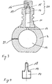
- FIG 3 shows a section along the line A-A of Figure 2.
- the floating body 14 is freely movable in the direction of the axis of rotation X in the recess 11, that is rotatable about the X-axis and linearly displaceable arranged.
- the float 14 is in the recess 11 in the uppermost position, i. in a loaded with the medium pressure position shown.
- an O-ring seal 15 can be seen, which serves as a stop and seal for the floating body 14 at the end of the recess 11. The O-ring seal 15 prevents in the upper position of the floating body 14 medium is lost from the pipeline.
- the floating body 14 is shown by itself.
- the floating body 14 is rotationally symmetrical and has a special shape.
- the float 14 has at the upper end a projection 18 which simplifies the recording and the leadership of the floating body 14 into the recess 11 of the spindle 7 and ensures.
- the floating body 14 has a groove 19 is formed on the V-shaped, and which ensures the sealing receiving the O-ring seal 15.
- the recess 11 of the valve stem 7, in particular the upper part, which receives the projection 18 has been designed so that the Venturi effect is reduced or suppressed in the movement of the float 14 in the recess 11.
- the display device 20 thus does not lead to a greater loss of media.
- the amount of the emerging into the overflow hole 16 medium is so small that the external environment of the valve is not loaded.
- the valve spindle 7 is made of a transparent material, at least in the region between the valve housing 3 and the actuator 8. The visibility of the display device 20 is increased when the float 14 is made in a clearly visible color, such as yellow, orange or red.
- the display device 20 described here can be observed in a simple manner from a great distance, and from all sides around the valve, whether in the pipeline flowing and / or pressurized medium is present.
- a statement about the position of the shut-off member 1 can be made.
- the linear movement of the floating body 14 in the direction of the axis of rotation X is independent of the rotational movement of the valve stem 7 about the axis of rotation X.
- the display also works with the handle 8 removed or when the operation of the valve is controlled by a motor.
- the display device 20 can also be formed in all other shut-off members 1, which are provided with a spindle for actuation.
- the display device 20 is particularly suitable for displaying the valve position and the flow in piping systems, for example in agriculture or water treatment.
- the display device can be used anywhere where neither electrical power or other means for signaling the flow are available and where the visual control is sufficient.
- the integrated in the shut-off device 10 display 20 ensures a compact and unbreakable arrangement and requires no additional installation of valves such as pressure gauge, flow monitor or flow meter.
Landscapes
- Engineering & Computer Science (AREA)
- General Engineering & Computer Science (AREA)
- Mechanical Engineering (AREA)
- Taps Or Cocks (AREA)
- Indication Of The Valve Opening Or Closing Status (AREA)
Priority Applications (1)
| Application Number | Priority Date | Filing Date | Title |
|---|---|---|---|
| EP06007204A EP1843069A1 (fr) | 2006-04-05 | 2006-04-05 | Dispositif d'arrêt avec dispositif indicateur |
Applications Claiming Priority (1)
| Application Number | Priority Date | Filing Date | Title |
|---|---|---|---|
| EP06007204A EP1843069A1 (fr) | 2006-04-05 | 2006-04-05 | Dispositif d'arrêt avec dispositif indicateur |
Publications (1)
| Publication Number | Publication Date |
|---|---|
| EP1843069A1 true EP1843069A1 (fr) | 2007-10-10 |
Family
ID=36928805
Family Applications (1)
| Application Number | Title | Priority Date | Filing Date |
|---|---|---|---|
| EP06007204A Withdrawn EP1843069A1 (fr) | 2006-04-05 | 2006-04-05 | Dispositif d'arrêt avec dispositif indicateur |
Country Status (1)
| Country | Link |
|---|---|
| EP (1) | EP1843069A1 (fr) |
Cited By (1)
| Publication number | Priority date | Publication date | Assignee | Title |
|---|---|---|---|---|
| WO2008106031A1 (fr) * | 2007-02-28 | 2008-09-04 | Itt Manufacturing Enterprises, Inc. | Orifice intégré dans une tige de soupape |
Citations (5)
| Publication number | Priority date | Publication date | Assignee | Title |
|---|---|---|---|---|
| DE7540606U (de) * | 1975-12-19 | 1976-07-15 | Siemens Ag, 1000 Berlin Und 8000 Muenchen | Drehventil |
| EP0092714A1 (fr) * | 1982-04-09 | 1983-11-02 | Westlock Control Corporation | Dispositif d'indication de position et utilisation avec dispositif de soupape |
| EP0200563A2 (fr) * | 1985-05-03 | 1986-11-05 | Robert James Weir | Vanne pour conduite de processus |
| DE9312879U1 (de) * | 1993-08-27 | 1993-10-21 | EBRO-Armaturen Gebr. Bröer GmbH, 58135 Hagen | Absperrarmatur |
| DE4425698A1 (de) * | 1994-07-20 | 1996-01-25 | Buerkert Werke Gmbh & Co | Absperr- und/oder Stellorgan |
-
2006
- 2006-04-05 EP EP06007204A patent/EP1843069A1/fr not_active Withdrawn
Patent Citations (5)
| Publication number | Priority date | Publication date | Assignee | Title |
|---|---|---|---|---|
| DE7540606U (de) * | 1975-12-19 | 1976-07-15 | Siemens Ag, 1000 Berlin Und 8000 Muenchen | Drehventil |
| EP0092714A1 (fr) * | 1982-04-09 | 1983-11-02 | Westlock Control Corporation | Dispositif d'indication de position et utilisation avec dispositif de soupape |
| EP0200563A2 (fr) * | 1985-05-03 | 1986-11-05 | Robert James Weir | Vanne pour conduite de processus |
| DE9312879U1 (de) * | 1993-08-27 | 1993-10-21 | EBRO-Armaturen Gebr. Bröer GmbH, 58135 Hagen | Absperrarmatur |
| DE4425698A1 (de) * | 1994-07-20 | 1996-01-25 | Buerkert Werke Gmbh & Co | Absperr- und/oder Stellorgan |
Cited By (2)
| Publication number | Priority date | Publication date | Assignee | Title |
|---|---|---|---|---|
| WO2008106031A1 (fr) * | 2007-02-28 | 2008-09-04 | Itt Manufacturing Enterprises, Inc. | Orifice intégré dans une tige de soupape |
| US7828012B2 (en) | 2007-02-28 | 2010-11-09 | Itt Manufacturing Enterprises, Inc. | Port integrated within valve stem |
Similar Documents
| Publication | Publication Date | Title |
|---|---|---|
| DE102009011343B4 (de) | Durchflussmengenregler | |
| EP3259506A1 (fr) | Soupape pour réguler le flux d'eau dans une conduite sanitaire | |
| DE102007026162A1 (de) | Absperrvorrichtung | |
| DE102011013097A1 (de) | Kugelhahn | |
| EP1525417B1 (fr) | Vanne, en particulier vanne de prise de vapeur | |
| EP1649201B2 (fr) | Soupape a voies multiples | |
| DE4425698B4 (de) | Absperr- und/oder Stellorgan | |
| EP1843069A1 (fr) | Dispositif d'arrêt avec dispositif indicateur | |
| EP0943901B1 (fr) | Raccord pour un dispositif de mesure de débit d'un liquide | |
| DE20219008U1 (de) | Wasserarmatur | |
| EP4008844B1 (fr) | Système de protection contre les fuites | |
| DE102006040872A1 (de) | Kugelhahnanordnung | |
| AT403440B (de) | Alarmventilstation | |
| EP2672153B1 (fr) | Robinet à boisseau sphérique | |
| EP2416138A2 (fr) | Dispositif de mesure et système pour installer un capteur de température dans un espace de mesure | |
| DE4030104C2 (de) | Strangregulierventil | |
| DE19636410B4 (de) | Armatur für Wasserleitungen | |
| EP1070889A2 (fr) | Soupape de contrôle axiale | |
| EP2149729A1 (fr) | Vanne à boisseau sphérique dotée d'une connexion en T | |
| DE102021121780A1 (de) | Anschlussanordnung mit Absperrung | |
| EP2076702A1 (fr) | Vanne de régulation de débit | |
| DE10255522B4 (de) | Ventil mit Durchflussmesser | |
| EP1780454B1 (fr) | Dispositif destiné au remplissage automatique de liquides | |
| DE60204386T2 (de) | Vorrichtung zur Durchflussteuerung in einem hydraulischen Verteiler | |
| DE8613517U1 (de) | Wechselventil für 2 Sicherheitsventile |
Legal Events
| Date | Code | Title | Description |
|---|---|---|---|
| PUAI | Public reference made under article 153(3) epc to a published international application that has entered the european phase |
Free format text: ORIGINAL CODE: 0009012 |
|
| AK | Designated contracting states |
Kind code of ref document: A1 Designated state(s): AT BE BG CH CY CZ DE DK EE ES FI FR GB GR HU IE IS IT LI LT LU LV MC NL PL PT RO SE SI SK TR |
|
| AX | Request for extension of the european patent |
Extension state: AL BA HR MK YU |
|
| AKX | Designation fees paid | ||
| REG | Reference to a national code |
Ref country code: DE Ref legal event code: 8566 |
|
| STAA | Information on the status of an ep patent application or granted ep patent |
Free format text: STATUS: THE APPLICATION IS DEEMED TO BE WITHDRAWN |
|
| 18D | Application deemed to be withdrawn |
Effective date: 20080411 |