EP1843122B1 - Dispositif de réglage - Google Patents
Dispositif de réglage Download PDFInfo
- Publication number
- EP1843122B1 EP1843122B1 EP07005733A EP07005733A EP1843122B1 EP 1843122 B1 EP1843122 B1 EP 1843122B1 EP 07005733 A EP07005733 A EP 07005733A EP 07005733 A EP07005733 A EP 07005733A EP 1843122 B1 EP1843122 B1 EP 1843122B1
- Authority
- EP
- European Patent Office
- Prior art keywords
- adjusting device
- click
- appliance
- stop
- adjusting
- Prior art date
- Legal status (The legal status is an assumption and is not a legal conclusion. Google has not performed a legal analysis and makes no representation as to the accuracy of the status listed.)
- Active
Links
Images




Classifications
-
- F—MECHANICAL ENGINEERING; LIGHTING; HEATING; WEAPONS; BLASTING
- F41—WEAPONS
- F41G—WEAPON SIGHTS; AIMING
- F41G1/00—Sighting devices
- F41G1/38—Telescopic sights specially adapted for smallarms or ordnance; Supports or mountings therefor
-
- F—MECHANICAL ENGINEERING; LIGHTING; HEATING; WEAPONS; BLASTING
- F41—WEAPONS
- F41G—WEAPON SIGHTS; AIMING
- F41G1/00—Sighting devices
- F41G1/06—Rearsights
- F41G1/16—Adjusting mechanisms therefor; Mountings therefor
- F41G1/18—Clicking-indicators with spring detents
-
- G—PHYSICS
- G05—CONTROLLING; REGULATING
- G05G—CONTROL DEVICES OR SYSTEMS INSOFAR AS CHARACTERISED BY MECHANICAL FEATURES ONLY
- G05G1/00—Controlling members, e.g. knobs or handles; Assemblies or arrangements thereof; Indicating position of controlling members
- G05G1/015—Arrangements for indicating the position of a controlling member
-
- G—PHYSICS
- G05—CONTROLLING; REGULATING
- G05G—CONTROL DEVICES OR SYSTEMS INSOFAR AS CHARACTERISED BY MECHANICAL FEATURES ONLY
- G05G1/00—Controlling members, e.g. knobs or handles; Assemblies or arrangements thereof; Indicating position of controlling members
- G05G1/08—Controlling members for hand actuation by rotary movement, e.g. hand wheels
-
- G—PHYSICS
- G02—OPTICS
- G02B—OPTICAL ELEMENTS, SYSTEMS OR APPARATUS
- G02B23/00—Telescopes, e.g. binoculars; Periscopes; Instruments for viewing the inside of hollow bodies; Viewfinders; Optical aiming or sighting devices
- G02B23/02—Telescopes, e.g. binoculars; Periscopes; Instruments for viewing the inside of hollow bodies; Viewfinders; Optical aiming or sighting devices involving prisms or mirrors
- G02B23/10—Telescopes, e.g. binoculars; Periscopes; Instruments for viewing the inside of hollow bodies; Viewfinders; Optical aiming or sighting devices involving prisms or mirrors reflecting into the field of view additional indications, e.g. from collimator
- G02B23/105—Sighting devices with light source and collimating reflector
-
- G—PHYSICS
- G02—OPTICS
- G02B—OPTICAL ELEMENTS, SYSTEMS OR APPARATUS
- G02B7/00—Mountings, adjusting means, or light-tight connections, for optical elements
- G02B7/003—Alignment of optical elements
- G02B7/004—Manual alignment, e.g. micromanipulators
Definitions
- the invention also relates to a telescopic sight with an adjusting device according to claim 15.
- the invention also relates to a method for adjusting adjusting devices according to claim 16.
- Such devices are preferably used in precision mechanical devices such as optical instruments, riflescopes and the like.
- a telescopic sight having a tubular housing which has tube holders for an eyepiece and a lens system.
- an optical reversing system and a reticle associated therewith are provided in a central tube and are fixedly mounted in front of the double tube in a socket.
- Externally at least two Verstellürme are attached at circumferential intervals of 90 °, which have a locking ring or an adjusting cap.
- a threaded drive is slotted in the tubular body and pushes against the spring force on the front of the reversing system; he is in its longitudinal direction by rotating the locking ring and the adjusting cap back and forth movable.
- a precision mechanical actuator in the form of a substantially cylindrical assembly consisting of a content on a threaded part Stellkappe, which is screwed with a window having cover, a eccentrically and axially parallel in the adjusting cap mounted oscillating cylinder, the front side an eccentric carries, and a mounted between the cover and the adjusting cap indicator drum, which is rotationally adjustable during rotation of the adjusting cap relative to an approximately guided in their adjusting bolt - by means of eccentric.
- this solution has a scale or color-coded area which visually indicates how the adjustment direction is adjusted with respect to an initial position.
- the US 6,691,447 B1 discloses an adjusting device for adjusting a component coupled to the adjusting device for adjusting a sighting device of a telescopic sight.
- the described adjusting device comprises a rotatable adjusting knob for actuating the adjusting device, as well as two adjustment scales coupled to each other for indicating the extent.
- the above solutions have the disadvantage that the passive, that is not actively illuminated optical representation of various settings, for example by a multicolored scale in the dark is difficult or impossible for the operator to visually detect without additional lighting means. Additional lighting should not and may not be provided for certain purposes. In addition, no further, except for the operator recognizable and / or noticeable means for identifying the set position of the adjusting device may be provided.
- the operator In order to make a specific and verifiable adjustment in the dark, the operator must therefore reduce the number of notches that can be felt during the adjustment to a maximum of one the desired setting position or fixation of the actuator haptic or sensory-motor capture, that is, the user feels every snap and can accurately assign on the basis of the number of locking operations, which belongs to the setting to the number of locking operations. With fine screening and the associated large adjustment range, there is a risk that the user will be miscalculated during the adjustment and thus an exact setting can not be reliably guaranteed.
- the invention includes the technical teaching that in an adjusting device for adjusting components that can be coupled to the adjusting device, in particular for adjusting a sighting device of a telescopic sight, comprising: an adjusting cap device rotatably mounted on a coupling part for actuating the adjusting device, wherein the coupling member is adapted to transmit the movement of the adjusting cap means on components connectable to the coupling member for adjustment thereof, with a first latching means coupled to the actuating cap means having first latching means for forming a first latching means, display means for indicating the amount of rotation the adjusting cap means, and a switching means for actuating the display means after a predetermined amount of rotation of the Stellkappen pain, further comprising a second, coupled to the Stellkappen issued latching device with a different from the first screening, formed by second latching means second screening is provided
- Coupling components to which the adjusting device can be coupled in particular optical sighting devices such as riflescopes be.
- a coupling part is provided for coupling the adjusting device to these components.
- the coupling part is preferably formed as a threaded pin.
- any other arbitrary part may be formed as a coupling part, which transforms a rotational movement of an adjusting device which is coupled to the coupling part for the movement in an adjustment movement.
- the coupling part can be formed, for example, as a spindle part and the like.
- an adjusting cap device which is rotatably mounted on the coupling part.
- the rotation of the adjusting cap device is transmitted through the coupling part to the component to be adjusted.
- the Stellkappen worn is coupled to a first latching device.
- the user can feel when a catch occurs.
- Each latching operation can be assigned a corresponding adjustment.
- a high number of latching operations that is, a large adjustment range, are provided to ensure the correct setting display means, which can be seen when a predetermined rotation range is reached during the adjustment or the rotation of the adjusting cap or a predetermined pivot point is reached.
- pivot points or turning ranges defined in the frame allowed by the geometry of the display means.
- the range of rotation is adjusted so that when passing through a certain number of locking operations, a first pivot point or switching point is reached and this is displayed. This is preferably provided after a complete run of all locking operations of a locking device when a further passage of the locking operations is possible.
- a screening can be used several times for the setting.
- a second locking device In order to additionally ensure a control option for the user or operator even in the dark, a second locking device is provided.
- the locking devices each have locking means for forming a screening.
- the first latching device has first latching means for forming a first latching and the second latching device has second latching means for forming a second latching.
- the screens of the first and second locking device are designed differently.
- the screening of the second locking device is larger or coarser than the screening he formed first screening.
- first and second locking means arranged one another, so that, for example, the locking means are designed as smaller and larger recesses or elevations.
- the locking means are arranged on different components or locations.
- the second, additional locking device makes it easier for the user to make an appropriate adjustment, since he has to count fewer locking operations to make the same setting, as with only one locking device.
- the present invention includes the technical teaching that, in an adjusting device for adjusting components which can be coupled to the adjusting device, in particular for adjusting a sighting device of a telescopic sight, comprising: an adjusting cap device rotatably mounted on a coupling part for actuating the adjusting device, wherein the coupling part is formed in order to transmit the movement of the adjusting cap device to components which can be connected to the coupling part in order to adjust it, having a first latching device coupled to the actuating cap device, which has first latching means for forming a first latching, display means for indicating the extent of rotation of the actuating cap device, and switching means for actuating the indicating means after a predetermined amount of rotation of the adjusting cap means, the indicating means being relatively movably formed with the regulating cap means, and thus with d he switching device are coupled, that at a first switching position of the switching device, the display means occupies a first position and in another switching position of the switching device, the display means occupies another
- control options are preferably integrated in a small space in the adjusting device.
- the second latching device comprises a first latching element and a cooperating, corresponding second latching element, which are designed to be engaged with each other.
- a preferred embodiment provides that the first Rastelelement is a locking disk. This is small in size and offers an optimal shape in the smallest space.
- the second latching element is a latching sleeve.
- the detent sleeve is easy to manufacture and ensures, in particular in combination with the locking disc optimized in terms of space, adjustability and accuracy embodiment.
- a preferred embodiment provides that the latching means of the first latching element as a recess and / or elevation and the latching means of the second latching element are formed as corresponding thereto, engageable with the first latching means surveys and / or recesses.
- the recesses can take any shape and are in particular designed as a cutout.
- the corresponding elevations are designed so that they at least partially engage in the recesses and thus ensure increased resistance after locking in a further movement.
- a preferred embodiment provides that the latching means of the second latching element are formed as spherical elevations and the latching means of the first latching element corresponding thereto are formed as spherical recesses.
- the locking elements in the unlocked state can easily slide on a mating surface formed with the corresponding recesses, since the ball has an optimum shape with respect to the contact surface.
- the latching force for latching and "unlatching" can be optimally determined via the ball geometry, i. for releasing the latching of the ball, define. The spherical projection engages when snapped into the corresponding spherical recess.
- the diameter of the spherical projection is greater than the diameter of the spherical recess. This ensures that the ball does not move completely through the spherical recess when snapping, but moves a maximum of half of the diameter in the recess.
- the diameter dimension is used to define the force necessary to move the protrusion away from the locked position.
- the ratio of the first screening to the second screening is selected from the group comprising the ratios: 1: 2, 1: 5, 1:10, 1:20, 1:25, 1:50, 1: 100 , 1: 125, 1: 150, 1: 200, 1: 250, 1: 500, 1: 750, 1: 1000, 1: 1250, 1: 1500, 1: 2000, 1: 2500, 1: 5000, 1 : 7500, 1: 10000.
- This makes it possible to provide the user with conventional and easily convertible scales, so that simple operation is ensured.
- arbitrarily predeterminable scalings or "latching distances" of the latching means are ensured.
- the second latching device further comprises at least one biasing element to bias the latching elements against each other.
- the force for moving the locking elements can be adjusted to each other.
- a higher bias causes a heavier displacement of the locking elements to each other. Due to a larger preload, the force required for unlocking is significantly increased.
- the second latching device comprises two biasing elements formed with oppositely acting biasing forces to bias the latching element against each other.
- About the second biasing element can be specified more precisely the force for adjusting the locking device.
- the biasing elements may act in the same direction to cause an amplification of the biasing force, or act in opposite directions, so that the biasing forces cancel each other at least partially against each other.
- the biasing elements are formed with different biasing forces. In this way, it is avoided that in oppositely acting biasing elements, a lifting of the biasing forces is effected.
- the second locking device further comprises a displaceable in and / or opposite to a direction of action of the biasing member coupling piece, which is arranged between a locking element and the actuating cap means. About this coupling piece, the biasing elements can align or adjust each other.
- the coupling piece can serve as a space filler for the unintentional biasing element, so that not the entire adjusting device must be redesigned and built, but the same components (with the exception of the coupling piece) both for the adjusting device with a biasing member as well as having two or more biasing elements.
- the biasing elements are preferably designed as spring elements, in particular compression spring elements.
- the biasing member is arranged with the larger biasing force between the coupling piece and the detent element adjacent thereto. As a result, the effective direction of the bias is set. By this arrangement, the bias or the associated biasing force acts from the coupling piece in the direction of the biasing elements.
- display means are provided for displaying the selected setting. It is preferred that the display means comprise an annular member having a central through-bore. This annular element is optimally designed in terms of weight and space for use in the adjusting device. Markings for the display can preferably be arranged on the peripheral surface,
- the adjusting cap device has an annular recess in which the annular element is at least partially received. In this way, the annular member is guided and rotatably received about an axis in the Stellkappen Anlagen.
- annular element has an outer, axially facing away from the Stellkappen issued first surface and the Stellkappen issued has a surrounding at least from the annular recess to the surface of the Stellkappen issued facing second surface, wherein the offset of the two surfaces in the relative movement of the annular member to the actuator cap means forms a substantial amount of the amount of rotation.
- These two surfaces can thus be moved relative to each other. This movement is coupled to the movement of the actuating cap device, so that the surfaces are moved relative to one another depending on the actuation or adjustment position of the actuating cap device.
- the offset is in the range from the negative value of the width of the annular element to the positive value of the width of the annular element.
- the total offset of the surfaces from one another is determined by the width of the ring or annular element.
- the width is the dimension in the axial direction of the ring.
- the offset may be any value.
- the offset can assume values both stepwise and continuously in the predetermined range.
- the offset can take in particular preferred positions.
- the preferred positions are completely retracted, fully extended and arranged approximately in the middle.
- the first position of the display means is a position in which the offset is about zero.
- the two surfaces - that of the Stellkappen coupled and the annular element - flush with each other. This position can be easily detected even in the dark, in which the operator scans the offset.
- the other position may be any other position, the offset here being non-zero, that is deviating from the flush position. This makes it easy for the operator to feel an adjustment from the zero position.
- the other position comprises more than one position, wherein the offset at each position is different from the other positions. In this way, in particular the three preferred positions can be realized.
- positions and thus the offset can, as stated above, preferably be designed according to a discrete distribution. That is, the positions change abruptly from position to position. Thus, only preferred positions for the operator are scanned.
- the positions and thus the offset are formed according to a continuous distribution.
- the position changes evenly with each movement of the Stellkappen pain so that every change is transmitted directly.
- the technical teaching of the invention further provides a retrofit kit for retrofitting adjusting devices for adjusting components which can be coupled to the adjusting device, in particular for adjusting a sighting device of a telescopic sight, comprising: a second locking device according to the invention and / or display means according to the invention.
- a telescopic sight is provided with an adjusting device according to the invention, with a tube housing having tube sockets for an eyepiece and a lens system and an optical reversing system and a reticle associated therewith.
- the telescopic sight can be adjusted accordingly via the adjusting device, so that an object targeted by the telescopic sight can be focused correspondingly safely and optimally. This can be done quickly and quietly with the adjusting device according to the invention, and this is especially possible in the dark.
- a launching system is provided with a launcher and a telescopic sight according to the invention.
- This launcher can be configured as desired and can range from medical devices which "shoot” or emit rays, in particular also light and / or laser beams or radiation, to military firearms.
- firing or “firing” is meant any transmission of signals such as light, particles, information and the like.
- the technical teaching of the invention comprises a method for adjusting components coupled to an adjusting device according to the invention via the adjusting device, the steps: fine adjustment of the adjusting device based on the tactile feedback of the first locking device, coarse adjustment of the adjusting device based on the tactile feedback of the second locking device, the steps can also be performed in reverse order and / or at the same time. This makes it possible to realize a safe and fast adjustment even over large adjustment ranges, even in the dark or poor visibility conditions.
- the tactile display means the operator can preferably only by tactile or haptic
- the method further comprises the step of: checking the position of the adjusting device on the basis of display means according to the invention, wherein the checking can be carried out at any time during the method.
- Fig. 1 shows an adjusting device 1 according to the invention.
- the adjusting device 1 comprises an adjusting cap device 2, which serves for actuating the adjusting device 1.
- the adjusting device 1 further comprises indicating means 3, which are designed as a movable element relative to the adjusting cap device 2 and can protrude above the adjusting cap device 2, or can be lowered into the adjusting cap device 2. Shown is the display means 3 in an extended position, so that it is clear that the upper scale ring is used to adjust the adjusting device 1.
- a coupling part 4 which serves for coupling the adjusting device 1 to other components such as rifle scopes and the like.
- the adjusting cap device 2 is rotatably coupled or connected to the coupling part 4.
- About the coupling part 4 is thus a transfer of Movement of the adjusting cap device 2 realized on coupled components.
- the construction of the Stellkappen driving 2 is based on the Fig. 2 clear.
- Fig. 2 shows in a longitudinal section the adjusting device according to the invention 1.
- the adjusting device 1 comprises in addition to the Stellkappen issued 2, the display means 3, the coupling part 4 further comprises a first latching device 5, which is coupled to the Stellkappen sexual 2, a switching device 6 and a second locking device 7.
- the first Locking device 5 rested at each scale division according to one of the scale rings Fig. 1 accordingly, allowing feedback to the operator when he has adjusted a position according to the scale ring.
- the second latching device 7, which in principle works analogously to the first latching device 5, comprises a latching disc which is coupled to the actuating cap device 2 adjustable. This locking disc can thus rotate or adjust in the circumferential direction.
- the locking disc can be rotated as often as you like around its own axis and thus theoretically make a setting according to an endless area.
- the adjusting device 1 further comprises a switching device 6, which in the present case limits the number of revolutions to two revolutions.
- the switching device 6 is coupled to the display means 3, that approximately at a full revolution or depending on the setting after reaching a switching position, the display means 3 is moved accordingly and thus indicates the reaching of the switching position.
- the display means 3 then moves relative to the Stellkappen issued 2 or a. Shown is the position in which the offset V between the outer surfaces of the display means 3 and the Stellkappen issued 2. In Fig. 3 a positive offset V is shown.
- the adjusting device 1 comprises a second locking device 7.
- This is also coupled to the Stellkappen issued 2, but in contrast to the first latching device 5 has a different grid, so that, for example, only every five latches of the first latching device 5 a Snap the second locking device 7 is performed.
- This second locking device 7 is designed as a coarse or auxiliary locking device, which ensures a faster coarse device.
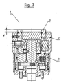
- Fig. 3 shows the longitudinal section according to Fig. 2 with a positive offset V.
- the display means 3 is shown relative to the adjusting cap device 2 in an extended position.
- a latching disc is formed on the underside of the adjusting cap device 2.
- This locking disc is formed with a predetermined number of holes at a predetermined distance from each other.
- the upper portion of the locking sleeve is formed as well as the lower portion of the locking sleeve cylindrical with a corresponding outer diameter.
- the top of the locking sleeve has spherical elevation or a spherical surface.
- the adjusting cap device 2 always remains in the lower, predetermined position.
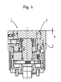
- Fig. 4 shows a further embodiment of the adjusting device 1 according to the invention in a longitudinal section.
- the adjusting device 1 differs from the adjusting device 1 according to Fig. 2 and 3 in that the second latching device 7 is designed differently. When it engages the Stellkappen Anlagen 2 moves and can only be solved by appropriate counter-movement from the locked position again. The exact operation is described below.
- Fig. 5 shows the longitudinal section of the adjusting device 1 according to Fig. 4 with a positive offset V, that is in an extended position.
- the display means 3 are extended relative to the actuating cap device 2, so that in each case the upper outer surfaces form an offset V to each other.
- a locking disk is arranged on the underside of the Stellkappen Anlagen 2, that is, the side which opposite to the display means 3, a locking disk.
- This locking disc is formed in a predetermined number of cut-outs formed as cut-out locking means at predefined intervals to each other. The distances are preferably equidistant.
- the adjusting cap device 2 is pressed by a biasing element designed as a compression spring in the direction of the coupling part.
- a locking sleeve corresponding to the detent sleeve, which is located below the detent disk, is pressed by a trained as a compression spring biasing member from below, that is, in the direction of the display means 3 against the locking disc.
- This second compression spring is slightly weaker than the first compression spring, which presses the locking disk down, formed, so that the adjusting cap means 2 remains in the lower position.
- the cylindrical locking sleeve has a flat surface at its upper end. If now the adjusting cap device 3 is rotated in such a way that one of the cutouts comes to lie exactly over the latching sleeve, the latching sleeve pushes into this cutout, so that the adjusting device 1 is locked or latched. In order now to solve this lock, the adjusting cap device 2 must be pulled up against the pressure of the first compression spring and rotated further.
- the adjusting cap device 2 After further rotation of the adjusting cap device 2 by a screening of the first latching device, or shortly by a click, the adjusting cap device 2 can be released without it snaps into place.
- the cutouts are no longer located exactly above the latching sleeve, whereby the latching sleeve is again pressed down against the second compression spring. The process is repeated when the Stellkappen issued 2 is further rotated and reach a further cut the locking sleeve.
- Fig. 6 shows a longitudinal section in the axial direction by the adjusting device. 1 Fig. 6 is essentially different from the Fig. 2 and Fig. 4 by the different design of the second locking device 7.
- the locking device 7 comprises a locking disk and a locking sleeve. Both, locking disk and latching sleeve have cooperating, corresponding latching means on each other.
- the locking means are at the locking sleeve formed as a two bevels formed tip (s).
- the locking means of the locking disc are formed as a corresponding recess (s), which receives the locking means of the locking sleeve.
- the adjusting device 1 is shown in a position in which the offset between the display means 3 and the adjusting cap means 2 is approximately zero, that is, the both outer, upper surfaces, those of the annular member formed as the indicating means 3 and the Stellkappen worn 2, approximately flush with each other are aligned.
- Fig. 7 shows the longitudinal section according to Fig. 6 with an offset V> zero.
- the offset V of the adjusting device 1 or between the adjusting cap device 2 and the display means 3 is different from zero, that is, the display means 3 is in an extended position, which is palpable by the operator even in the dark.
- a latching disc is formed on the underside of the adjusting cap device 2.
- This locking disc is formed with a certain number locking means at a predetermined distance and in a predetermined number.
- a corresponding, cooperating with the locking disc detent sleeve is formed.
- a lower part of this locking sleeve is formed with an anti-rotation, here in the form of a rectangular profile. This ensures that the locking sleeve can not rotate and only in an axial direction, that can be moved up and down.
- One or more biasing elements formed as a compression spring (s) press the detent sleeve up against the detent disk.
- the locking sleeve has in its upper part two slopes, which form a tip. If now the adjusting cap device 2 is rotated such that one of the detents of the detent disk comes to lie exactly over one of the detents of the detent sleeve, the detents and the upper end of the detent sleeve are exactly aligned with each other, which means that the detent sleeve moves into the screening of the detent disk , that is, the locking sleeve "clicks" into the locking disc. This "click” is clearly more tangible than the "clicks" of the first latch 5 alone.
- the adjusting cap device 2 always remains in the lower, predetermined position.
- display means 3 are provided, which preferably represents the number of misaligned revolutions.
- a relative to the adjusting cap means 2 adjustable ring element is provided, which makes the corresponding switching position recognizable depending on its position. This position can be, inter alia, flush with the upper side of the adjusting cap device 2, protruding out of the adjusting cap device 2 and projecting into the adjusting cap device 2.
- a display means 3 designed as an annular ring or more generally a ring-shaped element is arranged in a corresponding recess.
- the revolution ring is positioned via at least one threaded pin with pins which are set in oblique grooves on the circumference of the annular element.
- a switching device 6 designed as a cylindrical pin projection. This cooperates with a likewise belonging to the switching device 6 pendulum cylinder.
- the pendulum cylinder is designed to rotate about its axis. At the lower part of the pendulum cylinder is located on the underside of a groove. In the upper part of the pendulum cylinder protrudes from the upper end side of a cylindrical pin out, the axis of which is parallel and laterally offset, that is, eccentric to the axis of the pendulum cylinder. At the bottom of the pendulum cylinder, a groove is formed, which leads the pin, which protrudes from the top of the pendulum cylinder.
- the protruding from the annular element cylinder pin engages in the groove on the underside of the pendulum cylinder.
- the twisted Pendulum cylinder which changes the position of the protruding from the pendulum cylinder cylinder pin.
- the oblique grooves may be formed at the periphery of the annular member at different positions for two or more shift positions.
Landscapes
- Physics & Mathematics (AREA)
- Engineering & Computer Science (AREA)
- Optics & Photonics (AREA)
- General Engineering & Computer Science (AREA)
- General Physics & Mathematics (AREA)
- Automation & Control Theory (AREA)
- Telescopes (AREA)
- Prostheses (AREA)
- Aiming, Guidance, Guns With A Light Source, Armor, Camouflage, And Targets (AREA)
- Lock And Its Accessories (AREA)
- Casings For Electric Apparatus (AREA)
- Fittings On The Vehicle Exterior For Carrying Loads, And Devices For Holding Or Mounting Articles (AREA)
- Infusion, Injection, And Reservoir Apparatuses (AREA)
- Mechanical Control Devices (AREA)
Claims (17)
- Appareil de réglage (1) pour ajuster des composants qui peuvent être couplés à l'appareil de réglage (1), particulièrement pour régler le mécanisme de réticule d'une lunette de pointage, et comprenant : un dispositif capot de réglage (2) logé de manière tournante à un élément de couplage (4) pour opérer l'appareil de réglage (1), l'élément de couplage (4) étant formé pour transférer le mouvement du dispositif capot de réglage (2) à des composants qui peuvent être couplés à l'élément de couplage (4) pour ajuster ceux-ci, avec un premier dispositif de crantage (5) couplé au dispositif capot de réglage (2) et ayant des premiers moyens d'arrêt pour former un premier crantage, des moyens indicateurs (3) pour indiquer la rangée de la rotation du dispositif capot de réglage (2), et un mécanisme d'indexation (6) pour opérer les moyens indicateurs (3) selon une étendue prédéterminée du dispositif capot de réglage (2), caractérisé en ce qu'est prévu un deuxième dispositif de crantage (7) qui est couplé au dispositif capot de réglage (2) et qui montre un deuxième crantage formé par des deuxièmes moyens d'arrêt différents du premier crantage.
- Appareil de réglage (1) selon la Revendication 1, avec les moyens indicateurs (3) formés de manière amovible relativement au dispositif capot de réglage (2) et couplés au mécanisme d'indexation (6) tel que, à une première position d'indexation du mécanisme d'indexation (6), le moyen indicateur (3) prend une première position et qu'à une autre position d'indexation du mécanisme d'indexation (6) le moyen indicateur (3) est dans une position différente et palpable.
- Appareil de réglage (1) selon une des précédentes Revendications 1 à 2, caractérisé en ce que le deuxième dispositif de crantage (7) contient un premier élément de crantage et un deuxième élément de crantage concourant et correspondant avec ce premier, et qui sont formés pour être mis en prise.
- Appareil de réglage (1) selon une des précédentes Revendications 1 à 3, caractérisé en ce que le premier élément de crantage est un disque à crans.
- Appareil de réglage (1) selon une des précédentes Revendications 1 à 4, caractérisé en ce que le deuxième élément de crantage est une douille d'arrêt.
- Appareil de réglage (1) selon une des précédentes Revendications 1 à 5, caractérisé en ce que les moyens d'arrêt du premier élément de crantage sont formés comme un creux et/ou une élévation, et les moyens d'arrêt du deuxième élément de crantage comme leurs élévations et/ou creux correspondantes pour être mis en prise avec le premier moyen d'arrêt.
- Appareil de réglage (1) selon une des précédentes Revendications 1 à 6, caractérisé en ce que les moyens d'arrêt du deuxième élément de crantage sont formés comme des élévations sphériques et les moyens d'arrêt du premier élément de crantage correspondant comme des creux sphériques.
- Appareil de réglage (1) selon la Revendication 7, caractérisé en ce que le diamètre de l'élévation sphérique est plus grand que le diamètre du ceux sphérique.
- Appareil de réglage (1) selon une des précédentes Revendications 1 à 8, caractérisé en ce que le rapport du premier crantage avec le deuxième crantage est choisi de la fonction comprenant les rapports : 1 :2, 1 :5, 1 :10, 1 :20, 1 :25, 1 :50, 1 :100, 1 :125, 1 :150, 1 :200, 1 :250, 1 :500, 1 :750, 1 :1000, 1 :1250, 1 :1500, 1 :2000 ; 1 :2500, 1 :5000, 1 :7500, 1 :1000.
- Appareil de réglage (1) selon une des précédentes Revendications 1 à 9, caractérisé en ce que le deuxième dispositif de crantage (7) a en plus au moins un élément de prétension pour précontraindre les éléments de crantage l'un contre l'autre.
- Appareil de réglage (1) selon une des précédentes Revendications 1 à 10, caractérisée en ce que le deuxième dispositif de crantage (7) comprend deux éléments de prétension de forces de prétension agissant en sens inverse pour précontraindre les éléments de crantage l'un contre l'autre.
- Appareil de réglage (1) selon la Revendication 1, caractérisée en ce que les éléments de prétension sont munis de forces de prétension différentes.
- Appareil de réglage (1) selon une des précédentes Revendications 1 à 12, caractérisé en ce que le deuxième dispositif de crantage (7) a en plus une pièce de couplage décalable vers et/ou inverse à une direction effective de l'élément de prétension, et qui est arrangé entre un élément de crantage et le dispositif capot de réglage (2).
- Appareil de réglage (1) selon une des Revendications 11 ou 12, caractérisé en ce que
l'élément de prétension de la plus grande force de prétension est arrangé entre pièce de couplage et l'élément de crantage l'avoisinant. - Lunette de pointage avec un appareil de réglage (1) selon une des précédentes Revendications 1 à 14, avec une boîte tubulaire ayant des montures tubulaires pour un système oculaire et d'objectifs, aussi qu'un système d'inversion optique et un réticule conjuguant.
- Procédé à ajuster des composants couplés à un appareil de réglage (1) selon une des précédentes Revendications 1 à 14 par cet appareil de réglage (1) comprenant les pas suivants :mise au point fine de l'appareil de réglage (1) par la réaction palpable du premier dispositif de crantage,mise au point approximative de l'appareil de réglage (1) par la réaction palpable du deuxième dispositif de crantage,permettant aussi l'opération de ces pas dans l'ordre inverse.
- Procédé selon la Revendication 16, comprenant en plus le pas :Contrôle de la position de l'appareil de réglage (1) par des moyens indicateurs (3) selon une des précédentes Revendications 1 à 14, un tel contrôle étant opérable à chaque moment pendant le procédé.
Applications Claiming Priority (1)
| Application Number | Priority Date | Filing Date | Title |
|---|---|---|---|
| DE102006016834A DE102006016834A1 (de) | 2006-04-07 | 2006-04-07 | Stellvorrichtung |
Publications (4)
| Publication Number | Publication Date |
|---|---|
| EP1843122A2 EP1843122A2 (fr) | 2007-10-10 |
| EP1843122A3 EP1843122A3 (fr) | 2009-04-29 |
| EP1843122B1 true EP1843122B1 (fr) | 2010-08-25 |
| EP1843122B2 EP1843122B2 (fr) | 2020-02-19 |
Family
ID=38513489
Family Applications (1)
| Application Number | Title | Priority Date | Filing Date |
|---|---|---|---|
| EP07005733.6A Active EP1843122B2 (fr) | 2006-04-07 | 2007-03-21 | Dispositif de réglage |
Country Status (5)
| Country | Link |
|---|---|
| US (1) | US7612952B2 (fr) |
| EP (1) | EP1843122B2 (fr) |
| AT (1) | ATE479071T1 (fr) |
| DE (2) | DE102006016834A1 (fr) |
| ES (1) | ES2351519T3 (fr) |
Cited By (1)
| Publication number | Priority date | Publication date | Assignee | Title |
|---|---|---|---|---|
| EP3367044A1 (fr) | 2017-02-27 | 2018-08-29 | Swarovski-Optik KG. | Élément de réglage d'une ligne de visée d'un dispositif de visée optique ainsi que lunette de visée pourvue d'un tel élément de réglage et arme pourvue d'une telle lunette de visée ainsi que procédé de réglage de la ligne de visée |
Families Citing this family (44)
| Publication number | Priority date | Publication date | Assignee | Title |
|---|---|---|---|---|
| USRE46011E1 (en) | 2008-01-31 | 2016-05-24 | Lightforce Usa, Inc. | Locking adjustment dial mechanism for riflescope |
| CN101545741B (zh) * | 2008-03-26 | 2013-06-05 | 深圳市金凯进光电仪器有限公司 | 一种带有锁紧与调零及圈数标尺的调节手轮 |
| EP2304377A2 (fr) | 2008-06-22 | 2011-04-06 | Bernard Thomas Windauer | Bouton rotatif à butée sélectionnable par un opérateur |
| US8670179B2 (en) | 2008-12-08 | 2014-03-11 | Bernard T. Windauer | Multi-function turret knob |
| US8312667B2 (en) * | 2009-01-14 | 2012-11-20 | Premier Reticles, Ltd | Lockable adjustment mechanism |
| US7937879B2 (en) * | 2009-03-11 | 2011-05-10 | Sheltered Wings, Inc. | Rifle scope with a low-light visible element |
| US8166696B2 (en) | 2009-09-14 | 2012-05-01 | Sheltered Wings, Inc. | Rifle scope with adjustment stop |
| US8166697B1 (en) * | 2010-06-22 | 2012-05-01 | Sueskind Alan E | Rifle scope indicia system |
| DE102010061349B4 (de) * | 2010-12-20 | 2021-10-21 | Schmidt & Bender Gmbh & Co. Kg | Verstellturm für Zielfernrohre |
| US8490317B2 (en) | 2010-12-30 | 2013-07-23 | Trijicon, Inc. | Locking turret |
| DE102011013456B4 (de) | 2011-03-09 | 2017-10-26 | Carl Zeiss Optronics Gmbh | Verstelleinrichtung für ein Zielfernrohr |
| PH12013501818A1 (en) | 2011-03-10 | 2019-10-11 | Steiner Optik Gmbh | Adjusting device for adjusting the reticle unit of a telescopic sight |
| US9170068B2 (en) | 2012-01-04 | 2015-10-27 | Leupold & Stevens, Inc. | Locking adjustment device |
| TWI603116B (zh) | 2012-02-04 | 2017-10-21 | 伯里斯公司 | 具有投射對準點的光學裝置 |
| DE202012002286U1 (de) * | 2012-03-08 | 2013-06-10 | Carl Zeiss Sports Optics Gmbh | Betätigungselement für die Verstellung oder Einstellung eines Parameters eines optischen Geräts, insbesondere Absehenschnellverstellung für ein Zielfernrohr |
| US9677848B2 (en) | 2012-04-18 | 2017-06-13 | Sheltered Wings, Inc. | Multiple knob turret |
| US8919026B2 (en) | 2012-04-18 | 2014-12-30 | Sheltered Wings, Inc. | Rifle scope turret with spiral cam mechanism |
| US8806798B2 (en) * | 2012-11-21 | 2014-08-19 | Leupold & Stevens, Inc. | Riflescope adjustment knob with interchangeable adjustment indicator ring |
| WO2014145226A1 (fr) * | 2013-03-15 | 2014-09-18 | Huskemaw Optics, Llc | Système de tourelles à verrouillage mutuel |
| US10591253B1 (en) | 2013-03-15 | 2020-03-17 | Tangent Theta Inc. | Finger-adjustable scope adjustment mechanism |
| AT514321B1 (de) * | 2013-09-11 | 2014-12-15 | Swarovski Optik Kg | Verstellturm |
| AT514600B1 (de) * | 2013-09-11 | 2015-02-15 | Swarovski Optik Kg | Verstellturm |
| US9062934B1 (en) | 2013-12-04 | 2015-06-23 | Trijicon, Inc. | Locking adjuster |
| US9625235B2 (en) | 2014-03-28 | 2017-04-18 | Trijicon, Inc. | Relay assembly for optical sight |
| US10101122B2 (en) * | 2014-08-08 | 2018-10-16 | Revic, LLC | Rifle scope elevation turret mechanism |
| JP6411154B2 (ja) * | 2014-09-30 | 2018-10-24 | 京セラオプテック株式会社 | クリック機構 |
| US9423215B2 (en) * | 2014-11-26 | 2016-08-23 | Burris Corporation | Multi-turn elevation knob for optical device |
| CN104729360B (zh) * | 2015-02-11 | 2017-10-31 | 宁波舜宇电子有限公司 | 一种可更换快速校枪装置 |
| US10415934B2 (en) | 2015-02-27 | 2019-09-17 | Burris Company, Inc. | Self-aligning optical sight mount |
| US10443979B2 (en) * | 2016-01-15 | 2019-10-15 | Sig Sauer, Inc. | Turret assembly |
| US11105587B2 (en) | 2016-01-27 | 2021-08-31 | Sheltered Wings, Inc. | Turret with a zero stop |
| AU2017263555B2 (en) * | 2016-05-13 | 2019-07-18 | Revelyst Operations Llc | Adjustable zero-stop turret |
| AT518634B1 (de) * | 2016-12-01 | 2017-12-15 | Kahles Ges M B H | Verstellturm für eine fernoptische Einrichtung |
| AT518653B1 (de) | 2016-12-01 | 2017-12-15 | Kahles Ges M B H | Verstellturm für eine fernoptische Einrichtung |
| US11624586B2 (en) | 2017-02-22 | 2023-04-11 | Hensoldt Optronics Gmbh | Adjustment apparatus of a reticle device of a telescopic sight |
| CZ307280B6 (cs) * | 2017-06-06 | 2018-05-09 | Meopta - Optika, S.R.O. | Optický zaměřovač se zařízením pro indikaci otočky rektifikátoru a funkcí zerostop |
| US10900747B2 (en) * | 2017-08-25 | 2021-01-26 | Michael Ali Kilic | Turret for rifle scopes |
| DE102017129682A1 (de) * | 2017-12-12 | 2019-06-13 | Leica Camera Ag | Verstellturm |
| SE543936C2 (en) | 2018-09-12 | 2021-09-28 | Aimpoint Ab | Adjustable reflex sight |
| GB201900665D0 (en) | 2019-01-17 | 2019-03-06 | Deben Group Industries Ltd | 06557607002 |
| US11906268B2 (en) | 2019-02-27 | 2024-02-20 | Leupold & Stevens, Inc. | Tool-less re-zero adjustment knob for aiming devices, and methods of zeroing an aiming device |
| CN116235019A (zh) | 2020-06-16 | 2023-06-06 | 夏尔特银斯公司D.B.A.涡流光学 | 具有归零锁定的转台 |
| WO2024186547A1 (fr) | 2023-03-06 | 2024-09-12 | Leupold & Stevens, Inc. | Assemblage de bouton sans outil pour dispositif optique |
| US12235076B2 (en) | 2023-04-28 | 2025-02-25 | Leupold & Stevens, Inc. | Locking adjustment device |
Family Cites Families (11)
| Publication number | Priority date | Publication date | Assignee | Title |
|---|---|---|---|---|
| CH399251A (de) * | 1962-07-27 | 1966-03-31 | Lienhard Walter | Dioptervisier |
| DE1221336B (de) * | 1964-06-13 | 1966-07-21 | Busch Jaeger Duerener Metall | Rastwerk fuer elektrische Drehschalter |
| CH555587A (de) * | 1971-08-12 | 1974-10-31 | Ghielmetti Ag | Drehschalter mit mehreren arbeitsstellungen. |
| GB1539428A (en) * | 1976-04-05 | 1979-01-31 | Dynamic Controls Ltd | Indicators with rotary actuators |
| DE3208814C2 (de) | 1982-03-11 | 1985-04-18 | D. Swarovski & Co., Wattens, Tirol | Zielfernrohr |
| DE3737856A1 (de) | 1987-11-07 | 1989-05-18 | Zeiss Carl Fa | Gewehrzielfernrohr mit erweitertem verstellbereich |
| DE29720737U1 (de) * | 1997-11-22 | 1998-02-12 | Schmidt & Bender GmbH & Co KG Optisch-mechanische Werkstatt, 35444 Biebertal | Zielfernrohr |
| US6691447B1 (en) * | 2002-09-17 | 2004-02-17 | Leupold & Stevens, Inc. | Non-telescoping riflescope adjustment mechanism |
| DE10323544B4 (de) * | 2003-05-24 | 2005-10-27 | Preh Gmbh | Rasteinrichtung für ein dreheinstellbares, elektrisches Bauelement |
| TWI269860B (en) * | 2005-06-23 | 2007-01-01 | Asia Optical Co Inc | Collimator with night vision aiming mark |
| US7415791B2 (en) * | 2005-12-21 | 2008-08-26 | U.S. Optics, Inc. | Rifle scope with adjustment knob having multiple detent forces |
-
2006
- 2006-04-07 DE DE102006016834A patent/DE102006016834A1/de not_active Withdrawn
-
2007
- 2007-03-21 AT AT07005733T patent/ATE479071T1/de active
- 2007-03-21 EP EP07005733.6A patent/EP1843122B2/fr active Active
- 2007-03-21 ES ES07005733T patent/ES2351519T3/es active Active
- 2007-03-21 DE DE502007004832T patent/DE502007004832D1/de active Active
- 2007-04-05 US US11/783,018 patent/US7612952B2/en active Active
Cited By (1)
| Publication number | Priority date | Publication date | Assignee | Title |
|---|---|---|---|---|
| EP3367044A1 (fr) | 2017-02-27 | 2018-08-29 | Swarovski-Optik KG. | Élément de réglage d'une ligne de visée d'un dispositif de visée optique ainsi que lunette de visée pourvue d'un tel élément de réglage et arme pourvue d'une telle lunette de visée ainsi que procédé de réglage de la ligne de visée |
Also Published As
| Publication number | Publication date |
|---|---|
| ES2351519T3 (es) | 2011-02-07 |
| ATE479071T1 (de) | 2010-09-15 |
| DE502007004832D1 (de) | 2010-10-07 |
| DE102006016834A1 (de) | 2007-10-11 |
| US20080007843A1 (en) | 2008-01-10 |
| EP1843122B2 (fr) | 2020-02-19 |
| EP1843122A3 (fr) | 2009-04-29 |
| EP1843122A2 (fr) | 2007-10-10 |
| US7612952B2 (en) | 2009-11-03 |
Similar Documents
| Publication | Publication Date | Title |
|---|---|---|
| EP1843122B1 (fr) | Dispositif de réglage | |
| DE102010060343B4 (de) | Selbstarretierende Einstellvorrichtung | |
| EP2466245B1 (fr) | Dispositif de réglage pour systèmes optiques | |
| EP3190377B1 (fr) | Dispositif de réglage d'une lunette de visée et lunette de visée en étant équipée | |
| EP2314978B1 (fr) | Dispositif de réglage arrêtable pour le réglage d'un dispositif de visée | |
| EP1959221B1 (fr) | Elément d'actionnement | |
| EP2848888B1 (fr) | Tour de réglage avec mécanisme permettant la suppression du 'zero-stop' | |
| EP2848887B1 (fr) | Bouton de réglage avec indication du nombre de révolutions | |
| EP1855075B1 (fr) | Lunette de tir | |
| DE212013000042U1 (de) | Arretiereinstellvorrichtung | |
| DE102011013456B4 (de) | Verstelleinrichtung für ein Zielfernrohr | |
| DE202012002286U1 (de) | Betätigungselement für die Verstellung oder Einstellung eines Parameters eines optischen Geräts, insbesondere Absehenschnellverstellung für ein Zielfernrohr | |
| CH649377A5 (de) | Dioptervisier, insbesondere fuer sportgewehre. | |
| DE20301749U1 (de) | Stelleinrichtung und damit ausgestattetes Zielfernrohr | |
| DE202012012707U1 (de) | Vorrichtung zur Absehenschnellverstellung einer Visiereinrichtung | |
| EP3586078B1 (fr) | Dispositif de réglage pour un dispositif de visée d'une lunette de visée | |
| DE202025100452U1 (de) | Steuerknopf zur manuellen Feineinstellung von Einrichtung sowie Werkzeug für die Montage eines solchen Steuerknopfs | |
| WO2019114872A1 (fr) | Tourelle de réglage | |
| AT518653B1 (de) | Verstellturm für eine fernoptische Einrichtung | |
| EP3615881B1 (fr) | Dispositif permettant de régler un réticule | |
| AT521030B1 (de) | Stellturm zur Seitenverstellung einer Zielmarke eines Zielfernrohrs | |
| DE2063498C3 (fr) | ||
| DE102020113075A1 (de) | Zieleinrichtung für eine Handfeuerwaffe | |
| CH520385A (de) | Vorrichtung mit zwei Verstellmitteln |
Legal Events
| Date | Code | Title | Description |
|---|---|---|---|
| PUAI | Public reference made under article 153(3) epc to a published international application that has entered the european phase |
Free format text: ORIGINAL CODE: 0009012 |
|
| AK | Designated contracting states |
Kind code of ref document: A2 Designated state(s): AT BE BG CH CY CZ DE DK EE ES FI FR GB GR HU IE IS IT LI LT LU LV MC MT NL PL PT RO SE SI SK TR |
|
| AX | Request for extension of the european patent |
Extension state: AL BA HR MK YU |
|
| RIN1 | Information on inventor provided before grant (corrected) |
Inventor name: SCHAEFER, ANDREAS |
|
| PUAL | Search report despatched |
Free format text: ORIGINAL CODE: 0009013 |
|
| AK | Designated contracting states |
Kind code of ref document: A3 Designated state(s): AT BE BG CH CY CZ DE DK EE ES FI FR GB GR HU IE IS IT LI LT LU LV MC MT NL PL PT RO SE SI SK TR |
|
| AX | Request for extension of the european patent |
Extension state: AL BA HR MK RS |
|
| RIC1 | Information provided on ipc code assigned before grant |
Ipc: F41G 1/38 20060101AFI20070725BHEP Ipc: F41G 1/18 20060101ALI20090326BHEP |
|
| 17P | Request for examination filed |
Effective date: 20090813 |
|
| 17Q | First examination report despatched |
Effective date: 20090921 |
|
| AKX | Designation fees paid |
Designated state(s): AT BE BG CH CY CZ DE DK EE ES FI FR GB GR HU IE IS IT LI LT LU LV MC MT NL PL PT RO SE SI SK TR |
|
| GRAP | Despatch of communication of intention to grant a patent |
Free format text: ORIGINAL CODE: EPIDOSNIGR1 |
|
| GRAS | Grant fee paid |
Free format text: ORIGINAL CODE: EPIDOSNIGR3 |
|
| GRAA | (expected) grant |
Free format text: ORIGINAL CODE: 0009210 |
|
| AK | Designated contracting states |
Kind code of ref document: B1 Designated state(s): AT BE BG CH CY CZ DE DK EE ES FI FR GB GR HU IE IS IT LI LT LU LV MC MT NL PL PT RO SE SI SK TR |
|
| REG | Reference to a national code |
Ref country code: GB Ref legal event code: FG4D Free format text: NOT ENGLISH |
|
| REG | Reference to a national code |
Ref country code: CH Ref legal event code: EP |
|
| REG | Reference to a national code |
Ref country code: IE Ref legal event code: FG4D Free format text: LANGUAGE OF EP DOCUMENT: GERMAN |
|
| REF | Corresponds to: |
Ref document number: 502007004832 Country of ref document: DE Date of ref document: 20101007 Kind code of ref document: P |
|
| REG | Reference to a national code |
Ref country code: NL Ref legal event code: T3 |
|
| REG | Reference to a national code |
Ref country code: SE Ref legal event code: TRGR |
|
| LTIE | Lt: invalidation of european patent or patent extension |
Effective date: 20100825 |
|
| PG25 | Lapsed in a contracting state [announced via postgrant information from national office to epo] |
Ref country code: FI Free format text: LAPSE BECAUSE OF FAILURE TO SUBMIT A TRANSLATION OF THE DESCRIPTION OR TO PAY THE FEE WITHIN THE PRESCRIBED TIME-LIMIT Effective date: 20100825 Ref country code: LT Free format text: LAPSE BECAUSE OF FAILURE TO SUBMIT A TRANSLATION OF THE DESCRIPTION OR TO PAY THE FEE WITHIN THE PRESCRIBED TIME-LIMIT Effective date: 20100825 |
|
| REG | Reference to a national code |
Ref country code: ES Ref legal event code: FG2A Effective date: 20110126 |
|
| PG25 | Lapsed in a contracting state [announced via postgrant information from national office to epo] |
Ref country code: BG Free format text: LAPSE BECAUSE OF FAILURE TO SUBMIT A TRANSLATION OF THE DESCRIPTION OR TO PAY THE FEE WITHIN THE PRESCRIBED TIME-LIMIT Effective date: 20101125 Ref country code: PT Free format text: LAPSE BECAUSE OF FAILURE TO SUBMIT A TRANSLATION OF THE DESCRIPTION OR TO PAY THE FEE WITHIN THE PRESCRIBED TIME-LIMIT Effective date: 20101227 Ref country code: PL Free format text: LAPSE BECAUSE OF FAILURE TO SUBMIT A TRANSLATION OF THE DESCRIPTION OR TO PAY THE FEE WITHIN THE PRESCRIBED TIME-LIMIT Effective date: 20100825 Ref country code: IS Free format text: LAPSE BECAUSE OF FAILURE TO SUBMIT A TRANSLATION OF THE DESCRIPTION OR TO PAY THE FEE WITHIN THE PRESCRIBED TIME-LIMIT Effective date: 20101225 Ref country code: CY Free format text: LAPSE BECAUSE OF FAILURE TO SUBMIT A TRANSLATION OF THE DESCRIPTION OR TO PAY THE FEE WITHIN THE PRESCRIBED TIME-LIMIT Effective date: 20100825 Ref country code: SI Free format text: LAPSE BECAUSE OF FAILURE TO SUBMIT A TRANSLATION OF THE DESCRIPTION OR TO PAY THE FEE WITHIN THE PRESCRIBED TIME-LIMIT Effective date: 20100825 |
|
| REG | Reference to a national code |
Ref country code: IE Ref legal event code: FD4D |
|
| PG25 | Lapsed in a contracting state [announced via postgrant information from national office to epo] |
Ref country code: LV Free format text: LAPSE BECAUSE OF FAILURE TO SUBMIT A TRANSLATION OF THE DESCRIPTION OR TO PAY THE FEE WITHIN THE PRESCRIBED TIME-LIMIT Effective date: 20100825 Ref country code: GR Free format text: LAPSE BECAUSE OF FAILURE TO SUBMIT A TRANSLATION OF THE DESCRIPTION OR TO PAY THE FEE WITHIN THE PRESCRIBED TIME-LIMIT Effective date: 20101126 |
|
| PG25 | Lapsed in a contracting state [announced via postgrant information from national office to epo] |
Ref country code: DK Free format text: LAPSE BECAUSE OF FAILURE TO SUBMIT A TRANSLATION OF THE DESCRIPTION OR TO PAY THE FEE WITHIN THE PRESCRIBED TIME-LIMIT Effective date: 20100825 Ref country code: IE Free format text: LAPSE BECAUSE OF FAILURE TO SUBMIT A TRANSLATION OF THE DESCRIPTION OR TO PAY THE FEE WITHIN THE PRESCRIBED TIME-LIMIT Effective date: 20100825 |
|
| PLBI | Opposition filed |
Free format text: ORIGINAL CODE: 0009260 |
|
| PG25 | Lapsed in a contracting state [announced via postgrant information from national office to epo] |
Ref country code: RO Free format text: LAPSE BECAUSE OF FAILURE TO SUBMIT A TRANSLATION OF THE DESCRIPTION OR TO PAY THE FEE WITHIN THE PRESCRIBED TIME-LIMIT Effective date: 20100825 Ref country code: CZ Free format text: LAPSE BECAUSE OF FAILURE TO SUBMIT A TRANSLATION OF THE DESCRIPTION OR TO PAY THE FEE WITHIN THE PRESCRIBED TIME-LIMIT Effective date: 20100825 Ref country code: SK Free format text: LAPSE BECAUSE OF FAILURE TO SUBMIT A TRANSLATION OF THE DESCRIPTION OR TO PAY THE FEE WITHIN THE PRESCRIBED TIME-LIMIT Effective date: 20100825 Ref country code: EE Free format text: LAPSE BECAUSE OF FAILURE TO SUBMIT A TRANSLATION OF THE DESCRIPTION OR TO PAY THE FEE WITHIN THE PRESCRIBED TIME-LIMIT Effective date: 20100825 |
|
| PLAB | Opposition data, opponent's data or that of the opponent's representative modified |
Free format text: ORIGINAL CODE: 0009299OPPO |
|
| 26 | Opposition filed |
Opponent name: CARL ZEISS OPTRONICS GMBH Effective date: 20110514 |
|
| PLAX | Notice of opposition and request to file observation + time limit sent |
Free format text: ORIGINAL CODE: EPIDOSNOBS2 |
|
| R26 | Opposition filed (corrected) |
Opponent name: CARL ZEISS OPTRONICS GMBH Effective date: 20110514 |
|
| REG | Reference to a national code |
Ref country code: DE Ref legal event code: R026 Ref document number: 502007004832 Country of ref document: DE Effective date: 20110514 |
|
| PLBB | Reply of patent proprietor to notice(s) of opposition received |
Free format text: ORIGINAL CODE: EPIDOSNOBS3 |
|
| PG25 | Lapsed in a contracting state [announced via postgrant information from national office to epo] |
Ref country code: MT Free format text: LAPSE BECAUSE OF FAILURE TO SUBMIT A TRANSLATION OF THE DESCRIPTION OR TO PAY THE FEE WITHIN THE PRESCRIBED TIME-LIMIT Effective date: 20100825 |
|
| PLAB | Opposition data, opponent's data or that of the opponent's representative modified |
Free format text: ORIGINAL CODE: 0009299OPPO |
|
| R26 | Opposition filed (corrected) |
Opponent name: CARL ZEISS OPTRONICS GMBH Effective date: 20110514 |
|
| PLAB | Opposition data, opponent's data or that of the opponent's representative modified |
Free format text: ORIGINAL CODE: 0009299OPPO |
|
| R26 | Opposition filed (corrected) |
Opponent name: CASSIDIAN OPTRONICS GMBH Effective date: 20110514 |
|
| PLAB | Opposition data, opponent's data or that of the opponent's representative modified |
Free format text: ORIGINAL CODE: 0009299OPPO |
|
| R26 | Opposition filed (corrected) |
Opponent name: CASSIDIAN OPTRONICS GMBH Effective date: 20110514 |
|
| PG25 | Lapsed in a contracting state [announced via postgrant information from national office to epo] |
Ref country code: TR Free format text: LAPSE BECAUSE OF FAILURE TO SUBMIT A TRANSLATION OF THE DESCRIPTION OR TO PAY THE FEE WITHIN THE PRESCRIBED TIME-LIMIT Effective date: 20100825 |
|
| PG25 | Lapsed in a contracting state [announced via postgrant information from national office to epo] |
Ref country code: HU Free format text: LAPSE BECAUSE OF FAILURE TO SUBMIT A TRANSLATION OF THE DESCRIPTION OR TO PAY THE FEE WITHIN THE PRESCRIBED TIME-LIMIT Effective date: 20100825 |
|
| APBM | Appeal reference recorded |
Free format text: ORIGINAL CODE: EPIDOSNREFNO |
|
| APBP | Date of receipt of notice of appeal recorded |
Free format text: ORIGINAL CODE: EPIDOSNNOA2O |
|
| APAH | Appeal reference modified |
Free format text: ORIGINAL CODE: EPIDOSCREFNO |
|
| APBM | Appeal reference recorded |
Free format text: ORIGINAL CODE: EPIDOSNREFNO |
|
| APBP | Date of receipt of notice of appeal recorded |
Free format text: ORIGINAL CODE: EPIDOSNNOA2O |
|
| APBQ | Date of receipt of statement of grounds of appeal recorded |
Free format text: ORIGINAL CODE: EPIDOSNNOA3O |
|
| REG | Reference to a national code |
Ref country code: FR Ref legal event code: PLFP Year of fee payment: 10 |
|
| REG | Reference to a national code |
Ref country code: FR Ref legal event code: PLFP Year of fee payment: 11 |
|
| REG | Reference to a national code |
Ref country code: FR Ref legal event code: PLFP Year of fee payment: 12 |
|
| PGFP | Annual fee paid to national office [announced via postgrant information from national office to epo] |
Ref country code: GB Payment date: 20180329 Year of fee payment: 12 Ref country code: NL Payment date: 20180329 Year of fee payment: 12 Ref country code: LU Payment date: 20180329 Year of fee payment: 12 |
|
| PGFP | Annual fee paid to national office [announced via postgrant information from national office to epo] |
Ref country code: FR Payment date: 20180329 Year of fee payment: 12 Ref country code: SE Payment date: 20180329 Year of fee payment: 12 Ref country code: BE Payment date: 20180329 Year of fee payment: 12 Ref country code: MC Payment date: 20180328 Year of fee payment: 12 |
|
| PGFP | Annual fee paid to national office [announced via postgrant information from national office to epo] |
Ref country code: ES Payment date: 20180430 Year of fee payment: 12 Ref country code: CH Payment date: 20180419 Year of fee payment: 12 |
|
| PGFP | Annual fee paid to national office [announced via postgrant information from national office to epo] |
Ref country code: IT Payment date: 20180329 Year of fee payment: 12 |
|
| APBU | Appeal procedure closed |
Free format text: ORIGINAL CODE: EPIDOSNNOA9O |
|
| REG | Reference to a national code |
Ref country code: SE Ref legal event code: EUG |
|
| PG25 | Lapsed in a contracting state [announced via postgrant information from national office to epo] |
Ref country code: MC Free format text: LAPSE BECAUSE OF NON-PAYMENT OF DUE FEES Effective date: 20190401 Ref country code: SE Free format text: LAPSE BECAUSE OF NON-PAYMENT OF DUE FEES Effective date: 20190322 |
|
| REG | Reference to a national code |
Ref country code: CH Ref legal event code: PL |
|
| REG | Reference to a national code |
Ref country code: NL Ref legal event code: MM Effective date: 20190401 |
|
| GBPC | Gb: european patent ceased through non-payment of renewal fee |
Effective date: 20190321 |
|
| PG25 | Lapsed in a contracting state [announced via postgrant information from national office to epo] |
Ref country code: LU Free format text: LAPSE BECAUSE OF NON-PAYMENT OF DUE FEES Effective date: 20190321 |
|
| REG | Reference to a national code |
Ref country code: BE Ref legal event code: MM Effective date: 20190331 |
|
| PUAH | Patent maintained in amended form |
Free format text: ORIGINAL CODE: 0009272 |
|
| STAA | Information on the status of an ep patent application or granted ep patent |
Free format text: STATUS: PATENT MAINTAINED AS AMENDED |
|
| PG25 | Lapsed in a contracting state [announced via postgrant information from national office to epo] |
Ref country code: NL Free format text: LAPSE BECAUSE OF NON-PAYMENT OF DUE FEES Effective date: 20190401 Ref country code: GB Free format text: LAPSE BECAUSE OF NON-PAYMENT OF DUE FEES Effective date: 20190321 Ref country code: CH Free format text: LAPSE BECAUSE OF NON-PAYMENT OF DUE FEES Effective date: 20190331 Ref country code: LI Free format text: LAPSE BECAUSE OF NON-PAYMENT OF DUE FEES Effective date: 20190331 |
|
| 27A | Patent maintained in amended form |
Effective date: 20200219 |
|
| AK | Designated contracting states |
Kind code of ref document: B2 Designated state(s): AT BE BG CH CY CZ DE DK EE ES FI FR GB GR HU IE IS IT LI LT LU LV MC MT NL PL PT RO SE SI SK TR |
|
| REG | Reference to a national code |
Ref country code: DE Ref legal event code: R102 Ref document number: 502007004832 Country of ref document: DE |
|
| PG25 | Lapsed in a contracting state [announced via postgrant information from national office to epo] |
Ref country code: BE Free format text: LAPSE BECAUSE OF NON-PAYMENT OF DUE FEES Effective date: 20190331 Ref country code: FR Free format text: LAPSE BECAUSE OF NON-PAYMENT OF DUE FEES Effective date: 20190331 Ref country code: IT Free format text: LAPSE BECAUSE OF NON-PAYMENT OF DUE FEES Effective date: 20190321 |
|
| PG25 | Lapsed in a contracting state [announced via postgrant information from national office to epo] |
Ref country code: ES Free format text: LAPSE BECAUSE OF FAILURE TO SUBMIT A TRANSLATION OF THE DESCRIPTION OR TO PAY THE FEE WITHIN THE PRESCRIBED TIME-LIMIT Effective date: 20200219 |
|
| PGFP | Annual fee paid to national office [announced via postgrant information from national office to epo] |
Ref country code: DE Payment date: 20260331 Year of fee payment: 20 |
|
| PGFP | Annual fee paid to national office [announced via postgrant information from national office to epo] |
Ref country code: AT Payment date: 20260320 Year of fee payment: 20 |