EP1843405A2 - Système d'exploitation d'énergie à large bande et procédés associés - Google Patents
Système d'exploitation d'énergie à large bande et procédés associés Download PDFInfo
- Publication number
- EP1843405A2 EP1843405A2 EP07251472A EP07251472A EP1843405A2 EP 1843405 A2 EP1843405 A2 EP 1843405A2 EP 07251472 A EP07251472 A EP 07251472A EP 07251472 A EP07251472 A EP 07251472A EP 1843405 A2 EP1843405 A2 EP 1843405A2
- Authority
- EP
- European Patent Office
- Prior art keywords
- energy harvesting
- energy
- generators
- generator
- bandwidth
- Prior art date
- Legal status (The legal status is an assumption and is not a legal conclusion. Google has not performed a legal analysis and makes no representation as to the accuracy of the status listed.)
- Granted
Links
- 238000003306 harvesting Methods 0.000 title claims abstract description 156
- 238000000034 method Methods 0.000 title claims abstract description 20
- 238000012546 transfer Methods 0.000 claims abstract description 10
- 238000004891 communication Methods 0.000 claims abstract description 6
- 239000012858 resilient material Substances 0.000 claims abstract description 6
- 239000000463 material Substances 0.000 claims description 26
- 230000007613 environmental effect Effects 0.000 claims description 18
- 230000010355 oscillation Effects 0.000 claims description 10
- 229910001369 Brass Inorganic materials 0.000 claims description 6
- 239000010951 brass Substances 0.000 claims description 6
- 238000013016 damping Methods 0.000 claims description 4
- XAGFODPZIPBFFR-UHFFFAOYSA-N aluminium Chemical compound [Al] XAGFODPZIPBFFR-UHFFFAOYSA-N 0.000 claims description 3
- 229910052782 aluminium Inorganic materials 0.000 claims description 3
- 239000012530 fluid Substances 0.000 claims description 2
- 239000000203 mixture Substances 0.000 claims description 2
- 229920001296 polysiloxane Polymers 0.000 claims 1
- 230000036541 health Effects 0.000 description 13
- 238000012544 monitoring process Methods 0.000 description 10
- 238000010586 diagram Methods 0.000 description 6
- 230000003595 spectral effect Effects 0.000 description 6
- 230000004044 response Effects 0.000 description 5
- 238000013461 design Methods 0.000 description 4
- 230000005611 electricity Effects 0.000 description 4
- 230000008859 change Effects 0.000 description 3
- 239000004020 conductor Substances 0.000 description 3
- 230000002708 enhancing effect Effects 0.000 description 3
- 229910052710 silicon Inorganic materials 0.000 description 3
- 239000010703 silicon Substances 0.000 description 3
- PXHVJJICTQNCMI-UHFFFAOYSA-N Nickel Chemical compound [Ni] PXHVJJICTQNCMI-UHFFFAOYSA-N 0.000 description 2
- 230000000694 effects Effects 0.000 description 2
- -1 for example Substances 0.000 description 2
- 238000007689 inspection Methods 0.000 description 2
- HFGPZNIAWCZYJU-UHFFFAOYSA-N lead zirconate titanate Chemical compound [O-2].[O-2].[O-2].[O-2].[O-2].[Ti+4].[Zr+4].[Pb+2] HFGPZNIAWCZYJU-UHFFFAOYSA-N 0.000 description 2
- 239000000956 alloy Substances 0.000 description 1
- 229910045601 alloy Inorganic materials 0.000 description 1
- 239000003990 capacitor Substances 0.000 description 1
- 238000006243 chemical reaction Methods 0.000 description 1
- 238000006073 displacement reaction Methods 0.000 description 1
- 239000002305 electric material Substances 0.000 description 1
- 230000005284 excitation Effects 0.000 description 1
- 230000006872 improvement Effects 0.000 description 1
- 238000002955 isolation Methods 0.000 description 1
- 238000012423 maintenance Methods 0.000 description 1
- 238000005297 material degradation process Methods 0.000 description 1
- 238000012986 modification Methods 0.000 description 1
- 230000004048 modification Effects 0.000 description 1
- 229910052759 nickel Inorganic materials 0.000 description 1
- 230000000737 periodic effect Effects 0.000 description 1
- 230000008439 repair process Effects 0.000 description 1
- 238000001228 spectrum Methods 0.000 description 1
- 239000000126 substance Substances 0.000 description 1
- 239000013589 supplement Substances 0.000 description 1
Images


Classifications
-
- H—ELECTRICITY
- H02—GENERATION; CONVERSION OR DISTRIBUTION OF ELECTRIC POWER
- H02N—ELECTRIC MACHINES NOT OTHERWISE PROVIDED FOR
- H02N2/00—Electric machines in general using piezoelectric effect, electrostriction or magnetostriction
- H02N2/18—Electric machines in general using piezoelectric effect, electrostriction or magnetostriction producing electrical output from mechanical input, e.g. generators
- H02N2/186—Vibration harvesters
- H02N2/188—Vibration harvesters adapted for resonant operation
-
- H—ELECTRICITY
- H10—SEMICONDUCTOR DEVICES; ELECTRIC SOLID-STATE DEVICES NOT OTHERWISE PROVIDED FOR
- H10N—ELECTRIC SOLID-STATE DEVICES NOT OTHERWISE PROVIDED FOR
- H10N30/00—Piezoelectric or electrostrictive devices
- H10N30/30—Piezoelectric or electrostrictive devices with mechanical input and electrical output, e.g. functioning as generators or sensors
- H10N30/304—Beam type
- H10N30/306—Cantilevers
Definitions
- the present invention relates generally to energy harvesting systems. More specifically, the present invention relates to a broad band energy harvesting system and related methods to harvest energy from the structure.
- Various types of platforms such as, for example, aircraft structural components, aircraft skins, or other related components, when in operation are subjected to various environmental conditions such as stress and strain, exposure to temperature extremes, and significant vibration energy. Due to the various environmental conditions such components can suffer material degradation over time.
- Structural health monitoring helps promote realization of the full potential of such components.
- Remotely positioned sensors and/or nodes have been installed adjacent to such structures/components to monitor various parameters such as, for example, strain levels, stress, temperature, pressure, or vibration level to help manage physical inspection schedules, maintenance schedules, to help predict material failure, and generally monitor the "health" of such components.
- Such sensors have been provided a dedicated power supply such as power obtained through conductors, e.g., wires, connected to the aircraft electrical system or through chemical batteries.
- a dedicated power supply such as power obtained through conductors, e.g., wires, connected to the aircraft electrical system or through chemical batteries.
- Such wiring can, in some instances, undesirably result in increased weight and complexity of the component being monitored and/or the associated structure or component and are subject to damage or breakage requiring extensive repair costs and down time.
- batteries can be inappropriate due to their size. Batteries can also have a limited service life and therefore, typically require periodic inspection and/or replacement, are often positioned in locations difficult to reach, and often require costly disassembly and reassembly of the sensor or component to perform service on the battery. Further, batteries may not be suitable due to environmental constraints, i.e., temperature changes often affect battery performance.
- Other structural health monitoring systems include self-powered sensors attached to or embedded within the components to be monitored that can reduce dependence on batteries or any other external power source.
- the sensors can include an energy harvesting device either incorporated within the sensor or connected externally.
- Such sensors can be relatively small in size and can utilize, as a power source, energy obtained or otherwise transmitted through the component or structure being monitored. This type of sensor can typically consume very low amounts of power in the microwatt range.
- the energy harvesting devices for these sensors can generate small electrical currents, for example, when the material is deflected, such as when the monitored component vibrates.
- such devices typically include one or more cantilevered beams weighted with a proof mass on the free end and connected to a base on the opposite end, which is connected to or in direct contact with the vibrating structure.
- Each cantilevered beam can form a resonator or generator.
- Resonators and resonant systems have a natural frequency. Such resonators and resonant systems respond to frequencies close to their natural frequency much more intensely than to other frequencies.
- Each beam is sized and/or weighted to vibrate at a preselected resonant frequency coinciding with the expected frequency of the vibration energy generated by the structure.
- Such devices are designed with a relatively high quality factor and corresponding narrow bandwidth in order to maximize harvesting energy from the structure at the expected vibration frequency.
- This quality factor is a measure of the "quality" of the resonator, which in a mechanical system indicates, the effect of mechanical resistance to resonance--a high-quality factor equates to low mechanical resistance.
- Each beam also generally has a material attached which generates electrical currents when the beam, and thus the material, is deflected by the vibrations.
- Piezoelectric material is but one example of materials that perform this function. As each beam deflects at the preselected resonant frequency due to the vibrations generated by the structure, the piezoelectric material converts a fraction of the mechanical energy to electrical energy.
- An electric circuit including a storage device, such as a capacitor, is typically connected to the piezoelectric electric material to receive and store the generated electricity for use by the sensor or node.
- each of the beams or group of beams in a single energy harvesting device can be separately sized and/or weighted to vibrate at a separate preselected discrete resonant frequency coinciding with each of the discrete vibration frequencies expected to be generated by the structure.
- this multiple resonant frequency-multiple resonator design is configured so that each of the beams (resonators) are designed with a relatively high quality factor and correspondingly narrow bandwidth in order to maximize harvesting energy from the structure at the expected predetermined vibration frequencies.
- the sensors positioned in the areas of environmental energy having a frequency different than the expected frequency often do not receive sufficient power to provide continuous sensing capability necessary to perform even sampled sensing using a small duty cycle.
- the available energy distribution may change such that an area of the structure once having a high level of environmental energy at an expected frequency or frequencies is now subject only to a low-level of such energy at such frequency or frequencies, making power availability less reliable. In such situations, energy may nevertheless be available at one or multiple frequencies spaced over and/or shifting over different frequencies between a known frequency band.
- an operator installing the energy harvesting device may not know anything more than a range of potential frequencies that the energy harvesting device will have access to until immediately prior to actually installing the device in or on the vibrating structure, i.e., selecting the location on the structure to position the energy harvesting device.
- each individual energy harvesting device may need to be manually tuned according to its selected location, or groups of devices having different predetermined resonant frequencies may need to be manufactured separately for different portions of a structure expected to experience different but known vibration frequencies.
- energy harvesting devices having one or more discrete resonant frequencies configured to have a relatively high quality factor, and thus, a correspondingly relatively low bandwidth, may be unreliable in the expected frequency or frequencies of the environmentally generated vibration energy of the structure if the expected frequency or frequencies of the vibration energy do not fairly precisely match the actual frequency or frequencies of the environmentally generated vibration energy.
- a broad band energy harvesting system capable of harvesting energy over a relatively broad frequency band so that as the frequency of the environmentally generated energy shifts, the broad band energy harvesting system can continue harvesting energy, and thus, supply power to the associated sensor or sensors.
- the need for a single energy harvesting device or apparatus capable of working over a very broad range of frequencies that would be available in different locations on a structure.
- embodiments of the present invention advantageously provide a broad band energy harvesting system that reduces dependence on batteries or any other external power source.
- Embodiments of the present invention advantageously provide an energy harvesting system capable of generating or harvesting energy from a structure having environmental energy distributed over a wide frequency band.
- Embodiments of the present invention advantageously can also provide a single energy harvesting apparatus capable of working over a very broad range of frequencies, groups of which would be available in different locations on a structure.
- Embodiments of the present invention advantageously can additionally provide an energy harvesting apparatus capable of providing energy harvesting over multiple frequencies, simultaneously, within the wide frequency band.
- a broad band energy harvesting system includes a structure such as, for example, an aircraft having a body or portion thereof, e.g., leading-edge, a joint, or the skin of an aircraft wing.
- the structure can carry or otherwise conduct a plurality of environmentally produced vibration frequencies extending over a broad frequency range, which are generated by environmental factors interacting with the body of the structure.
- the system can also include a plurality of broadly tuned energy harvesting generators (resonators) each having a resonant frequency and configured to have a relatively low quality factor and corresponding relatively wide bandwidth covering a portion of the broad frequency range.
- the low quality factor and wide bandwidth allow each respective generator of the energy harvesting apparatus, in response to environmental energy emanating from the structure, to harvest a predefined minimum amount of energy from or at each of a plurality of discrete vibration frequencies adjacent the resonant frequency defining or otherwise falling within the bandwidth. That is, if energy or power is available from the structure at an associated minimum energy at one or more discrete vibration frequencies falling within the bandwidth of the respective generator, the energy harvesting apparatus can generate sufficient electric power to power an associated power consuming device such as, for example, a health monitoring sensor node.
- each generator can include or interface with a damper or other resistive means positioned to dampen or otherwise reduce the magnitude of the isolations of the respective generator.
- each of the plurality of energy harvesting generators of each energy harvesting apparatus collectively provide energy harvesting over the plurality of modes to thereby provide energy harvesting over a substantial portion of the broad frequency range. That is, according to an embodiment of the present invention, a maximum frequency for a first generator bandwidth of a first one of the plurality of generators can overlap a minimum frequency for a second generator bandwidth of a second one of the plurality of generators, and so on, to thereby provide energy harvesting capability at the predefined minimum amount of energy over a substantial portion of the frequency range.
- the energy harvesting apparatus includes a plurality of cantilevered beams each carrying a piezoelectric material to form a respective one of the plurality of generators.
- Each cantilevered beam is preferably fixedly connected to a common backbone.
- the common backbone includes a resilient material configured to allow the transfer of energy between adjacent generators to thereby enhance energy harvesting.
- Embodiments of the present invention can also include methods of harvesting energy from a structure.
- a method of harvesting energy from a structure can include providing an energy harvesting apparatus including a plurality of energy harvesting generators each connected to a non-fixed portion of a resilient common backbone and each adapted to oscillate at separate and distinct modes responsive to multifrequency environmental energy received from the structure.
- the method can include the steps of damping the oscillations of at least one but preferably each of the generators to simultaneously reduce the quality factor and widen the bandwidth of the generator to thereby provide energy harvesting capability at a predefined minimum amount of energy over a substantial portion of a relatively broad frequency range.
- the method can also include the step of selecting separate and distinct modes for each of the generators to collectively maximize the number of discrete frequencies within the broad frequency range capable of providing a predefined minimum energy. That is, the modes can be selected to increase the number of discrete vibration frequencies to enhance receiving energy or power that, when harvested, is sufficient to meet the needs of the associated power consuming device. Further, the method can also include the step of carrying part of the energy from one of the generators to an adjacent generator through the resilient backbone to thereby increase total energy harvested by each of the plurality of generators.
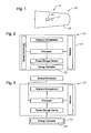
- FIG. 1 is a schematic diagram of a general system architecture of a broad band energy harvesting system according to an embodiment of the present invention
- FIG. 2 is a schematic diagram of a health monitoring sensor node having an energy harvesting apparatus housed therein according to an embodiment of the present invention
- FIG. 3 is a schematic diagram of a health monitoring sensor node connected to an externally positioned energy harvesting apparatus according to an embodiment of the present invention
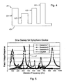
- FIG. 4 is a schematic diagram of a plurality of generators connected to a common backbone according to an embodiment of the present invention
- FIG. 5 is schematic of a spectral plot of a voltage frequency response for three generators along with a coupled response resulting from use of a resilient common backbone according to an embodiment of the present invention
- FIG. 6 is a schematic diagram of a generator connected to a base backbone according to an embodiment of the present invention.
- FIG. 7 is a schematic diagram of the generator illustrated in FIG. 6 modified with a damper according to an embodiment of the present invention
- FIG. 8 is a schematic of a combination spectral plot and energy-power consumption plot illustrating bandwidth coverage of four generators according to an embodiment of the present invention
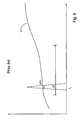
- FIG. 9 is a schematic of a combination spectral plot and energy-power consumption plot illustrating bandwidth coverage of a single prior art generator.
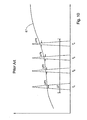
- FIG. 10 is a schematic of a combination spectral plot and energy-power consumption plot illustrating bandwidth coverage of four prior art generators.
- multi-node health monitoring sensor systems require power to perform their associated function.
- wireless structural health monitoring applications for example, where batteries are not appropriate due to their size, longevity, or environmental constraints, or when it is desired to supplement batteries with alternate energy sources to achieve long operating life, power or energy harvesting techniques are employed.
- energy harvesting relies on environmentally generated energy being available, energy harvesting devices or apparatus can be restricted or constrained to harvest energy according to predetermined parameters. Further, environmental energy distribution may change making energy harvesting less reliable than other forms of energy.
- embodiments of the present invention provide a broad band energy harvesting system, broad band energy harvesting apparatus, and methods of harvesting energy from a structure carrying environmentally induced energy.
- a broad band energy harvesting system 30 includes a structure 31 having a body 33 carrying environmentally produced energy, e.g., in the form of vibrations having one or more discrete frequencies distributed over a broad frequency range or band.
- body 33 can include the leading-edge, a joint, or the skin of an aircraft wing, an aircraft fuselage, various structural parts of other vehicles subject to environmental forces, and the support beams of stationery structures such as bridges, just to name a few.
- the system 30 also includes a plurality of energy harvesting apparatus 35 positioned either within (FIG. 2) or external to (FIG. 3) a power consuming device 37 such as, for example, a health monitoring sensor node positioned to monitor the health of the structure 31.
- Each energy harvesting apparatus 35 regardless of its relationship with the power consuming device 37, is positioned in vibration receiving communication with the body 33 structure 31.
- each energy harvesting apparatus 35 includes at least one but preferably a plurality of broadly tuned energy harvesting resonators or generators 39 (FIG. 4) positioned within, for example, the housing 41 (FIG. 2) of the power consuming device 37 or a separate housing 43 (FIG. 3) adapted to connect to a portion of the body 33 of the structure 31.
- the generators 39 are each connected to a base beam formed of a resilient material such as, for example, brass, silicon, or aluminum defining a resilient common backbone 45.
- FIG. 4 illustrates four generators 39 indicated as G 1 , G 2 , G 3 , G 4 connected to a resilient common backbone 45.
- the backbone 45 is preferably composed of brass or a brass alloy according to a preferred configuration. Where the backbone 45 is relatively small, such as when placed in or configured to form part of a microelectromechanical system (MEMS), the backbone 45 is preferably composed of silicon. Note, although brass, silicon, and aluminum are preferred materials, other materials which are resilient or can be made resilient are within the scope of the present invention.
- a portion of the common backbone 45 can be fixedly connected to the housing 41, 43, using means known and understood by those skilled in the art, so that a non-fixed portion extends therefrom.
- the common backbone 45 is preferably connected so that it is not substantially fixed in space, i.e., a relatively narrow percentage of the backbone 45 is connected to the housing 41, 43, at either a medial portion or at one of its ends in order to minimize damping of any vibrations being translated between individual generators 39.
- the backbone 45 can be connected directly to the body 33 of the structure without use of a housing 41, 43, as described above.
- the resilient common backbone 45 can form at least a portion of a resonator to further enhance energy transfer between adjacent generators 39.
- the resilient common backbone 45 can be configured to transfer or to allow the transfer of energy between adjacent energy harvesting generators 39 which may oscillate more efficiently at a different mode, thereby enhancing energy harvesting.
- FIG. 5 shows a voltage response for a three beam/generator arrangement, illustrating the edition of a coupled response 47 resulting from energy transfer between the three generators 39.
- the resilient common backbone 45 begins to bend and twist adding an order of different modes to the excitation of the cantilevers 49 forming the generators 39, generating voltage at frequencies not necessarily coinciding with the vibration frequencies emanating from the structure 31 or capable of being generated if a rigid common backbone were used.
- each generator 39 can include one or more cantilevered beams 49 each connected to the non-fixed portion of the resilient common backbone 45.
- Each cantilevered beam 49 includes an elongated shim 51 having any proximal end connected to the backbone 45 and a free distal end extending therefrom.
- the shim 51 preferably made of a conductive material such as, for example, brass, is interfaced with or otherwise in contact with a piezoelectric material 53, 55, such as, for example, lead zirconium titanate (PZT) to generate electricity.
- PZT lead zirconium titanate
- An electrode 57, 59 for example, made of nickel or other conductive material, is connected to or otherwise in contact with the piezoelectric material 53, 55, generally at a point of maximum strain in order to collect electrons generated by movement of the shim 51 and piezoelectric material 53, 55.
- a proof mass 61 or pair of proof masses 61 are positioned at the free distal end of the cantilevered beam 49.
- the proof mass or masses 61 generally configured so that the mass of the cantilevered beams 49 approximate that of the proof masses 61, can be used to set or refine the resonant frequency for each generator 39.
- a circuit is formed between the shim 51, piezoelectric material 53, and the first electrode 57.
- a circuit of opposite polarity is formed between the shim 51, piezoelectric material 55, and the first electrode 59.
- This configuration termed a bimorph, allows vibrations originating in the structure 31 to be transferred to the cantilevered beams 49 which resonate, for example, about different preselected frequencies, to provide a fairly steady stream of electricity both during a forward stroke and an aft stroke of the cantilevered beam 49.
- one or more of the cantilevered beams 49 can be connected to the resilient backbone 45 at a medial portion of the beam 49 rather than a proximal portion, as illustrated, however, in such configuration, the cantilevered beam 49 would generally be considered to be a pair of cantilevered beams 49 each connected at a proximal end forming a corresponding pair of resonators or generators 39.
- each energy harvesting generator 39 is configured with a preselected resonant frequency, e.g., f 1 , f 2 , f 3 , f 4 , corresponding to the generators G 1 , G 2 , G 3 , G 4 , respectively, illustrated in FIG. 4.
- a preselected resonant frequency e.g., f 1 , f 2 , f 3 , f 4 , corresponding to the generators G 1 , G 2 , G 3 , G 4 , respectively, illustrated in FIG. 4.
- Each defines a mode and functions to resonate at each of a plurality of frequencies adjacent the respective preselected resonant frequency f 1 , f 2 , f 3 , f 4 , defining a generator bandwidth ⁇ f 1 , ⁇ f 2 , ⁇ f 3 , ⁇ f 4 .
- the resonant frequency of each of the generators is a function of the geometry of the cantilevered beam 49 and the material composition of the shim 51 and/or piezoelectric material 53, 55, directly related to the stiffness of the cantilevered beam 49, and the mass of the cantilevered beam 49 which is typically controlled through use of the proof mass 61.
- the resonant frequency is equal to a constant times the square root of the stiffness of the cantilevered beam 49 divided by the mass of the beam 49.
- the piezoelectric material 53, 55 converts the mechanical energy into electrical energy.
- the generators collectively provide energy harvesting over each respective generator bandwidth ⁇ f 1 , ⁇ f 2 , ⁇ f 3 , ⁇ f 4 of the plurality of modes, to thereby provide energy harvesting capability over the broad frequency range ⁇ f sufficient to power the power consuming device 37.
- each generator 39 can be configured to have a relatively low quality factor and corresponding relatively wide bandwidth. That is, according to the preferred configuration, the energy harvesting generators 49 of each energy harvesting apparatus 39 can collectively provide energy harvesting over the multiple modes, e.g., having bandwidths ⁇ f 1 , ⁇ f 2 , ⁇ f 3 , ⁇ f 4 , respectively, to thereby provide energy harvesting over the broad frequency range ⁇ f or at least a substantial portion thereof.
- This can be a vast improvement over prior single- or multi- beam configurations having a high quality factor and relatively narrow bandwidth such as, for example, those illustrated in FIGS. 9 and 10, as it allows the energy harvesting apparatus 35 to function more versatility, providing energy harvesting capability to different portions of the structure 31 having environmental energy in the form of vibrations of different or variable/shifting frequencies.
- the vertical axis of the spectral plot in FIGS. 8-10 indicates either energy, power, or power density.
- the line 67 illustrated in the figures represent the energy level, power level, or power density from a vibration source having a discrete vibration frequency to supply sufficient power, for example, required by the preselected power consuming device 37 to sustain operations.
- each generator 39 by configuring each generator 39 to have a relatively low quality factor, the bandwidth can be correspondingly broadened to enhance the number or quantity of vibration frequencies potentially emanating from the structure 31 which can provide sufficient energy, power, or power density to power the power consuming device 37.
- the combination of the resonant frequencies, e.g., f 1 , f 2 , f 3 , f 4 , in the four generator example and the individual quality factors resulting in bandwidths ⁇ f 1 , ⁇ f 2 , ⁇ f 3 , ⁇ f 4 , can be selected to maximize the number of discrete frequencies within the broad frequency band ⁇ f capable of supplying sufficient energy, power, or power density.
- the maximum frequency for the first resonator bandwidth ⁇ f 1 can be substantially adjacent or overlap the minimum frequency for the second resonator bandwidth ⁇ f 2
- the maximum frequency for the second resonator bandwidth ⁇ f 2 can be substantially adjacent or overlap the minimum frequency for the third resonator bandwidth ⁇ f 3
- the maximum frequency for the third resonator bandwidth ⁇ f 3 can be substantially adjacent overlap the minimum frequency of the fourth resonator bandwidth ⁇ f 4 .
- the quality factor for a mechanical system is generally defined as a function of the resonant frequency divided by the frequency differential between the pair of frequencies identified along the frequency spectrum for each mode for the value of the associated spectral plot at half the maximum amplitude of the amplitude at the peak or resonant frequency, termed full width at half maximum.
- Prior energy harvesting systems tend to maximize performance of the sake of bandwidth, configuring their resonators to have a high quality factor of typically between 50 to 100 each centered about a preselected resonant frequency (see FIG. 9) or multiple preselected resonant frequency bands (see FIG. 10) expected to be emanating from the energy providing structure.
- the generators 39 are intentionally detuned to provide a low quality factor of less than 50, and more preferably less than approximately 10.
- each generator 39 can include a damper 71 or other form of resistive means known to those skilled in the art and positioned to reduce the magnitude of the oscillations of each of the generators 39 to thereby produce the relatively low quality factor and relatively wide resonator bandwidth.
- the damper 71 can include projections or ribs 73 extending from the shim 51, a fluid material (not shown) surrounding the cantilevered beam 49, a spring or piston (not shown) connected to the cantilevered beam 49, a combination friction pad (not shown) connected to a portion of the cantilevered beam 49 and a receiving surface connected to or part of the housing 41, 43, or structure 31, or any other means that inversely varies its effect with the time rate of change of displacement or velocity of the cantilevered beam 49.
- the lossy terms provided by the damper 71 can allow more efficient conversion of energy and electricity.
- Embodiments of the present invention also include methods of harvesting energy from a structure.
- a method of harvesting energy from a structure 31 can include providing an energy harvesting apparatus 35 including a plurality of energy harvesting resonators defining generators 39 each connected to a non-fixed portion of a resilient common backbone 45 (FIG. 4) and each adapted to oscillate at separate and distinct modes (FIG. 8) responsive to multifrequency environmental energy received from the structure 31.
- the method can also include the step of carrying part of the energy from one of the generators 39 to an adjacent generator 39 through the resilient backbone 45 to thereby increase total energy harvested by each of the plurality of generators 39 (see FIG. 5).
- the method can also include the step of selecting separate and distinct modes for each of the generators 39 to collectively maximize the number of discrete frequencies within a broad frequency range ⁇ f capable of providing a predefined minimum energy 67 (see FIG. 8). That is, the modes can be selected to increase the number of discrete vibration frequencies to enhance receiving energy or power that, when harvested, is sufficient to meet the needs of the power consuming device 37.
- the method can include damping the oscillations of at least one but preferably each of the generators 39 to simultaneously reduce the quality factor, for example, to at least below 50, but preferably below 10, and correspondingly widen the bandwidth of the generator 39 to thereby provide energy harvesting capability at a predefined minimum amount of energy over a substantial portion of the broad frequency range ⁇ f.
- Embodiments of the present invention provide a sequence of resonators/generators each covering a portion of a frequency range used to cover a broad frequency range.
- each one of these generators can be designed to resonate at a separate frequency within the wide frequency band and with an intentionally low quality factor, enhancing the overall energy output of the energy harvesting apparatus over that which could be achieved with a conventional resonator especially where the environmental vibration energy is at a frequency different than the generator resonant frequency.
- these generators can be connected in tandem to provide necessary power over the complete broad frequency range. As such, the operation of this apparatus can be compared to that of a xylophone, with each one of the generators corresponding to a broadly tuned resonant member of the xylophone.
- the generators are obtained using a cantilevered beam, fixed at one end, and covered with a piezoelectric material.
- Such cantilevered beams can be connected to a resilient backbone which can allow energy from one beam to be transmitted to another beam which can more efficiently utilize such energy thereby enhancing the overall energy output of the energy harvesting apparatus over that which could be achieved otherwise.
- These cantilevers can also be coated with piezoelectric material such as lead zirconium titanate (PZT) to obtain a voltage that is proportional to the strain on the cantilever. Appropriate and differing proof masses can be used at the end of these cantilevers to better further tune the individual structures.
- PZT lead zirconium titanate
- the piezoelectric material can further be used on opposite sides of the cantilever to obtain a bimorph, further doubling the voltage or the power that can be harvested.
- the broad band energy harvesting system can be part of a broader health monitoring system such as that described in, for example, U.S. Patent Application No. 11/286,792 by Andarawis et al.
Landscapes
- General Electrical Machinery Utilizing Piezoelectricity, Electrostriction Or Magnetostriction (AREA)
- Other Liquid Machine Or Engine Such As Wave Power Use (AREA)
Applications Claiming Priority (1)
| Application Number | Priority Date | Filing Date | Title |
|---|---|---|---|
| US11/398,840 US7667375B2 (en) | 2006-04-06 | 2006-04-06 | Broad band energy harvesting system and related methods |
Publications (3)
| Publication Number | Publication Date |
|---|---|
| EP1843405A2 true EP1843405A2 (fr) | 2007-10-10 |
| EP1843405A3 EP1843405A3 (fr) | 2009-11-18 |
| EP1843405B1 EP1843405B1 (fr) | 2011-06-08 |
Family
ID=38326132
Family Applications (1)
| Application Number | Title | Priority Date | Filing Date |
|---|---|---|---|
| EP07251472A Ceased EP1843405B1 (fr) | 2006-04-06 | 2007-04-03 | Système d'exploitation d'énergie à large bande et procédés associés |
Country Status (2)
| Country | Link |
|---|---|
| US (1) | US7667375B2 (fr) |
| EP (1) | EP1843405B1 (fr) |
Cited By (7)
| Publication number | Priority date | Publication date | Assignee | Title |
|---|---|---|---|---|
| WO2009046709A1 (fr) * | 2007-10-12 | 2009-04-16 | Eads Deutschland Gmbh | Microgénérateur piézoélectrique |
| WO2010080234A3 (fr) * | 2009-01-09 | 2010-09-10 | The Boeing Company | Unité autonome de génération d'énergie électrique pour un système auxiliaire sur une plateforme aéroportée |
| US8080920B2 (en) | 2007-03-21 | 2011-12-20 | The University Of Vermont And State Agricultural College | Piezoelectric vibrational energy harvesting systems incorporating parametric bending mode energy harvesting |
| WO2012094041A1 (fr) * | 2011-01-03 | 2012-07-12 | The Boeing Company | Systèmes et procédés de récolte d'énergie de vibration de véhicules |
| CN113514719A (zh) * | 2021-06-02 | 2021-10-19 | 国能大渡河检修安装有限公司 | 磁致振动压电结合摩擦电的能量收集测试系统及其方法 |
| CN115387963A (zh) * | 2022-07-12 | 2022-11-25 | 郑州大学 | 飞机机翼振动及风能复合收集装置 |
| IT202100027965A1 (it) * | 2021-11-03 | 2023-05-03 | Milano Politecnico | Dispositivo multi-risonatore per uso in sistemi di raccolta energia o in un sistema di azionamento |
Families Citing this family (34)
| Publication number | Priority date | Publication date | Assignee | Title |
|---|---|---|---|---|
| JP4142738B2 (ja) * | 2006-11-01 | 2008-09-03 | 松下電器産業株式会社 | 圧電型発電機構 |
| US8948870B2 (en) * | 2008-09-09 | 2015-02-03 | Incube Labs, Llc | Energy harvesting mechanism |
| US9026212B2 (en) | 2008-09-23 | 2015-05-05 | Incube Labs, Llc | Energy harvesting mechanism for medical devices |
| US20100301706A1 (en) * | 2009-05-27 | 2010-12-02 | Freescale Semiconductor, Inc. | Differential piezoelectric sensor |
| JP2012533275A (ja) | 2009-07-10 | 2012-12-20 | ヴァイキング エーティー,エルエルシー | 取り付け可能な腕部を有するスマートアクチュエータ装置及びエネルギー取得装置 |
| WO2011006028A2 (fr) | 2009-07-10 | 2011-01-13 | Viking At, Llc | Actionneur en matériau intelligent à petite échelle et appareil de collecte dénergie |
| JP2013504299A (ja) | 2009-09-04 | 2013-02-04 | ヴァイキング エーティー,エルエルシー | 共振動作に適合されるスマート材料アクチュエータ |
| US20110109102A1 (en) * | 2009-10-29 | 2011-05-12 | Mccoy John J | Meta-material vibration energy harvester |
| US7986076B2 (en) * | 2009-11-02 | 2011-07-26 | Toyota Motor Engineering & Manufacturing North America, Inc, | Energy harvesting device |
| KR101295670B1 (ko) * | 2009-12-11 | 2013-08-14 | 한국전자통신연구원 | 압전 발전기 |
| US8850892B2 (en) | 2010-02-17 | 2014-10-07 | Viking At, Llc | Smart material actuator with enclosed compensator |
| EP2545652B1 (fr) | 2010-03-12 | 2018-02-28 | Sunrise Micro Devices Inc. | Communications peu consommatrices d'énergie |
| US7936109B1 (en) * | 2010-03-31 | 2011-05-03 | Hong Kong Applied Science And Technology Research Institute Co. Ltd. | Non-resonant energy harvesting devices and methods |
| TW201221091A (en) | 2010-04-23 | 2012-06-01 | Access Business Group Int Llc | Energy harvesting seating |
| JP2014504135A (ja) | 2010-12-09 | 2014-02-13 | ヴァイキング エーティー,エルエルシー | 第2ステージを持つ高速スマート材料アクチュエータ |
| US11001494B2 (en) | 2011-06-23 | 2021-05-11 | Duality Reality Energy, LLC | Multi-zone microstructure spring |
| US9085454B2 (en) | 2011-07-05 | 2015-07-21 | Duality Reality Energy, LLC | Reduced stiffness micro-mechanical structure |
| US10139505B2 (en) | 2011-08-09 | 2018-11-27 | Pgs Geophysical As | Digital sensor streamers and applications thereof |
| US8650963B2 (en) | 2011-08-15 | 2014-02-18 | Pgs Geophysical As | Electrostatically coupled pressure sensor |
| US8717845B2 (en) | 2011-08-24 | 2014-05-06 | Pgs Geophysical As | Quality-based steering methods and systems for 4D geophysical surveys |
| US9076961B2 (en) * | 2012-01-31 | 2015-07-07 | Duality Reality Energy, LLC | Energy harvesting with a micro-electro-machanical system (MEMS) |
| US9059628B2 (en) | 2012-02-22 | 2015-06-16 | International Electronic Machines Corp. | Energy harvesting |
| US8866316B2 (en) | 2012-06-21 | 2014-10-21 | General Electric Company | Tunable vibration energy harvester and method |
| US20140373622A1 (en) * | 2013-06-21 | 2014-12-25 | Simmonds Precision Products, Inc. | Wireless fuel sensor |
| US10276776B2 (en) | 2013-12-24 | 2019-04-30 | Viking At, Llc | Mechanically amplified smart material actuator utilizing layered web assembly |
| US9786832B2 (en) | 2015-01-05 | 2017-10-10 | Samsung Electronics Co., Ltd. | Energy harvester |
| EP3295554B1 (fr) | 2015-05-11 | 2019-04-24 | Yeditepe Universitesi | Dispositif de collecte d'énergie de vibration |
| US11012006B2 (en) | 2015-10-19 | 2021-05-18 | Massachusetts Institute Of Technology | Micro electromechanical system (MEMS) energy harvester with residual stress induced instability |
| JP2019503722A (ja) | 2015-11-17 | 2019-02-14 | インスパイア・メディカル・システムズ・インコーポレイテッドInspire Medical Systems, Inc. | 睡眠呼吸障害(sdb)微小刺激治療装置 |
| US10243136B2 (en) * | 2016-08-22 | 2019-03-26 | Masoud Ghanbari | Piezoelectric energy harvesting system from vehicle's tires |
| KR102715031B1 (ko) * | 2016-10-05 | 2024-10-10 | 삼성전자주식회사 | 공진기를 포함하는 필터 시스템 |
| US10694466B2 (en) | 2017-06-20 | 2020-06-23 | University Of South Carolina | Power optimization for a unit cell metamaterial energy harvester |
| CN108860215A (zh) * | 2018-09-12 | 2018-11-23 | 湖南磁浮技术研究中心有限公司 | 一种中低速磁浮轨道振动衰减与感应装置 |
| US12546378B2 (en) | 2025-09-11 | 2026-02-10 | Xingzhuang Zhao | Coupled-beam energy harvesting damper |
Family Cites Families (9)
| Publication number | Priority date | Publication date | Assignee | Title |
|---|---|---|---|---|
| US5814921A (en) * | 1995-03-13 | 1998-09-29 | Ocean Power Technologies, Inc. | Frequency multiplying piezoelectric generators |
| US5856722A (en) * | 1996-01-02 | 1999-01-05 | Cornell Research Foundation, Inc. | Microelectromechanics-based frequency signature sensor |
| AU7382200A (en) * | 1999-09-16 | 2001-04-17 | Ut-Battelle, Llc | Piezoelectric power generator |
| US6771007B2 (en) * | 2002-04-17 | 2004-08-03 | The Boeing Company | Vibration induced perpetual energy resource |
| US6858970B2 (en) * | 2002-10-21 | 2005-02-22 | The Boeing Company | Multi-frequency piezoelectric energy harvester |
| US7579757B2 (en) * | 2004-01-21 | 2009-08-25 | The Regents Of The University Of Michigan | Method and micro power generator for generating electrical power from low frequency vibrational energy |
| US7785001B2 (en) * | 2004-05-10 | 2010-08-31 | Arizona Board Of Regents | Apparatus and method for sensing change in environmental conditions |
| US7409851B2 (en) * | 2005-03-29 | 2008-08-12 | Cornell Research Foundation, Inc. | Detection of small bound mass |
| US20070125176A1 (en) * | 2005-12-02 | 2007-06-07 | Honeywell International, Inc. | Energy harvesting device and methods |
-
2006
- 2006-04-06 US US11/398,840 patent/US7667375B2/en active Active
-
2007
- 2007-04-03 EP EP07251472A patent/EP1843405B1/fr not_active Ceased
Cited By (15)
| Publication number | Priority date | Publication date | Assignee | Title |
|---|---|---|---|---|
| US8080920B2 (en) | 2007-03-21 | 2011-12-20 | The University Of Vermont And State Agricultural College | Piezoelectric vibrational energy harvesting systems incorporating parametric bending mode energy harvesting |
| WO2009046709A1 (fr) * | 2007-10-12 | 2009-04-16 | Eads Deutschland Gmbh | Microgénérateur piézoélectrique |
| US8232706B2 (en) | 2009-01-09 | 2012-07-31 | The Boeing Company | Autonomous power generation unit for auxiliary system on an airborne platform |
| WO2010080234A3 (fr) * | 2009-01-09 | 2010-09-10 | The Boeing Company | Unité autonome de génération d'énergie électrique pour un système auxiliaire sur une plateforme aéroportée |
| JP2014502836A (ja) * | 2011-01-03 | 2014-02-03 | ザ・ボーイング・カンパニー | 乗物に由来する振動エネルギーを集積するためのシステムおよび方法 |
| CN103314520A (zh) * | 2011-01-03 | 2013-09-18 | 波音公司 | 收集交通工具振动能量的系统和方法 |
| WO2012094041A1 (fr) * | 2011-01-03 | 2012-07-12 | The Boeing Company | Systèmes et procédés de récolte d'énergie de vibration de véhicules |
| US8860234B2 (en) | 2011-01-03 | 2014-10-14 | The Boeing Company | Systems and methods for harvesting vibrational energy from vehicles |
| CN103314520B (zh) * | 2011-01-03 | 2016-06-01 | 波音公司 | 收集交通工具振动能量的系统和方法 |
| CN113514719A (zh) * | 2021-06-02 | 2021-10-19 | 国能大渡河检修安装有限公司 | 磁致振动压电结合摩擦电的能量收集测试系统及其方法 |
| CN113514719B (zh) * | 2021-06-02 | 2024-03-29 | 国能大渡河检修安装有限公司 | 磁致振动压电结合摩擦电的能量收集测试系统及其方法 |
| IT202100027965A1 (it) * | 2021-11-03 | 2023-05-03 | Milano Politecnico | Dispositivo multi-risonatore per uso in sistemi di raccolta energia o in un sistema di azionamento |
| WO2023079410A1 (fr) * | 2021-11-03 | 2023-05-11 | Politecnico Di Milano | Dispositif à multiples résonateurs piézoélectriques pour la récupération d'énergie ou l'actionnement |
| CN115387963A (zh) * | 2022-07-12 | 2022-11-25 | 郑州大学 | 飞机机翼振动及风能复合收集装置 |
| CN115387963B (zh) * | 2022-07-12 | 2024-06-04 | 郑州大学 | 飞机机翼振动及风能复合收集装置 |
Also Published As
| Publication number | Publication date |
|---|---|
| US20090167110A1 (en) | 2009-07-02 |
| US7667375B2 (en) | 2010-02-23 |
| EP1843405A3 (fr) | 2009-11-18 |
| EP1843405B1 (fr) | 2011-06-08 |
Similar Documents
| Publication | Publication Date | Title |
|---|---|---|
| EP1843405B1 (fr) | Système d'exploitation d'énergie à large bande et procédés associés | |
| EP1869754B1 (fr) | Procede permettant de transformer de l'energie vibratoire mecanique en energie electrique | |
| Xue et al. | Broadband piezoelectric energy harvesting devices using multiple bimorphs with different operating frequencies | |
| US12101041B2 (en) | Self-powered sensor nodes for structural health monitoring | |
| US20210399203A1 (en) | Metamaterial-Based Substrate for Piezoelectric Energy Harvesters | |
| US20080277941A1 (en) | Generation of Electrical Power From Fluid Flows | |
| US7884490B1 (en) | Resonating blade for electric power generation | |
| CN101449450A (zh) | 用于将机械振动能转化为电能的机电发电机和方法 | |
| JP2009509495A (ja) | 周波整流を使用するエネルギーハーベスティング | |
| US7936109B1 (en) | Non-resonant energy harvesting devices and methods | |
| JP2010517285A (ja) | 電圧を発生させるための自給式圧電デバイス | |
| EP2494689A2 (fr) | Oscillateur non linéaire pour la collecte d'une énergie de vibration | |
| EP2983287A1 (fr) | Collecteur d'énergie | |
| US8970092B2 (en) | Electricity generator having recovery of energy from mechanical vibrations | |
| JPH07245970A (ja) | 圧電素子発電装置 | |
| KR101713798B1 (ko) | 광대역 압전 에너지 하베스터 | |
| EP2922107B1 (fr) | Appareil de collecte d'énergie | |
| Ostaševičius et al. | Investigation of energy harvesting from high frequency cutting tool vibrations | |
| KR101652815B1 (ko) | 캔틸레버 및 이를 이용한 에너지 하베스터 | |
| Iannacci et al. | Up-scaled macro-device implementation of a MEMS wideband vibration piezoelectric energy harvester design concept | |
| Flicker et al. | Validation of optimised vibration energy harvesters under near operational conditions | |
| Gratuze et al. | A multi-mode non-linear acoustic piezoelectric MEMS energy harvester | |
| Gljušćić | Miniaturized wearable broadband energy harvesters | |
| KR20200010820A (ko) | 압전 에너지 하베스팅을 이용한 고장 예지 방법 | |
| Ueno et al. | Enhanced acceleration transmission via dual-beam frequency conversion interposer for design-flexible MEMS vibration energy harvesters |
Legal Events
| Date | Code | Title | Description |
|---|---|---|---|
| PUAI | Public reference made under article 153(3) epc to a published international application that has entered the european phase |
Free format text: ORIGINAL CODE: 0009012 |
|
| AK | Designated contracting states |
Kind code of ref document: A2 Designated state(s): AT BE BG CH CY CZ DE DK EE ES FI FR GB GR HU IE IS IT LI LT LU LV MC MT NL PL PT RO SE SI SK TR |
|
| AX | Request for extension of the european patent |
Extension state: AL BA HR MK YU |
|
| 17P | Request for examination filed |
Effective date: 20080327 |
|
| PUAL | Search report despatched |
Free format text: ORIGINAL CODE: 0009013 |
|
| AK | Designated contracting states |
Kind code of ref document: A3 Designated state(s): AT BE BG CH CY CZ DE DK EE ES FI FR GB GR HU IE IS IT LI LT LU LV MC MT NL PL PT RO SE SI SK TR |
|
| AX | Request for extension of the european patent |
Extension state: AL BA HR MK RS |
|
| AKX | Designation fees paid |
Designated state(s): DE FR GB IT |
|
| RIN1 | Information on inventor provided before grant (corrected) |
Inventor name: DELGADO, ELADIO, CLEMENTE Inventor name: WOJNAROWSKI, ROBERT, JOHN Inventor name: ANDARAWIS, EMAD, ANDARAWIS Inventor name: RAO, SAMANTHA Inventor name: BERKAN, ERTUGRUL |
|
| GRAP | Despatch of communication of intention to grant a patent |
Free format text: ORIGINAL CODE: EPIDOSNIGR1 |
|
| GRAS | Grant fee paid |
Free format text: ORIGINAL CODE: EPIDOSNIGR3 |
|
| RIN1 | Information on inventor provided before grant (corrected) |
Inventor name: RAO, SAMANTHA Inventor name: BERKAN, ERTUGRUL Inventor name: DELGADO, ELADIO, CLEMENTE Inventor name: WOJNAROWSKI, ROBERT, JOHN Inventor name: ANDARAWIS, EMAD, ANDARAWIS |
|
| GRAA | (expected) grant |
Free format text: ORIGINAL CODE: 0009210 |
|
| AK | Designated contracting states |
Kind code of ref document: B1 Designated state(s): DE FR GB IT |
|
| REG | Reference to a national code |
Ref country code: GB Ref legal event code: FG4D |
|
| REG | Reference to a national code |
Ref country code: DE Ref legal event code: R096 Ref document number: 602007015013 Country of ref document: DE Effective date: 20110721 |
|
| PLBE | No opposition filed within time limit |
Free format text: ORIGINAL CODE: 0009261 |
|
| STAA | Information on the status of an ep patent application or granted ep patent |
Free format text: STATUS: NO OPPOSITION FILED WITHIN TIME LIMIT |
|
| 26N | No opposition filed |
Effective date: 20120309 |
|
| REG | Reference to a national code |
Ref country code: DE Ref legal event code: R097 Ref document number: 602007015013 Country of ref document: DE Effective date: 20120309 |
|
| REG | Reference to a national code |
Ref country code: FR Ref legal event code: PLFP Year of fee payment: 10 |
|
| REG | Reference to a national code |
Ref country code: FR Ref legal event code: PLFP Year of fee payment: 11 |
|
| REG | Reference to a national code |
Ref country code: FR Ref legal event code: PLFP Year of fee payment: 12 |
|
| PGFP | Annual fee paid to national office [announced via postgrant information from national office to epo] |
Ref country code: DE Payment date: 20180427 Year of fee payment: 12 |
|
| PGFP | Annual fee paid to national office [announced via postgrant information from national office to epo] |
Ref country code: FR Payment date: 20180425 Year of fee payment: 12 Ref country code: IT Payment date: 20180423 Year of fee payment: 12 |
|
| PGFP | Annual fee paid to national office [announced via postgrant information from national office to epo] |
Ref country code: GB Payment date: 20180427 Year of fee payment: 12 |
|
| REG | Reference to a national code |
Ref country code: DE Ref legal event code: R119 Ref document number: 602007015013 Country of ref document: DE |
|
| GBPC | Gb: european patent ceased through non-payment of renewal fee |
Effective date: 20190403 |
|
| PG25 | Lapsed in a contracting state [announced via postgrant information from national office to epo] |
Ref country code: GB Free format text: LAPSE BECAUSE OF NON-PAYMENT OF DUE FEES Effective date: 20190403 Ref country code: DE Free format text: LAPSE BECAUSE OF NON-PAYMENT OF DUE FEES Effective date: 20191101 |
|
| PG25 | Lapsed in a contracting state [announced via postgrant information from national office to epo] |
Ref country code: FR Free format text: LAPSE BECAUSE OF NON-PAYMENT OF DUE FEES Effective date: 20190430 |
|
| PG25 | Lapsed in a contracting state [announced via postgrant information from national office to epo] |
Ref country code: IT Free format text: LAPSE BECAUSE OF NON-PAYMENT OF DUE FEES Effective date: 20190403 |