EP1843438A2 - Éliminateur statique à entretien nul - Google Patents
Éliminateur statique à entretien nul Download PDFInfo
- Publication number
- EP1843438A2 EP1843438A2 EP07005515A EP07005515A EP1843438A2 EP 1843438 A2 EP1843438 A2 EP 1843438A2 EP 07005515 A EP07005515 A EP 07005515A EP 07005515 A EP07005515 A EP 07005515A EP 1843438 A2 EP1843438 A2 EP 1843438A2
- Authority
- EP
- European Patent Office
- Prior art keywords
- static eliminator
- hollow cylinder
- cleaning
- discharge needle
- discharge
- Prior art date
- Legal status (The legal status is an assumption and is not a legal conclusion. Google has not performed a legal analysis and makes no representation as to the accuracy of the status listed.)
- Granted
Links
Images



Classifications
-
- H—ELECTRICITY
- H01—ELECTRIC ELEMENTS
- H01T—SPARK GAPS; OVERVOLTAGE ARRESTERS USING SPARK GAPS; SPARKING PLUGS; CORONA DEVICES; GENERATING IONS TO BE INTRODUCED INTO NON-ENCLOSED GASES
- H01T19/00—Devices providing for corona discharge
- H01T19/04—Devices providing for corona discharge having pointed electrodes
-
- H—ELECTRICITY
- H01—ELECTRIC ELEMENTS
- H01T—SPARK GAPS; OVERVOLTAGE ARRESTERS USING SPARK GAPS; SPARKING PLUGS; CORONA DEVICES; GENERATING IONS TO BE INTRODUCED INTO NON-ENCLOSED GASES
- H01T23/00—Apparatus for generating ions to be introduced into non-enclosed gases, e.g. into the atmosphere
Definitions
- This invention generally relates to a static eliminator, and more particularly, to a maintenance-free static eliminator.
- a static eliminator which comprises at least one discharge needle for generating ions to eliminate static charge, a first hollow cylinder including at least one opening for ions generated by said discharge needle to be emitted outside and provided with brushes for cleaning said discharge needle, a second hollow cylinder provided with said discharge needle and rotatably disposed inside of said first hollow cylinder, a discharge needle rotating mechanism for causing to rotate said second hollow cylinder around the axis thereof to clean said discharge needle by wiping said discharge needle with said brushes
- a static eliminator which comprises at least one discharge needle for generating ions to eliminate static charge, a box type of housing provided with said discharge needle inside of said housing and openings for emitting outside ions generated from said discharge needle, a brush driver attached to said housing for swinging brushes to wipe the dust attached to the discharge needle with the brushes, and a first fan with a filter for sucking air in from outside the box through the opening and discharge clean air after removing the floating dust wiped away from said discharge needle by the brushes.
- a static eliminator which includes discharge needles for static elimination and means for cleaning the discharge needles periodically comprising means for calculating cleaning date on the basis of periodic data for cleaning the discharge needles, means for comparing calendar date and the date calculated by said calculating means to determine the cleaning date, means for comparing the time data and clock time to determine the commencement of cleaning when the cleaning date comes, and means for carrying out the cleaning by actuating the cleaning means in accordance with the indication of commencement, the external indication from the outside or the indication of dust sensor.
- Fig. 1 is a front view for explanation of a static eliminator according to first embodiment of the present invention when ions are emitted
- Fig. 2 is a front view for explanation of a static eliminator according to first embodiment of the present invention when discharge needles are cleaned
- Fig. 3 is a cross sectional view for explanation of a static eliminator according to the first embodiment of the present invention when discharge needles are cleaned
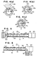
- Fig. 4 is a cross sectional view for explanation of the ion emission when ions are emitted and the suction of outside air when discharge needles are cleaned
- Fig. 4a is an enlarged cross sectional view taken along line 4(a)-4(a) of Fig. 1
- Fig. 4b is a an enlarged cross sectional view taken along line 4(b)-4(b) of Fig. 2
- Fig. 4c is a an enlarged cross sectional view taken along line 4(c)-4(c) of Fig. 3.
- a static eliminator 10 has a fixed hollow cylindrical housing such as a first cylinder 12 and an inside hollow cylinder or a second cylinder 14 which is rotatably positioned inside of the first cylinder 12 to clean discharge needles 16.
- Each of these cylinders 12 and 14 is closed by a cover 26 at its one end, and a driver 18 which is provided with a drive body 18a for rotationally driving the second cylinder 14, power supply 20 provided with a power supply body 20a and a fan with filter 24 are disposed at the other end.
- the discharge needles are provided with a dust sensor, not shown, to indicate the time of cleaning of discharge needles, if necessary.
- the first cylinder 12 is formed with openings 12a in a line along the first cylinder 12.
- the first cylinder 12 is provided with brushes 12b to remove the dust from the discharge needles 16 by wiping them, see Figs. 4b and 4c.
- the second cylinder 14 is formed with ion discharging openings 14c which are in alignment with the openings 12a of the first cylinder 12 at the rotational position of the second cylinder 14 in which ions are generated. Consequently ions 28 which are generated by discharge needles 16 provided inside of the second cylinder 14 are emitted or discharged through the openings 14c and the openings 12a.
- the second cylinder 14 is provided with a portion 14b which closes the other openings 12a except one opening 12a of the first cylinder 12 at the rotational position in which the discharge needles are cleaned. Furthermore, as shown in Fig.
- the second cylinder 14 is formed with one outside air sucking opening 14a which is in alignment with one of the openings such as the opening of the first cylinder adjacent the cover 26 in the first embodiment. Consequently the outside air is sucked in the second cylinder 14 though the openings.
- the outside air is sucked in the second cylinder 14 only through the opening 12a of the first cylinder 12 and the outside air sucking opening 14a of the second cylinder 14 and then inside the second cylinder 14 the floating dust is carried toward the filter 24 together with the outside air thus sucked.
- the filter 24 gathers the dust and only clean air is discharged outside.
- Fig. 5 is a cross sectional view for explanation of a static eliminator according to the second embodiment of the present invention when discharge needles are cleaned.
- the fan 22 with filter is provided on the first cylinder 12 and the second cylinder 14 at the opposite side of the driver 18 and the power supply 20.
- the discharging operation and the cleaning operation are similar to those of the first embodiment.
- Fig. 6 is a cross sectional view for explanation of a static eliminator according to the third embodiment of the present invention when discharge needles are cleaned.
- the fan 22 with filter is provided adjacent the driver 18.
- the discharging operation and the cleaning operation are similar to those of the first embodiment.
- the housing of the static eliminator is of a bar type
- the housing of the static eliminator is of a box type.
- the box type of static eliminator includes a type of calm static eliminator in which emission or discharge of ions is made by coulombic repulsion not using air blow by the fan and the other type of static eliminator with fan in which emission or discharge of ions is made using air blow by the fan, and therefore these types of static eliminator will be explained individually.
- Fig. 9 is a view for explanation of a box type of calm static eliminator according to the 4th embodiment of the present invention
- Fig. 9a is a front view of the static eliminator
- Fig. 9b is a cross sectional view of the static eliminator.
- the static eliminator 50 has a box type of housing 52.
- the housing 52 is formed with circular openings 52a at its front portion to emit outwardly ions which are generated from the discharge needles 54 disposed inside the housing 52.
- a plurality of discharge needles, 6 discharge needles in this embodiment, are disposed circumferentially.
- the discharge needles are provided with dust sensor, not shown, to sense dirtiness of the discharge needle and indicate the time when the discharge needles should be cleaned in response of extent of dirtiness.
- a brush 56 is disposed to wipe each of discharged needles 54.
- the brushes 56 are provided on arms 58 at their ends, and each arm 58 is attached to an arm swing mechanism or brush driver 60 which is attached to the front portion 52b of the housing at the center position of discharge needles.
- the brush driver 60 swings the arms 58 within a predetermined region as indicated by arrows to wipe away the dust attached to the discharge needles 54 therefrom.
- a suction fan 64 with suction filter 62 is attached to the rear portion 52c of the housing 52.
- the arm 58 is brought to the position as in shown in Fig. 9a and ions are generated by power supplied from the power supply, not shown, to the discharge needles to carry out static elimination.
- the brush driver 60 is actuated to wipe away the dust attached to the discharge needles therefrom and to float the dust.
- the fan 64 with suction filter 64 is actuated to suck the floating dust in by outside air as indicated by the dotted arrows and to transfer the dust toward the suction fan 64. Finally the clean air in which the dust is removed is discharged outside of the housing 52.
- Fig. 10 is a cross sectional view for explanation of a box type of static eliminator with a fan according to the 5th embodiment of the present invention.
- the brush, the arm, and the brush driver as shown in Fig. 9 are omitted.
- an air blow fan 68 with filter 66 is attached to the rear portion 52c of the housing 52.
- the air blow fan 68 with filter 66 is actuated to suck the clean air in from the outside as shown in arrows, to send the clean air toward the discharge needles and to fly away the ions thus emitted.
- the air blow fan 68 is turned down and a shutter 69 is closed to shut off the air blow.
- only the suction fan 64 is actuated to remove the dust from the discharge needles.
- Fig. 11 is a cross sectional view for explanation of a box type of static eliminator with a fan according to the 6th embodiment of the present invention
- Fig. 11a shows the state inside the static eliminator at the time of cleaning
- Fig. 11b shows the state inside the static eliminator at the time of discharging.
- the brush, the arm, and the brush driver as shown in Fig. 9 are omitted.
- the suction fan and the air blow fan instead of the suction fan and the air blow fan as provided in the 5th embodiment one fan 72 with filter 70 is provided inside of rear portion 52 of the housing 52. The fan is used as a suction and air blow one.
- valves 74 and 76 are respectively brought to the upper positions and therefore the fan works as a suction one.
- outside air is sucked in through the openings 52a of the housing 52, and is passed through the filter 70 and the fan 72, and discharged through the opening 52e.
- the valves 72 and 74 are respectively brought to the lower positions.
- the fan 72 works as an air blow one.
- the outside air is sucked in through the opening 52d of the housing 52, passed through the filter 70 and the fan 72, sent toward the discharge needles 54, and finally discharged through the openings 52a.
- Fig. 12 is a cross sectional view for explanation of a box type of static eliminator with a fan according to the 7th embodiment of the present invention
- Fig. 12a shows the state inside the static eliminator at the time of cleaning
- Fig. 12b shows the state inside the static eliminator at the time of discharging.
- the brush, the arm, and the brush driver as shown in Fig. 9 are omitted.
- a suction and air blow fan is used as is the case with the 6th embodiment.
- the fan is mounted on the housing 52 between the rear portion 52c and the partition wall 52f so that the fan is rotatable around an axis of rotation 72a.
- the fan 72 is caused to rotate about the axis 72a in order to change over the directions of air blow from the fan 72. That is, at the time of cleaning as shown in Fig. 12a the filter 70 is positioned above the fan 72 and sends the air downwardly.
- the fan 72 works as a suction one. As shown in dotted arrows, outside air is sucked in through the openings 52a of the housing 52, and is passed through the filter 70 and the fan 72, and discharged through the opening 52e. Meanwhile at the time of static elimination as shown in Fig. 12b, the fan 72 is positioned above the filter 70.
- the fan 72 works as an air blow one. As shown in solid arrows, the outside air is sucked in through the opening 52e of the housing 52, passed through the filter 70 and the fan 72, sent toward the discharge needles 54, and finally discharged through the openings 52a.
- the static eliminator described in 1 to 7 embodiments is provided with a controller, not shown, which actuates the above-mentioned discharge needles rotating mechanism or the arm swing mechanism and the fan with filter, that is, an air blow fan or a suction and air blow fan to carry out the cleaning operation.
- the cleaning operation may be made by the external order signal or the signal from the outside or from the dust sensors of the discharge needles.
- Fig. 7 is a view for explanation of the timing of control of elimination operation and cleaning operation.
- the static eliminator usually eliminates static charge.
- a first cleaning is made to clean the discharge needles on the basis of control by the controller.
- cycle data and time data are input and compared with actual date and time.
- the cleaning is restarted, and after that time the cleaning will be carried out periodically.
- Fig. 8 is a flow chart for explanation of cleaning operation in accordance with the present invention.
- a first cleaning is carried out (step S10).
- Cycle data is input and the date for cleaning is calculated (step S12).
- the date for cleaning and date input from the calendar are compared to judge as whether today is the cleaning date or not, and the cleaning date is waited for (step S14).
- the input time indicating data and the time input from the clock are compared and the time coincidence is waited for (step S16).
- step S18 cleaning is carried out (step S18). Thereafter the step returns to S12 and the cleaning will be repeatedly carried out periodically.
- the cleaning is also carried out by the external order signal or the signal from the dust sensor.
- the cleaning operation is carried out periodically in accordance with the program, in case that the controller receives the external order signal, the program is interrupted in.
- the dust sensor senses the dust or contamination at the time of static elimination between the periodic cleanings and judges that the cleaning time comes, the program is also interrupted in. Then the cleaning operation is carried out.
Landscapes
- Physics & Mathematics (AREA)
- Engineering & Computer Science (AREA)
- Plasma & Fusion (AREA)
- Elimination Of Static Electricity (AREA)
- Electrostatic Separation (AREA)
Applications Claiming Priority (1)
| Application Number | Priority Date | Filing Date | Title |
|---|---|---|---|
| JP2006103793A JP2007280701A (ja) | 2006-04-05 | 2006-04-05 | 除電装置 |
Publications (3)
| Publication Number | Publication Date |
|---|---|
| EP1843438A2 true EP1843438A2 (fr) | 2007-10-10 |
| EP1843438A3 EP1843438A3 (fr) | 2012-06-20 |
| EP1843438B1 EP1843438B1 (fr) | 2014-03-12 |
Family
ID=38171320
Family Applications (1)
| Application Number | Title | Priority Date | Filing Date |
|---|---|---|---|
| EP07005515.7A Not-in-force EP1843438B1 (fr) | 2006-04-05 | 2007-03-16 | Éliminateur statique à entretien nul |
Country Status (4)
| Country | Link |
|---|---|
| US (2) | US7492568B2 (fr) |
| EP (1) | EP1843438B1 (fr) |
| JP (1) | JP2007280701A (fr) |
| CN (1) | CN101052263B (fr) |
Cited By (1)
| Publication number | Priority date | Publication date | Assignee | Title |
|---|---|---|---|---|
| EP2192662A3 (fr) * | 2008-11-27 | 2012-08-22 | Trinc.Org | Éliminateur statique sans ozone |
Families Citing this family (15)
| Publication number | Priority date | Publication date | Assignee | Title |
|---|---|---|---|---|
| KR100512137B1 (ko) * | 2004-08-13 | 2005-09-02 | (주)선재하이테크 | 공기통을 갖춘 펄스 교류고전압 코로나방전식 막대형정전기 제거장치 |
| KR101325843B1 (ko) * | 2009-06-05 | 2013-11-05 | 샤프 가부시키가이샤 | 이온 발생 장치 및 전기 기기 |
| CN101835332B (zh) * | 2010-05-14 | 2014-10-29 | 无锡市中联电子设备有限公司 | 一体式静电消除器 |
| JP2012128990A (ja) * | 2010-12-14 | 2012-07-05 | Sharp Corp | イオン発生機 |
| CN102711352A (zh) * | 2012-01-06 | 2012-10-03 | 无锡市中联电子设备有限公司 | 放电针 |
| US10980911B2 (en) | 2016-01-21 | 2021-04-20 | Global Plasma Solutions, Inc. | Flexible ion generator device |
| US11695259B2 (en) | 2016-08-08 | 2023-07-04 | Global Plasma Solutions, Inc. | Modular ion generator device |
| US11283245B2 (en) | 2016-08-08 | 2022-03-22 | Global Plasma Solutions, Inc. | Modular ion generator device |
| JP7169371B2 (ja) | 2018-02-12 | 2022-11-10 | グローバル プラズマ ソリューションズ,インコーポレイテッド | 自己洗浄イオン生成装置 |
| US11581709B2 (en) | 2019-06-07 | 2023-02-14 | Global Plasma Solutions, Inc. | Self-cleaning ion generator device |
| CN112956943A (zh) * | 2021-01-26 | 2021-06-15 | 上海稳巢信息科技有限公司 | 一种手持式防静电吸尘器 |
| CN112934767A (zh) * | 2021-01-26 | 2021-06-11 | 上海稳巢信息科技有限公司 | 一种排列式放电针清洁控制系统 |
| CN118284471A (zh) | 2021-08-30 | 2024-07-02 | 环球等离子解决方案公司 | 用于产生离子的自清洁装置 |
| CN114992763B (zh) | 2022-04-25 | 2024-06-25 | 北京小米移动软件有限公司 | 负离子发生装置及空气净化器 |
| JP2024037627A (ja) * | 2022-09-07 | 2024-03-19 | 株式会社キーエンス | 除電装置およびイオンバランス制御方法 |
Family Cites Families (17)
| Publication number | Priority date | Publication date | Assignee | Title |
|---|---|---|---|---|
| JPS6292971A (ja) * | 1985-10-19 | 1987-04-28 | Ricoh Co Ltd | コロナ放電による帯電ムラ防止方法とその装置 |
| US4734580A (en) * | 1986-06-16 | 1988-03-29 | The Simco Company, Inc. | Built-in ionizing electrode cleaning apparatus |
| JPH0386599A (ja) * | 1989-08-31 | 1991-04-11 | Koufu Nippon Denki Kk | 通帳のページめくり機構 |
| JPH08171254A (ja) * | 1994-12-15 | 1996-07-02 | Konica Corp | 帯電装置 |
| US5768087A (en) * | 1996-11-05 | 1998-06-16 | Ion Systems, Inc. | Method and apparatus for automatically cleaning ionizing electrodes |
| US7658891B1 (en) * | 1997-11-21 | 2010-02-09 | Barnes Ronald L | Air purification and decontamination for hazmat suits |
| US6419171B1 (en) * | 1999-02-24 | 2002-07-16 | Takayanagi Research Inc. | Static eliminator |
| US6464754B1 (en) * | 1999-10-07 | 2002-10-15 | Kairos, L.L.C. | Self-cleaning air purification system and process |
| AUPR160500A0 (en) * | 2000-11-21 | 2000-12-14 | Indigo Technologies Group Pty Ltd | Electrostatic filter |
| JP4614569B2 (ja) * | 2001-04-06 | 2011-01-19 | 一雄 岡野 | 吸引型イオナイザ |
| JP4738674B2 (ja) * | 2001-09-12 | 2011-08-03 | 株式会社Trinc | 防爆型バータイプ除電器 |
| JP2003296044A (ja) * | 2002-03-29 | 2003-10-17 | Fujitsu Ltd | 記憶装置および状態監視プログラム |
| JP4262488B2 (ja) * | 2003-01-29 | 2009-05-13 | シシド静電気株式会社 | 送風式イオン生成装置 |
| KR101111468B1 (ko) * | 2003-06-05 | 2012-02-21 | 시시도 세이덴기 가부시키가이샤 | 이온 생성 장치 |
| JP4358008B2 (ja) * | 2004-03-24 | 2009-11-04 | トヨタ自動車株式会社 | バータイプ除電器 |
| US7006923B1 (en) * | 2004-05-19 | 2006-02-28 | The United States Of America As Represented By The Secretary Of The Navy | Distributed biohazard surveillance system and apparatus for adaptive collection and particulate sampling |
| US20060045559A1 (en) * | 2004-08-31 | 2006-03-02 | Xerox Corporation | Method of actuating a cleaning system and a printing machine including the same |
-
2006
- 2006-04-05 JP JP2006103793A patent/JP2007280701A/ja active Pending
-
2007
- 2007-03-16 EP EP07005515.7A patent/EP1843438B1/fr not_active Not-in-force
- 2007-03-20 US US11/688,784 patent/US7492568B2/en active Active
- 2007-04-05 CN CN2007100898217A patent/CN101052263B/zh not_active Expired - Fee Related
-
2009
- 2009-01-15 US US12/354,658 patent/US20090128984A1/en not_active Abandoned
Cited By (1)
| Publication number | Priority date | Publication date | Assignee | Title |
|---|---|---|---|---|
| EP2192662A3 (fr) * | 2008-11-27 | 2012-08-22 | Trinc.Org | Éliminateur statique sans ozone |
Also Published As
| Publication number | Publication date |
|---|---|
| EP1843438A3 (fr) | 2012-06-20 |
| CN101052263A (zh) | 2007-10-10 |
| US7492568B2 (en) | 2009-02-17 |
| EP1843438B1 (fr) | 2014-03-12 |
| JP2007280701A (ja) | 2007-10-25 |
| CN101052263B (zh) | 2010-12-08 |
| US20070258183A1 (en) | 2007-11-08 |
| US20090128984A1 (en) | 2009-05-21 |
Similar Documents
| Publication | Publication Date | Title |
|---|---|---|
| EP1843438A2 (fr) | Éliminateur statique à entretien nul | |
| EP2417894B1 (fr) | Robot de nettoyage | |
| KR20090060601A (ko) | 공기조화기와 그 필터 청소방법 및 필터 청소 장치 | |
| KR20100132893A (ko) | 청소장치 및 이를 이용한 먼지 포집 방법 | |
| JP7289039B2 (ja) | フィルタ清掃装置を備える空気調和機及び空気調和機のエアフィルタ清掃方法 | |
| EP4400021A1 (fr) | Système de nettoyage et station de base | |
| KR20140136814A (ko) | 먼지털이장치가 장착된 산업진공청소기 | |
| CN219021002U (zh) | 自动清洁设备 | |
| JP2008057923A (ja) | 空気調和機用清掃装置と空気調和機 | |
| KR102022290B1 (ko) | 로봇 청소기 | |
| JP2007125294A (ja) | 集塵器およびそれを備えた電気掃除機 | |
| JP2008051430A (ja) | 空気調和機の室内機 | |
| JPWO2008062876A1 (ja) | 空気調和機の室内機 | |
| JP2015112204A (ja) | 電気掃除機 | |
| CN219888081U (zh) | 一种矿用通风设备 | |
| KR100750724B1 (ko) | 진공청소기의 흡입 브러시 | |
| KR102482042B1 (ko) | 물걸레 로봇청소기 | |
| JPH1133327A (ja) | フィルター清掃装置 | |
| CN100480594C (zh) | 空调机 | |
| JP2001327938A (ja) | 車両用シート清掃装置 | |
| CN215687472U (zh) | 一种扫地机器人的清扫装置 | |
| CN115752615B (zh) | 一种水表检测装置 | |
| CN113454396B (zh) | 空气调节机 | |
| KR20070016420A (ko) | 청소기의 흡입 유닛 | |
| CN113413093B (zh) | 移动机器人的清洁方法和装置、存储介质、电子装置 |
Legal Events
| Date | Code | Title | Description |
|---|---|---|---|
| PUAI | Public reference made under article 153(3) epc to a published international application that has entered the european phase |
Free format text: ORIGINAL CODE: 0009012 |
|
| 17P | Request for examination filed |
Effective date: 20070316 |
|
| AK | Designated contracting states |
Kind code of ref document: A2 Designated state(s): AT BE BG CH CY CZ DE DK EE ES FI FR GB GR HU IE IS IT LI LT LU LV MC MT NL PL PT RO SE SI SK TR |
|
| AX | Request for extension of the european patent |
Extension state: AL BA HR MK YU |
|
| PUAL | Search report despatched |
Free format text: ORIGINAL CODE: 0009013 |
|
| AK | Designated contracting states |
Kind code of ref document: A3 Designated state(s): AT BE BG CH CY CZ DE DK EE ES FI FR GB GR HU IE IS IT LI LT LU LV MC MT NL PL PT RO SE SI SK TR |
|
| AX | Request for extension of the european patent |
Extension state: AL BA HR MK RS |
|
| RIC1 | Information provided on ipc code assigned before grant |
Ipc: H01T 19/04 20060101AFI20120516BHEP Ipc: H01T 23/00 20060101ALI20120516BHEP Ipc: H01T 19/00 20060101ALI20120516BHEP |
|
| AKX | Designation fees paid |
Designated state(s): AT BE BG CH CY CZ DE DK EE ES FI FR GB GR HU IE IS IT LI LT LU LV MC MT NL PL PT RO SE SI SK TR |
|
| GRAP | Despatch of communication of intention to grant a patent |
Free format text: ORIGINAL CODE: EPIDOSNIGR1 |
|
| INTG | Intention to grant announced |
Effective date: 20130510 |
|
| GRAP | Despatch of communication of intention to grant a patent |
Free format text: ORIGINAL CODE: EPIDOSNIGR1 |
|
| INTG | Intention to grant announced |
Effective date: 20130925 |
|
| GRAS | Grant fee paid |
Free format text: ORIGINAL CODE: EPIDOSNIGR3 |
|
| GRAA | (expected) grant |
Free format text: ORIGINAL CODE: 0009210 |
|
| AK | Designated contracting states |
Kind code of ref document: B1 Designated state(s): AT BE BG CH CY CZ DE DK EE ES FI FR GB GR HU IE IS IT LI LT LU LV MC MT NL PL PT RO SE SI SK TR |
|
| REG | Reference to a national code |
Ref country code: GB Ref legal event code: FG4D |
|
| REG | Reference to a national code |
Ref country code: CH Ref legal event code: EP |
|
| REG | Reference to a national code |
Ref country code: AT Ref legal event code: REF Ref document number: 656842 Country of ref document: AT Kind code of ref document: T Effective date: 20140315 |
|
| REG | Reference to a national code |
Ref country code: IE Ref legal event code: FG4D |
|
| REG | Reference to a national code |
Ref country code: DE Ref legal event code: R096 Ref document number: 602007035469 Country of ref document: DE Effective date: 20140424 |
|
| REG | Reference to a national code |
Ref country code: NL Ref legal event code: VDEP Effective date: 20140312 |
|
| PG25 | Lapsed in a contracting state [announced via postgrant information from national office to epo] |
Ref country code: LT Free format text: LAPSE BECAUSE OF FAILURE TO SUBMIT A TRANSLATION OF THE DESCRIPTION OR TO PAY THE FEE WITHIN THE PRESCRIBED TIME-LIMIT Effective date: 20140312 |
|
| REG | Reference to a national code |
Ref country code: AT Ref legal event code: MK05 Ref document number: 656842 Country of ref document: AT Kind code of ref document: T Effective date: 20140312 |
|
| REG | Reference to a national code |
Ref country code: LT Ref legal event code: MG4D |
|
| PG25 | Lapsed in a contracting state [announced via postgrant information from national office to epo] |
Ref country code: SE Free format text: LAPSE BECAUSE OF FAILURE TO SUBMIT A TRANSLATION OF THE DESCRIPTION OR TO PAY THE FEE WITHIN THE PRESCRIBED TIME-LIMIT Effective date: 20140312 Ref country code: FI Free format text: LAPSE BECAUSE OF FAILURE TO SUBMIT A TRANSLATION OF THE DESCRIPTION OR TO PAY THE FEE WITHIN THE PRESCRIBED TIME-LIMIT Effective date: 20140312 Ref country code: CY Free format text: LAPSE BECAUSE OF FAILURE TO SUBMIT A TRANSLATION OF THE DESCRIPTION OR TO PAY THE FEE WITHIN THE PRESCRIBED TIME-LIMIT Effective date: 20140312 |
|
| PG25 | Lapsed in a contracting state [announced via postgrant information from national office to epo] |
Ref country code: LV Free format text: LAPSE BECAUSE OF FAILURE TO SUBMIT A TRANSLATION OF THE DESCRIPTION OR TO PAY THE FEE WITHIN THE PRESCRIBED TIME-LIMIT Effective date: 20140312 |
|
| PG25 | Lapsed in a contracting state [announced via postgrant information from national office to epo] |
Ref country code: CZ Free format text: LAPSE BECAUSE OF FAILURE TO SUBMIT A TRANSLATION OF THE DESCRIPTION OR TO PAY THE FEE WITHIN THE PRESCRIBED TIME-LIMIT Effective date: 20140312 Ref country code: IS Free format text: LAPSE BECAUSE OF FAILURE TO SUBMIT A TRANSLATION OF THE DESCRIPTION OR TO PAY THE FEE WITHIN THE PRESCRIBED TIME-LIMIT Effective date: 20140712 Ref country code: BE Free format text: LAPSE BECAUSE OF FAILURE TO SUBMIT A TRANSLATION OF THE DESCRIPTION OR TO PAY THE FEE WITHIN THE PRESCRIBED TIME-LIMIT Effective date: 20140312 Ref country code: RO Free format text: LAPSE BECAUSE OF FAILURE TO SUBMIT A TRANSLATION OF THE DESCRIPTION OR TO PAY THE FEE WITHIN THE PRESCRIBED TIME-LIMIT Effective date: 20140312 Ref country code: BG Free format text: LAPSE BECAUSE OF FAILURE TO SUBMIT A TRANSLATION OF THE DESCRIPTION OR TO PAY THE FEE WITHIN THE PRESCRIBED TIME-LIMIT Effective date: 20140612 Ref country code: EE Free format text: LAPSE BECAUSE OF FAILURE TO SUBMIT A TRANSLATION OF THE DESCRIPTION OR TO PAY THE FEE WITHIN THE PRESCRIBED TIME-LIMIT Effective date: 20140312 Ref country code: NL Free format text: LAPSE BECAUSE OF FAILURE TO SUBMIT A TRANSLATION OF THE DESCRIPTION OR TO PAY THE FEE WITHIN THE PRESCRIBED TIME-LIMIT Effective date: 20140312 |
|
| REG | Reference to a national code |
Ref country code: CH Ref legal event code: PL |
|
| PG25 | Lapsed in a contracting state [announced via postgrant information from national office to epo] |
Ref country code: PL Free format text: LAPSE BECAUSE OF FAILURE TO SUBMIT A TRANSLATION OF THE DESCRIPTION OR TO PAY THE FEE WITHIN THE PRESCRIBED TIME-LIMIT Effective date: 20140312 Ref country code: AT Free format text: LAPSE BECAUSE OF FAILURE TO SUBMIT A TRANSLATION OF THE DESCRIPTION OR TO PAY THE FEE WITHIN THE PRESCRIBED TIME-LIMIT Effective date: 20140312 Ref country code: ES Free format text: LAPSE BECAUSE OF FAILURE TO SUBMIT A TRANSLATION OF THE DESCRIPTION OR TO PAY THE FEE WITHIN THE PRESCRIBED TIME-LIMIT Effective date: 20140312 Ref country code: SK Free format text: LAPSE BECAUSE OF FAILURE TO SUBMIT A TRANSLATION OF THE DESCRIPTION OR TO PAY THE FEE WITHIN THE PRESCRIBED TIME-LIMIT Effective date: 20140312 |
|
| REG | Reference to a national code |
Ref country code: DE Ref legal event code: R097 Ref document number: 602007035469 Country of ref document: DE |
|
| PG25 | Lapsed in a contracting state [announced via postgrant information from national office to epo] |
Ref country code: PT Free format text: LAPSE BECAUSE OF FAILURE TO SUBMIT A TRANSLATION OF THE DESCRIPTION OR TO PAY THE FEE WITHIN THE PRESCRIBED TIME-LIMIT Effective date: 20140714 |
|
| REG | Reference to a national code |
Ref country code: IE Ref legal event code: MM4A |
|
| PLBE | No opposition filed within time limit |
Free format text: ORIGINAL CODE: 0009261 |
|
| STAA | Information on the status of an ep patent application or granted ep patent |
Free format text: STATUS: NO OPPOSITION FILED WITHIN TIME LIMIT |
|
| PG25 | Lapsed in a contracting state [announced via postgrant information from national office to epo] |
Ref country code: LI Free format text: LAPSE BECAUSE OF NON-PAYMENT OF DUE FEES Effective date: 20140331 Ref country code: CH Free format text: LAPSE BECAUSE OF NON-PAYMENT OF DUE FEES Effective date: 20140331 Ref country code: IE Free format text: LAPSE BECAUSE OF NON-PAYMENT OF DUE FEES Effective date: 20140316 Ref country code: DK Free format text: LAPSE BECAUSE OF FAILURE TO SUBMIT A TRANSLATION OF THE DESCRIPTION OR TO PAY THE FEE WITHIN THE PRESCRIBED TIME-LIMIT Effective date: 20140312 Ref country code: MC Free format text: LAPSE BECAUSE OF FAILURE TO SUBMIT A TRANSLATION OF THE DESCRIPTION OR TO PAY THE FEE WITHIN THE PRESCRIBED TIME-LIMIT Effective date: 20140312 |
|
| 26N | No opposition filed |
Effective date: 20141215 |
|
| REG | Reference to a national code |
Ref country code: DE Ref legal event code: R097 Ref document number: 602007035469 Country of ref document: DE Effective date: 20141215 |
|
| PG25 | Lapsed in a contracting state [announced via postgrant information from national office to epo] |
Ref country code: IT Free format text: LAPSE BECAUSE OF FAILURE TO SUBMIT A TRANSLATION OF THE DESCRIPTION OR TO PAY THE FEE WITHIN THE PRESCRIBED TIME-LIMIT Effective date: 20140312 |
|
| PG25 | Lapsed in a contracting state [announced via postgrant information from national office to epo] |
Ref country code: SI Free format text: LAPSE BECAUSE OF FAILURE TO SUBMIT A TRANSLATION OF THE DESCRIPTION OR TO PAY THE FEE WITHIN THE PRESCRIBED TIME-LIMIT Effective date: 20140312 |
|
| PG25 | Lapsed in a contracting state [announced via postgrant information from national office to epo] |
Ref country code: MT Free format text: LAPSE BECAUSE OF FAILURE TO SUBMIT A TRANSLATION OF THE DESCRIPTION OR TO PAY THE FEE WITHIN THE PRESCRIBED TIME-LIMIT Effective date: 20140312 |
|
| REG | Reference to a national code |
Ref country code: FR Ref legal event code: PLFP Year of fee payment: 10 |
|
| PG25 | Lapsed in a contracting state [announced via postgrant information from national office to epo] |
Ref country code: GR Free format text: LAPSE BECAUSE OF FAILURE TO SUBMIT A TRANSLATION OF THE DESCRIPTION OR TO PAY THE FEE WITHIN THE PRESCRIBED TIME-LIMIT Effective date: 20140613 |
|
| PG25 | Lapsed in a contracting state [announced via postgrant information from national office to epo] |
Ref country code: LU Free format text: LAPSE BECAUSE OF NON-PAYMENT OF DUE FEES Effective date: 20140316 Ref country code: HU Free format text: LAPSE BECAUSE OF FAILURE TO SUBMIT A TRANSLATION OF THE DESCRIPTION OR TO PAY THE FEE WITHIN THE PRESCRIBED TIME-LIMIT; INVALID AB INITIO Effective date: 20070316 Ref country code: TR Free format text: LAPSE BECAUSE OF FAILURE TO SUBMIT A TRANSLATION OF THE DESCRIPTION OR TO PAY THE FEE WITHIN THE PRESCRIBED TIME-LIMIT Effective date: 20140312 |
|
| REG | Reference to a national code |
Ref country code: FR Ref legal event code: PLFP Year of fee payment: 11 |
|
| REG | Reference to a national code |
Ref country code: FR Ref legal event code: PLFP Year of fee payment: 12 |
|
| PGFP | Annual fee paid to national office [announced via postgrant information from national office to epo] |
Ref country code: FR Payment date: 20230208 Year of fee payment: 17 |
|
| PGFP | Annual fee paid to national office [announced via postgrant information from national office to epo] |
Ref country code: DE Payment date: 20240130 Year of fee payment: 18 Ref country code: GB Payment date: 20240201 Year of fee payment: 18 |
|
| PG25 | Lapsed in a contracting state [announced via postgrant information from national office to epo] |
Ref country code: FR Free format text: LAPSE BECAUSE OF NON-PAYMENT OF DUE FEES Effective date: 20240331 |
|
| PG25 | Lapsed in a contracting state [announced via postgrant information from national office to epo] |
Ref country code: FR Free format text: LAPSE BECAUSE OF NON-PAYMENT OF DUE FEES Effective date: 20240331 |
|
| REG | Reference to a national code |
Ref country code: DE Ref legal event code: R119 Ref document number: 602007035469 Country of ref document: DE |
|
| GBPC | Gb: european patent ceased through non-payment of renewal fee |
Effective date: 20250316 |
|
| PG25 | Lapsed in a contracting state [announced via postgrant information from national office to epo] |
Ref country code: DE Free format text: LAPSE BECAUSE OF NON-PAYMENT OF DUE FEES Effective date: 20251001 |
|
| PG25 | Lapsed in a contracting state [announced via postgrant information from national office to epo] |
Ref country code: GB Free format text: LAPSE BECAUSE OF NON-PAYMENT OF DUE FEES Effective date: 20250316 |