EP1843579A2 - Dünne Bildanzeigevorrichtung - Google Patents
Dünne Bildanzeigevorrichtung Download PDFInfo
- Publication number
- EP1843579A2 EP1843579A2 EP07251380A EP07251380A EP1843579A2 EP 1843579 A2 EP1843579 A2 EP 1843579A2 EP 07251380 A EP07251380 A EP 07251380A EP 07251380 A EP07251380 A EP 07251380A EP 1843579 A2 EP1843579 A2 EP 1843579A2
- Authority
- EP
- European Patent Office
- Prior art keywords
- image display
- display apparatus
- thin image
- thin
- apparatus body
- Prior art date
- Legal status (The legal status is an assumption and is not a legal conclusion. Google has not performed a legal analysis and makes no representation as to the accuracy of the status listed.)
- Withdrawn
Links
Images




Classifications
-
- H—ELECTRICITY
- H04—ELECTRIC COMMUNICATION TECHNIQUE
- H04N—PICTORIAL COMMUNICATION, e.g. TELEVISION
- H04N5/00—Details of television systems
- H04N5/64—Constructional details of receivers, e.g. cabinets or dust covers
-
- H—ELECTRICITY
- H04—ELECTRIC COMMUNICATION TECHNIQUE
- H04N—PICTORIAL COMMUNICATION, e.g. TELEVISION
- H04N5/00—Details of television systems
- H04N5/64—Constructional details of receivers, e.g. cabinets or dust covers
- H04N5/65—Holding-devices for protective discs or for picture masks
-
- F—MECHANICAL ENGINEERING; LIGHTING; HEATING; WEAPONS; BLASTING
- F16—ENGINEERING ELEMENTS AND UNITS; GENERAL MEASURES FOR PRODUCING AND MAINTAINING EFFECTIVE FUNCTIONING OF MACHINES OR INSTALLATIONS; THERMAL INSULATION IN GENERAL
- F16M—FRAMES, CASINGS OR BEDS OF ENGINES, MACHINES OR APPARATUS, NOT SPECIFIC TO ENGINES, MACHINES OR APPARATUS PROVIDED FOR ELSEWHERE; STANDS; SUPPORTS
- F16M11/00—Stands or trestles as supports for apparatus or articles placed thereon ; Stands for scientific apparatus such as gravitational force meters
- F16M11/02—Heads
- F16M11/04—Means for attachment of apparatus; Means allowing adjustment of the apparatus relatively to the stand
- F16M11/06—Means for attachment of apparatus; Means allowing adjustment of the apparatus relatively to the stand allowing pivoting
- F16M11/10—Means for attachment of apparatus; Means allowing adjustment of the apparatus relatively to the stand allowing pivoting around a horizontal axis
-
- F—MECHANICAL ENGINEERING; LIGHTING; HEATING; WEAPONS; BLASTING
- F16—ENGINEERING ELEMENTS AND UNITS; GENERAL MEASURES FOR PRODUCING AND MAINTAINING EFFECTIVE FUNCTIONING OF MACHINES OR INSTALLATIONS; THERMAL INSULATION IN GENERAL
- F16M—FRAMES, CASINGS OR BEDS OF ENGINES, MACHINES OR APPARATUS, NOT SPECIFIC TO ENGINES, MACHINES OR APPARATUS PROVIDED FOR ELSEWHERE; STANDS; SUPPORTS
- F16M11/00—Stands or trestles as supports for apparatus or articles placed thereon ; Stands for scientific apparatus such as gravitational force meters
- F16M11/20—Undercarriages with or without wheels
- F16M11/2007—Undercarriages with or without wheels comprising means allowing pivoting adjustment
- F16M11/2014—Undercarriages with or without wheels comprising means allowing pivoting adjustment around a vertical axis
-
- F—MECHANICAL ENGINEERING; LIGHTING; HEATING; WEAPONS; BLASTING
- F16—ENGINEERING ELEMENTS AND UNITS; GENERAL MEASURES FOR PRODUCING AND MAINTAINING EFFECTIVE FUNCTIONING OF MACHINES OR INSTALLATIONS; THERMAL INSULATION IN GENERAL
- F16M—FRAMES, CASINGS OR BEDS OF ENGINES, MACHINES OR APPARATUS, NOT SPECIFIC TO ENGINES, MACHINES OR APPARATUS PROVIDED FOR ELSEWHERE; STANDS; SUPPORTS
- F16M13/00—Other supports for positioning apparatus or articles; Means for steadying hand-held apparatus or articles
- F16M13/02—Other supports for positioning apparatus or articles; Means for steadying hand-held apparatus or articles for supporting on, or attaching to, an object, e.g. tree, gate, window-frame, cycle
- F16M13/027—Ceiling supports
-
- H—ELECTRICITY
- H04—ELECTRIC COMMUNICATION TECHNIQUE
- H04B—TRANSMISSION
- H04B3/00—Line transmission systems
- H04B3/54—Systems for transmission via power distribution lines
-
- H—ELECTRICITY
- H04—ELECTRIC COMMUNICATION TECHNIQUE
- H04N—PICTORIAL COMMUNICATION, e.g. TELEVISION
- H04N5/00—Details of television systems
- H04N5/64—Constructional details of receivers, e.g. cabinets or dust covers
- H04N5/655—Construction or mounting of chassis, e.g. for varying the elevation of the tube
-
- H—ELECTRICITY
- H04—ELECTRIC COMMUNICATION TECHNIQUE
- H04N—PICTORIAL COMMUNICATION, e.g. TELEVISION
- H04N9/00—Details of colour television systems
- H04N9/12—Picture reproducers
- H04N9/31—Projection devices for colour picture display, e.g. using electronic spatial light modulators [ESLM]
- H04N9/3141—Constructional details thereof
-
- H—ELECTRICITY
- H04—ELECTRIC COMMUNICATION TECHNIQUE
- H04B—TRANSMISSION
- H04B2203/00—Indexing scheme relating to line transmission systems
- H04B2203/54—Aspects of powerline communications not already covered by H04B3/54 and its subgroups
- H04B2203/5429—Applications for powerline communications
- H04B2203/5441—Wireless systems or telephone
-
- H—ELECTRICITY
- H04—ELECTRIC COMMUNICATION TECHNIQUE
- H04B—TRANSMISSION
- H04B2203/00—Indexing scheme relating to line transmission systems
- H04B2203/54—Aspects of powerline communications not already covered by H04B3/54 and its subgroups
- H04B2203/5429—Applications for powerline communications
- H04B2203/5454—Adapter and plugs
-
- H—ELECTRICITY
- H04—ELECTRIC COMMUNICATION TECHNIQUE
- H04N—PICTORIAL COMMUNICATION, e.g. TELEVISION
- H04N5/00—Details of television systems
- H04N5/63—Generation or supply of power specially adapted for television receivers
Definitions
- the present invention contains subject matter related to Japanese Patent Application JP 2006-105712 filed with the Japan Patent Office on April 6, 2006.
- This invention relates to a comparatively light-weighted thin image display apparatus which uses a thin display panel such as an organic electroluminescence display panel or a liquid crystal display panel.
- a planar type display apparatus which is suspended on the ceiling is in the past known and disclosed in Japanese Patent Laid-Open No. 2002-32033 .
- the suspended thin image display apparatus is disadvantageous in that the arrangement location thereof is restricted.
- a thin image display apparatus which may not require apparently miscellaneous wiring lines and can be installed while providing a fine sight. Also it is demanded to provide a thin image display apparatus which can receive an image signal even if the sensitivity varies depending upon the position of a receiver antenna and is free from restriction of the installation location.
- a thin image display apparatus including a thin image display apparatus body, a hollow support member having a first end at which the hollow support member supports the thin image display apparatus body through a rocking mechanism section and a second end at which a plug element configured to engage with an illumination apparatus wiring member attached to the ceiling or a wall is provided, and a power line extending through the hollow support member and configured to connect the plug element and the thin image display apparatus body to each other, the thin image display apparatus body receiving, when the plug element engages with the illumination apparatus wiring member, power supplied through the power line together with a modulated image signal supplied through the power line such that an image based on the modulated image signal is displayed on the thin image display apparatus body.
- a thin image display apparatus including a thin image display apparatus body configured to receive a modulated image signal transmitted by radio transmission from a receiver apparatus provided separately, a hollow support member having a first end at which the hollow support member supports the thin image display apparatus body through a rocking mechanism section and a second end at which a plug element configured to engage with an illumination apparatus wiring member attached to the ceiling or a wall is provided, and a power line extending through the hollow support member and configured to connect the plug element and the thin image display apparatus body to each other, the thin image display apparatus body receiving, when the plug section engages with the illumination apparatus wiring device, power supplied through the power line, receiving the modulated image signal transmitted by radio such that an image based on the modulated image signal is displayed on the thin image display apparatus body.
- the thin image display apparatus With the thin image display apparatus, power is supplied through the power line disposed in the inside of the support member and an image signal is supplied through the power line or by radio communication. Therefore, the thin image display apparatus do not become apparently miscellaneous and can be installed while keeping a fine appearance.
- an image signal is supplied from the reception apparatus, which is provided separately from the thin image display apparatus body, through the power line or by radio communication. Therefore, there is no restriction to wiring, and a receiver antenna can be placed at a position at which it exhibits a high sensitivity. Consequently, there is no disadvantage by failure of reception of an image signal, and there is no restriction to the arrangement location of the thin image display apparatus body.
- FIGS. 1A to 7 there is shown a thin image display apparatus to which the present invention is applied.
- the thin image display apparatus is generally configured such that a thin image display apparatus body is suspended on the ceiling using a support member and power is supplied to the thin image display apparatus body through a power line disposed in the inside of the support member and also an image signal is supplied through the power line.
- the thin image display apparatus shown includes a thin image display apparatus body 1 of a comparatively small thickness which uses a comparatively light-weighted thin display panel such as an organic electroluminescence display panel or a liquid crystal display panel.
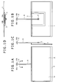
- the front face of the thin image display apparatus body 1 includes an image display section 1a and a framework 2 surrounding the image display section 1a as seen in FIG. 1A.
- FIG. 1B The rear face of the thin image display apparatus body 1 is shown in FIG. 1B.
- the rear face of the thin image display apparatus body 1 has a driving display circuit accommodation section 3 provided at an upper portion of a central portion of the rear face thereof and covering such a driving display circuit as shown in FIG. 7 hereinafter described for displaying an image on the image display section 1a.
- a heat radiating opening 4 in the form of a slit for radiating heat generated from the driving display circuit therethrough is provided at an upper portion of the driving display circuit accommodation section 3 as seen in FIG. 1D.
- a hollow support member 6 for suspending the thin image display apparatus body 1 on a ceiling 5 or a wall is attached at a lower or second end thereof to the driving display circuit accommodation section 3 of the rear face of the thin image display apparatus body 1 through a rocking mechanism 7.
- the hollow support member 6 is formed as a rigid member so that it receives tensile stress arising from the weight of the thin image display apparatus body 1 to hold the thin image display apparatus body 1 in a predetermined posture.
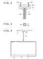
- a plug 9 for being mechanically secured to a ceiling rosette 8 to establish electric connection is provided at an upper or first end of the support member 6.
- the ceiling rosette 8 is a ceiling wiring device for an illumination apparatus which is secured to the ceiling 5 or the like of a house and suspends an illumination apparatus thereon for establishing electric connection.
- the plug 9 is formed by integral molding of a synthetic resin material at the first end of the support member 6 and including a pair of electrodes 10a and 10b each formed from an L-shaped metal member and disposed in a spaced relationship by a predetermined distance from each other.
- the electrodes 10a and 10b are connected to power lines 11a and 11b disposed in the inside of the hollow support member 6.
- the plug 9 includes a plug body 9a configured so as to hold the electrodes 10a and 10b and the support member 6 so that the total load of the thin image display apparatus body 1, support member 6 and power lines 11a and 11b can be supported by the electrodes 10a and 10b when the electrodes 10a and 10b are mechanically secured to the ceiling rosette 8.
- FIG. 3 which shows a sectional view of the support member 6 taken along line III-III of FIG. 1A
- the two power lines 11a and 11b are disposed in the hollow of the hollow support member 6.
- the power lines 11a and 11b are led to the driving display circuit accommodation section 3 of the thin image display apparatus body 1 and supply power to a driving display circuit and so forth hereinafter described therethrough.
- the plug 9 is mechanically secured to the ceiling rosette 8 by means of the electrodes 10a and 10b each in the form of an L-shaped metal member and is electrically connected to power supply terminals of the ceiling rosette 8.
- the rocking mechanism 7 includes a support shaft 6a provided at the second end of the support member 6 and extending leftwardly and rightwardly, and a bearing 7a provided integrally with the driving display circuit accommodation section 3 on the rear face of the thin image display apparatus body 1 so as to support the support shaft 6a.
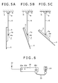
- the rocking mechanism 7 can fix the thin image display apparatus body 1 at an arbitrary angular position. Consequently, the thin image display apparatus body 1 can change its angle or posture within a range from a vertical angular position at which the thin image display apparatus body 1 lies in parallel to the support member 6 to a horizontal angular position at which the thin image display apparatus body 1 lies in a horizontal direction as seen in FIGS. 5A, 5B and 5C. In short, the thin image display apparatus body 1 can be held in a posture of a predetermined angle in accordance with a viewing condition.
- the length of the support member 6 is set greater than the length from the rocking mechanism 7 to the upper end of the thin image display apparatus body 1, then the degree of freedom in installation of the ceiling rosette 8 to which the plug 9 is to be attached can be increased.
- the rocking mechanism 7 is provided at a position between the vertical center and the upper end of the rear face of the driving display circuit accommodation section 3 of the thin image display apparatus body 1 and substantially at the center in the leftward and rightward direction, then the fulcrum is positioned closely to the center of gravity of the thin image display apparatus body 1. Therefore, even if the angle of the thin image display apparatus body 1 is set as seen in FIG. 5A, 5B or 5C, no bending stress is applied to the support member 6 but tensile stress is applied. Therefore, no deforming force is applied to any of the plug 9 and the ceiling rosette 8 to which the plug 9 is attached, and consequently, the strength of them can be maintained.
- an image signal is transmitted to the thin image display apparatus body 1 by power line communication (PLC) using a power line 29 as seen in FIGS. 6 and 7.
- PLC power line communication
- a receiver apparatus 20 is provided separately from the thin image display apparatus body 1. Further, a driving display circuit 21 is provided in the thin image display apparatus body 1 as seen in FIG. 7.
- the receiver apparatus 20 includes a reception signal input terminal 20a to which a reception signal is supplied from a receiver antenna 22, an external signal input terminal 20b to which an image signal is supplied from the outside, and a power supply input terminal 20c for being connected to a home plug socket 24 through a power supply cable 23.
- the receiver apparatus 20 includes a tuner 25 which demodulates a reception signal received by the receiver antenna 22 and supplies the demodulated image signal to a predetermined modulator 26. Meanwhile, the image signal from the external signal input terminal 20b is supplied to the modulator 26.
- the image signal modulated by the modulator 26 is supplied to a superimposing circuit 27.
- the superimposing circuit 27 superimposes the image signal on the power line 29 through the power supply input terminal 20c using a technique which utilizes a power line as a communication line, that is, the technique of power line communication.
- the image signal modulated by the modulator 26 successively passes the superimposing circuit 27, power supply input terminal 20c and power supply cable 23 and is superimposed on a power line 29 in a home from the home plug socket 24.
- the image signal further passes the ceiling rosette 8 for an illumination apparatus, the plug 9, the electrodes 10a and 10b and the power lines 11a and 11b and is transmitted to a demodulator 30 through the driving display circuit 21 of the thin image display apparatus body 1.
- the protocol to be used in this instance for example, the TCP/IP which is used in the Internet is used where digital transmission is applied.
- the driving display circuit 21 in the thin image display apparatus is shown in FIG. 7.
- a modulated image signal supplied to the driving display circuit 21 is demodulated by the demodulator 30 and is then introduced to an internal bus 32 through an Ethernet (registered trademark) I/F (interface) 31.
- the image signal from the internal bus 32 is supplied to an image signal processing circuit 34 through an MPEG decoder 33.
- the image signal is subject to various signal processes by the image signal processing circuit 34 and is then supplied to a graphic production synthesis circuit 35.
- the graphic production synthesis circuit 35 produces a necessary graphic screen by operation of the thin image display apparatus in accordance with a command of a CPU 36.
- the graphic production synthesis circuit 35 superposes the graphic screen on the image signal and supplies a resulting signal or supplies the graphic screen in place of the image signal to a panel driving circuit 37.
- the panel driving circuit 37 converts the image signal into a signal necessary for the image display section 1a of the thin image display apparatus body 1 and supplies the signal to the image display section 1a so that an image is displayed on the image display section 1a.
- a sound signal from the MPEG decoder 33 is supplied to a sound signal processing circuit 38 while a sound signal from the internal bus 32 is supplied to the sound signal processing circuit 38 through a sound decoder 39.
- the sound signal is subject to various signal processes by the sound signal processing circuit 38 and is then supplied to a speaker 41 through a sound amplification circuit 40 so that sound is generated from the speaker 41.
- the CPU 36 takes charge of control of the thin image display apparatus.
- Software necessary for the control by the CPU 36 is stored in advance in a ROM 42, and a RAM 43 is provided for allowing the CPU 36 to execute the software.
- the CPU 36, ROM 42 and RAM 43 are connected to each other by the internal bus 32.
- an image signal is supplied from the receiver apparatus 20 provided separately from the thin image display apparatus body 1 to the thin image display apparatus body 1 through the power lines 11a, 11b and 29. Therefore, there is no restriction to wiring, and the receiver antenna 22 can be placed at a position at which it exhibits a high sensitivity. Consequently, there is no disadvantage of failure of reception of an image signal, and there is no restriction to the arrangement location of the thin image display apparatus body 1.
- FIGS. 8A to 10 show another thin image display apparatus to which the present invention is applied.
- the thin image display apparatus shown in FIGS. 8A to 10 are generally configured such that a thin image display apparatus body is suspended on the ceiling by means of a support member and power is supplied to the thin image display apparatus body through power lines disposed in the inside of the support member while an image signal is provided by radio communication by a receiver apparatus provided separately from the thin image display apparatus body.
- the thin image display apparatus body 1 is suspended on the ceiling 5 by the mechanism similar to that described hereinabove with reference to FIGS. 1A to 5C.
- radio antennas 15a and 15b for receiving an image signal by radio communication from a receiver apparatus 50 hereinafter described are provided perpendicularly on the opposite left and right sides of the framework 2 of the thin image display apparatus body 1.
- a radio antenna 15c is provided along the support member 6.
- the radio antennas 15a, 15b and 15c are provided integrally on the thin image display apparatus body 1 and the support member 6 so as not to project from the thin image display apparatus body 1 and the support member 6, respectively, so that the thin image display apparatus may not become miscellaneous in design but is installed while keeping an apparently fine appearance.
- radio communication for example, 802.11n or the like which belongs to the IEEE 802.11 system and allows high speed communication is used, and an antenna compatible with the MIMO (Multiple-Input Multiple-Output) is used for the radio antennas 15a, 15b and 15c.
- MIMO Multiple-Input Multiple-Output
- the radio antennas 15a and 15b are provided on the framework 2 of an outer peripheral portion of the thin image display apparatus body 1. Consequently, a good reception state can be achieved. Further, since MIMO reception is used, the radio antennas 15a and 15b can be installed in a spaced relationship from each other, and consequently, a good reception state can be achieved.
- radio antenna 15c is provided along the support member 6, since it is installed in a spaced relationship from the thin image display apparatus body 1, a good reception state can be achieved.
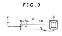
- an image signal is transmitted by radio communication from the receiver apparatus 50 provided separately from the thin image display apparatus body 1 as seen in FIGS. 9 and 10 to the thin image display apparatus body 1.
- the receiver apparatus 50 is provided separately from the thin image display apparatus body 1 while a driving display circuit 51 is provided in the thin image display apparatus body 1.
- the receiver apparatus 50 includes a reception signal input terminal 50a to which a reception signal, for example, from a digital broadcast receiving antenna 52 is supplied, a network terminal 50b to which an image signal is supplied from the outside, and an antenna terminal 50c to which a radio outputting antenna 53 is connected.
- a reception signal received by the digital broadcast receiving antenna 52 is supplied to a digital demodulating tuner 54, by which the reception signal is converted into an MPEG-TS stream.
- the MPEG-TS stream is supplied to an MPEG decoder 55, and an image signal obtained by the MPEG decoder 55 is supplied to an image signal processing circuit 56.
- the image signal is subject to various signal processes by the image signal processing circuit 56 and is then supplied to a graphic production synthesis circuit 57.
- the graphic production synthesis circuit 57 produces a graphic screen in response to an operation of the thin image display apparatus in accordance with a command from a CPU 58.
- the graphic production synthesis circuit 57 superposes or replaces the graphic screen on or with the image signal and supplies a resulting signal to an image compression circuit 59.
- the image compression circuit 59 compresses the image signal received from the graphic production synthesis circuit 57 with a codec suitable for a frequency band for transmission and supplies the compressed image signal to a multiplexing/modulation circuit 60.
- a sound signal is supplied from the MPEG decoder 55 to a sound signal processing circuit 61 while a sound signal from an internal bus 62 is supplied to the sound signal processing circuit 61 through a sound decoder 63.
- the sound signal is subject to various signal processes by the sound signal processing circuit 61 and is then supplied to the multiplexing/modulation circuit 60.
- the compressed image signal and the sound signal are synthesized and modulated by the multiplexing/modulation circuit 60 and then supplied to the radio outputting antenna 53 so that they are transmitted by radio transmission.
- the CPU 58 takes charge of control of the thin image display apparatus, and software necessary for the control by the CPU 58 is stored in a ROM 64. Further, a RAM 65 for allowing the CPU 58 to execute the software is provided.
- the CPU 58, ROM 64 and RAM 65 are connected to each other by the internal bus 62.
- An external signal from the network terminal 50b is supplied to the internal bus 62 through an Ethernet I/F 66. Further, a remote control signal from a remote commander 67 is supplied to a remote control light reception section 68 and then supplied from the remote control light reception section 68 to the CPU 58 so that the receiver apparatus 50 is remotely controlled by the remote commander 67.
- the driving display circuit 51 provided in the thin image display apparatus body 1 of the present thin image display apparatus receives, at any of the radio antennas 15a, 15b and 15c thereof, a transmission signal transmitted from the radio outputting antenna 53.
- the reception signal received by the radio antenna 15a, 15b or 15c is supplied to a demodulation/demultiplexing section 70.
- the demodulation/demultiplexing section 70 demodulates the reception signal and demultiplexes it into an image signal and a sound signal.
- the image signal obtained by the demodulation/demultiplexing section 70 is supplied to a panel driving circuit 71.
- the panel driving circuit 71 converts the image signal into a signal necessary for the image display section 1a of the thin image display apparatus body 1 and supplies the signal to the image display section 1a so that an image is displayed by the image display section 1a.
- the sound signal obtained by the demodulation/demultiplexing section 70 is supplied to a speaker 73 through a sound amplification circuit 72 so that sound is outputted from the speaker 73.
- the thin image display apparatus power is supplied to the thin image display apparatus body 1 through the power lines 11a and 11b disposed in the inside of the support member 6 while an image signal is supplied by radio communication to the thin image display apparatus body 1. Consequently, the wiring lines do not become apparently miscellaneous, and the thin image display apparatus can be installed while keeping a fine appearance.
- an image signal is supplied by radio communication to the thin image display apparatus body 1 from the receiver apparatus 50 provided separately from the thin image display apparatus body 1. Therefore, there is no restriction to the wiring. Further, the digital broadcast receiving antenna 52, radio outputting antenna 53 and radio antennas 15a, 15b and 15c can be placed at positions at which they exhibit a high sensitivity. Consequently, there is no disadvantage of failure of reception of an image signal, and there is no restriction to the arrangement location of the thin image display apparatus body 1.
- the plug 9 provided at one end of the support member 6 is mechanically secured to the ceiling rosette 8 provided on the ceiling 5, the plug 9 may otherwise be attached directly to a wiring duct rail 12 for illumination or through an adapter 13 combined therewith.
- the plug 9 provided at one end of the support member 6 is mechanically secured directly and electrically connected to a wiring duct rail 12 for illumination suspended from the ceiling rosette 8 of the ceiling 5.
- the plug 9 may be mechanically secured and electrically connected to the wiring duct rail 12 for illumination through the adapter 13 combined with the plug 9 as seen in FIG. 11B.
- an illumination apparatus 14 is mechanically secured and electrically connected to the wiring duct rail 12 for illumination.
- the wiring duct rail 12 for illumination may be secured to a ceiling portion inclined face 5a while the plug 9 provided at one end of the support member 6 is mechanically secured and electrically connected to the wiring duct rail 12.
- the wiring duct rail 12 for illumination may be secured' to a vertical wall face 5b while the plug 9 provided at one end of the support member 6 is mechanically secured and electrically connected to the wiring duct rail 12.
- the support member 6 does not necessarily have to be disposed vertically although it depends upon the length and the strength of the support member 6, the weight of the thin image display apparatus body 1 and the wiring duct rail 12 (refer to the arrangements of FIGS. 12 and 13).
- the rocking mechanism 7 may be adjusted to an angle at which the lower end of the thin image display apparatus body 1 is held by the wall face 5b so that the force to be applied to be wiring duct rail 12 may be reduced.
- the rocking mechanism 7 may otherwise be mounted for movement also in a vertical direction on the support member 6 or may be formed from a universal joint.
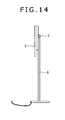
- the thin image display apparatus body 1 is suspended on the ceiling 5 or the wall face 5b by means of the support member 6, the thin image display apparatus body 1 may otherwise be supported in a stand-like fashion by means of the support member 6 as seen in FIG. 14. Except this, the thin image display apparatus of the arrangement of FIG. 14 is configured similarly to the thin image display apparatus described hereinabove with reference to FIGS. 1A to 7 or FIGS. 8A to 10. Also with the thin image display apparatus of FIG. 14, similar advantages to those of the thin image display apparatus of FIGS. 1A to 7 or FIGS. 8A to 10 can be achieved.
Landscapes
- Engineering & Computer Science (AREA)
- General Engineering & Computer Science (AREA)
- Signal Processing (AREA)
- Multimedia (AREA)
- Mechanical Engineering (AREA)
- Power Engineering (AREA)
- Computer Networks & Wireless Communication (AREA)
- Devices For Indicating Variable Information By Combining Individual Elements (AREA)
Applications Claiming Priority (1)
| Application Number | Priority Date | Filing Date | Title |
|---|---|---|---|
| JP2006105712A JP2007279397A (ja) | 2006-04-06 | 2006-04-06 | 薄型映像表示装置 |
Publications (2)
| Publication Number | Publication Date |
|---|---|
| EP1843579A2 true EP1843579A2 (de) | 2007-10-10 |
| EP1843579A3 EP1843579A3 (de) | 2009-02-18 |
Family
ID=38283220
Family Applications (1)
| Application Number | Title | Priority Date | Filing Date |
|---|---|---|---|
| EP07251380A Withdrawn EP1843579A3 (de) | 2006-04-06 | 2007-03-29 | Dünne Bildanzeigevorrichtung |
Country Status (6)
| Country | Link |
|---|---|
| US (1) | US7876315B2 (de) |
| EP (1) | EP1843579A3 (de) |
| JP (1) | JP2007279397A (de) |
| KR (1) | KR20070100147A (de) |
| CN (1) | CN101051429A (de) |
| TW (1) | TW200746817A (de) |
Families Citing this family (10)
| Publication number | Priority date | Publication date | Assignee | Title |
|---|---|---|---|---|
| EP2210664A4 (de) | 2007-10-26 | 2011-12-21 | Asahi Kasei Chemicals Corp | Verbundpartikelbeladener artikel, verfahren zur herstellung des verbundpartikelbeladenen artikels und verfahren zur herstellung der verbindung anhand des verbundpartikelbeladenen artikels als chemischer synthesekatalysator |
| KR100955480B1 (ko) * | 2009-03-12 | 2010-04-30 | 삼성전자주식회사 | 디스플레이장치용 지지장치 및 이를 포함하는 디스플레이장치 |
| US8109647B2 (en) | 2009-07-28 | 2012-02-07 | Lg Innotek Co., Ltd. | Lighting device |
| TWI398811B (zh) * | 2009-07-30 | 2013-06-11 | Asustek Comp Inc | 顯示系統 |
| US8511486B2 (en) * | 2010-01-22 | 2013-08-20 | Todd Mansor | Overhead rack storage system |
| JP5617626B2 (ja) * | 2010-12-28 | 2014-11-05 | ソニー株式会社 | 表示装置 |
| US9240160B2 (en) | 2013-02-18 | 2016-01-19 | Au Optronics Corporation | Driving circuit and display device of using same |
| KR101724068B1 (ko) * | 2017-01-24 | 2017-04-06 | 주식회사 탑시스템 | 천장형 디스플레이 위치 조절장치 |
| KR102374561B1 (ko) * | 2017-06-19 | 2022-03-15 | 삼성디스플레이 주식회사 | 표시 장치 및 입력감지부재 |
| JP7079136B2 (ja) * | 2018-05-07 | 2022-06-01 | 株式会社遠藤照明 | 配線ダクト取付型ディスプレイ |
Citations (1)
| Publication number | Priority date | Publication date | Assignee | Title |
|---|---|---|---|---|
| US20050105012A1 (en) * | 2003-10-28 | 2005-05-19 | Kim Sung K. | Display |
Family Cites Families (18)
| Publication number | Priority date | Publication date | Assignee | Title |
|---|---|---|---|---|
| DE4033419A1 (de) | 1990-10-20 | 1992-04-23 | Wolman Gmbh Dr | Polymere stickstoffverbindungen und metall fixierende saeuren enthaltende holzschutzmittel |
| JPH1079902A (ja) | 1996-09-04 | 1998-03-24 | Toshiba Corp | 透過型プロジェクションテレビ受像機の筺体 |
| US6677936B2 (en) * | 1996-10-31 | 2004-01-13 | Kopin Corporation | Color display system for a camera |
| JPH10293543A (ja) | 1997-04-18 | 1998-11-04 | Fujitsu General Ltd | 平面表示装置の取付装置 |
| US6104443A (en) * | 1998-12-30 | 2000-08-15 | Adcock; David | Suspended television and video monitor |
| DE20023673U1 (de) * | 1999-06-21 | 2005-07-21 | Holliger, Thomas | Befestigungsvorrichtung |
| US6377223B1 (en) * | 1999-11-11 | 2002-04-23 | Ge Medical Systems Information Technologies, Inc. | Portable patient monitor with antenna integrated into handle |
| JP2002032033A (ja) | 2000-07-19 | 2002-01-31 | Fujitsu General Ltd | 表示装置の吊下装置 |
| JP2002064765A (ja) | 2000-08-23 | 2002-02-28 | Funai Electric Co Ltd | テレビジョンにおける内蔵アンテナの取付構造 |
| JP4815701B2 (ja) | 2001-06-28 | 2011-11-16 | パナソニック株式会社 | テレビ信号配信装置 |
| JP4142428B2 (ja) | 2002-12-26 | 2008-09-03 | シャープ株式会社 | 平面表示装置 |
| US20040237113A1 (en) * | 2003-05-19 | 2004-11-25 | Taicom Data Systems Co., Ltd. | Plug-and-play video transmitting device |
| US7171506B2 (en) * | 2003-11-17 | 2007-01-30 | Sony Corporation | Plural interfaces in home network with first component having a first host bus width and second component having second bus width |
| JP2005221653A (ja) * | 2004-02-04 | 2005-08-18 | Os Co Ltd | 映像表示装置の吊り下げ装置 |
| JP4067510B2 (ja) | 2004-03-31 | 2008-03-26 | シャープ株式会社 | テレビジョン受信装置 |
| CN1750634A (zh) * | 2004-09-13 | 2006-03-22 | 乐金电子(昆山)电脑有限公司 | 利用家庭网络的无线电视系统 |
| DE202004018366U1 (de) * | 2004-11-26 | 2005-02-17 | Rechnet Gmbh | Modulares Befestigungssystem für Ein-/Ausgabegeräte |
| DE202005011344U1 (de) * | 2005-07-15 | 2005-12-08 | Ahrenholtz, Horst-Dieter, Dipl.-Ing. | Aufnahmechassis für Flachbildschirme mit integrierter Funkantenne und Anschluss für Deckenbeleuchtung |
-
2006
- 2006-04-06 JP JP2006105712A patent/JP2007279397A/ja active Pending
-
2007
- 2007-03-27 TW TW096110609A patent/TW200746817A/zh unknown
- 2007-03-29 EP EP07251380A patent/EP1843579A3/de not_active Withdrawn
- 2007-04-05 KR KR1020070033656A patent/KR20070100147A/ko not_active Ceased
- 2007-04-05 US US11/730,951 patent/US7876315B2/en not_active Expired - Fee Related
- 2007-04-06 CN CNA2007100908257A patent/CN101051429A/zh active Pending
Patent Citations (1)
| Publication number | Priority date | Publication date | Assignee | Title |
|---|---|---|---|---|
| US20050105012A1 (en) * | 2003-10-28 | 2005-05-19 | Kim Sung K. | Display |
Also Published As
| Publication number | Publication date |
|---|---|
| TW200746817A (en) | 2007-12-16 |
| KR20070100147A (ko) | 2007-10-10 |
| JP2007279397A (ja) | 2007-10-25 |
| US7876315B2 (en) | 2011-01-25 |
| US20070247452A1 (en) | 2007-10-25 |
| EP1843579A3 (de) | 2009-02-18 |
| CN101051429A (zh) | 2007-10-10 |
Similar Documents
| Publication | Publication Date | Title |
|---|---|---|
| US7876315B2 (en) | Thin image display apparatus | |
| US10957966B2 (en) | Wall mount for screens with an integrated antenna | |
| WO2009120324A3 (en) | Arc fault root-cause finder system and method | |
| CN102217302A (zh) | 用于网络tv的嵌入式无线天线 | |
| CN110249480B (zh) | 埋入型器具 | |
| US9559474B2 (en) | Track transmission system and track transmission device thereof | |
| CN111638638A (zh) | 腕戴式装置 | |
| US10027173B2 (en) | Powered security camera tool-free installation | |
| KR20080018059A (ko) | 무선안테나모듈 및 이를 갖춘 디스플레이장치 및디스플레이시스템 | |
| JP2009104493A (ja) | 光電式分離型感知器 | |
| KR200446161Y1 (ko) | 차량용 블루투스 핸즈프리 내장형 마이크 어셈블리 | |
| JP2011025850A (ja) | 車載用放送受信システム及び該システムを備える自動車 | |
| KR20060017061A (ko) | 디스플레이장치 | |
| CN209505606U (zh) | 一种车载支架发射器 | |
| JP2008244932A (ja) | 薄型テレビジョン | |
| KR200413161Y1 (ko) | 차량용 거치대 | |
| US9967990B2 (en) | Electronic apparatus | |
| KR20140033984A (ko) | 전력선을 이용한 차량용 통신 시스템 | |
| US10530039B1 (en) | Antenna extension device | |
| JP2012048930A (ja) | 合成分波回路内蔵コネクタおよび信号経路システム | |
| CN205664068U (zh) | 一种电视机安装支架 | |
| KR102655453B1 (ko) | 태블릿 착탈식 주방 티브이 시스템 | |
| US20090167620A1 (en) | Accessory-type antenna for vehicle | |
| CN223390759U (zh) | 一种车载天线 | |
| CN213777217U (zh) | 云台组件 |
Legal Events
| Date | Code | Title | Description |
|---|---|---|---|
| PUAI | Public reference made under article 153(3) epc to a published international application that has entered the european phase |
Free format text: ORIGINAL CODE: 0009012 |
|
| 17P | Request for examination filed |
Effective date: 20070412 |
|
| AK | Designated contracting states |
Kind code of ref document: A2 Designated state(s): AT BE BG CH CY CZ DE DK EE ES FI FR GB GR HU IE IS IT LI LT LU LV MC MT NL PL PT RO SE SI SK TR |
|
| AX | Request for extension of the european patent |
Extension state: AL BA HR MK YU |
|
| PUAL | Search report despatched |
Free format text: ORIGINAL CODE: 0009013 |
|
| AK | Designated contracting states |
Kind code of ref document: A3 Designated state(s): AT BE BG CH CY CZ DE DK EE ES FI FR GB GR HU IE IS IT LI LT LU LV MC MT NL PL PT RO SE SI SK TR |
|
| AX | Request for extension of the european patent |
Extension state: AL BA HR MK RS |
|
| 17Q | First examination report despatched |
Effective date: 20090406 |
|
| AKX | Designation fees paid |
Designated state(s): DE FR GB |
|
| STAA | Information on the status of an ep patent application or granted ep patent |
Free format text: STATUS: THE APPLICATION IS DEEMED TO BE WITHDRAWN |
|
| 18D | Application deemed to be withdrawn |
Effective date: 20130822 |