EP1844689A2 - Système d'installation de baignoire pour une baignoire pourvue d'une installation tourbillonnaire - Google Patents
Système d'installation de baignoire pour une baignoire pourvue d'une installation tourbillonnaire Download PDFInfo
- Publication number
- EP1844689A2 EP1844689A2 EP07105762A EP07105762A EP1844689A2 EP 1844689 A2 EP1844689 A2 EP 1844689A2 EP 07105762 A EP07105762 A EP 07105762A EP 07105762 A EP07105762 A EP 07105762A EP 1844689 A2 EP1844689 A2 EP 1844689A2
- Authority
- EP
- European Patent Office
- Prior art keywords
- bottom plate
- support profiles
- substructure
- elements
- sound
- Prior art date
- Legal status (The legal status is an assumption and is not a legal conclusion. Google has not performed a legal analysis and makes no representation as to the accuracy of the status listed.)
- Withdrawn
Links
Images




Classifications
-
- A—HUMAN NECESSITIES
- A47—FURNITURE; DOMESTIC ARTICLES OR APPLIANCES; COFFEE MILLS; SPICE MILLS; SUCTION CLEANERS IN GENERAL
- A47K—SANITARY EQUIPMENT; ACCESSORIES THEREFOR, e.g. TOILET ACCESSORIES
- A47K3/00—Baths; Showers; Appurtenances therefor
- A47K3/16—Devices for fastening baths to floors or walls; Adjustable bath feet ; Lining panels or attachments therefor
-
- A—HUMAN NECESSITIES
- A61—MEDICAL OR VETERINARY SCIENCE; HYGIENE
- A61H—PHYSICAL THERAPY APPARATUS, e.g. DEVICES FOR LOCATING OR STIMULATING REFLEX POINTS IN THE BODY; ARTIFICIAL RESPIRATION; MASSAGE; BATHING DEVICES FOR SPECIAL THERAPEUTIC OR HYGIENIC PURPOSES OR SPECIFIC PARTS OF THE BODY
- A61H33/00—Bathing devices for special therapeutic or hygienic purposes
- A61H33/0087—Therapeutic baths with agitated or circulated water
-
- A—HUMAN NECESSITIES
- A61—MEDICAL OR VETERINARY SCIENCE; HYGIENE
- A61H—PHYSICAL THERAPY APPARATUS, e.g. DEVICES FOR LOCATING OR STIMULATING REFLEX POINTS IN THE BODY; ARTIFICIAL RESPIRATION; MASSAGE; BATHING DEVICES FOR SPECIAL THERAPEUTIC OR HYGIENIC PURPOSES OR SPECIFIC PARTS OF THE BODY
- A61H2201/00—Characteristics of apparatus not provided for in the preceding codes
- A61H2201/01—Constructive details
- A61H2201/0165—Damping, vibration related features
- A61H2201/0169—Noise reduction
Definitions
- the invention relates to a tub installation system for a (bath) equipped with a whirl device according to the preamble of claim 1.
- the covering device according to the EP 1 175 861 B1 has a laterally over the tub projecting bottom plate.
- vertical support struts are arranged with mutual lateral distances.
- the vertical support struts are each mounted in a corner region of the bottom plate.
- a cross strut is attached, which is provided with supports for a ledge.
- the vertical support struts are formed by profile pieces.
- cover plates are arranged outside via intermediate links.
- the bathtub is surrounded on the side and bottom by a sound insulation layer.
- the insulation layer consists essentially of a softening material.
- the bathtub is supported by intermediate links on the bottom plate.
- the vertical arranged cover plates are finally pasted from the outside with ceramic plates or the like.
- the covering device described above is intended only to disguise a whirl device with ceramic or stone slabs. However, it does not offer a solution that satisfies the aesthetic and, above all, noise requirements of some building owners.
- a whirl-effect bathtub Compared to a conventional shuttering of a bathtub, a whirl-effect bathtub must absorb much more sound and vibration. To damp these emissions, measures are therefore needed to absorb, dampen and decouple the sound and vibrations.
- the tub itself which also vibrates through the hoses, pumps and pipes, must also be isolated from the masonry or building.
- a device for installing a bath equipped with a whirl device (bath) tub or sanitary device of the type mentioned by the features of the characterizing part of patent claim 1 is characterized.
- a tub installation system for a whirlpool bath or other sanitary facility (e.g., a pool) equipped with a whirl facility.
- a tray installation system on the one hand in the sense of storage or suspension and on the other hand in the sense of a panel, for the tub used.
- the tray installation system comprises a bottom plate.
- the bottom plate is provided on its side facing the bathtub wholly or partially with an insulating, in particular sound waves absorbing pad.
- an edge region of the bottom plate supporting profiles are attached.
- the support profiles are arranged at a lateral distance from each other and are inclined in most cases (for example, the conical covering of trays).
- the tray installation system further comprises a peripheral frame which is attached to the support profiles and serves as a supporting substructure together with the support profiles and the bottom sheet.
- the surrounding frame is at least partially covered with sound-absorbing material, on which the bathtub rests with a supporting area.
- the substructure is clad with apron-shaped cladding elements.
- the cladding elements are preferably attached to the support profiles with non-visible (ie hidden or invisible) fasteners.
- the fasteners are fastened adjustable, for example, to the support profiles.
- the apron-shaped cladding elements preferably have an outer shape which approximates or is modeled on the shape of the band tray (eg a conically tapering shape).
- This new and inventive approach has the advantage that, due to the many shapes and colors in which whirlpool baths are offered and the variety of architectural possibilities available for incorporating a whirl facility in a room, the whirlpool Interior can be disguised individually.
- it is possible to install surface-finished tub skirt parts only in the final finishing or construction phase, in order to avoid damage to these surfaces. Large and smooth cladding surfaces are possible, which are very aesthetic and easy to clean.
- the casing of the surrounding frame which is present at least in the support area between the surrounding frame and the bath, it is prevented that vibrations of the whirl device are transferred to the substructure and from there to the building.
- the cladding of the substructure allows the entire whirlpool bathtub to be integrated aesthetically pleasing into the room. This is particularly because the cladding elements are attached to the support profiles with not visible from the outside fasteners.
- the tub can also be mounted on a wall or in a niche.
- the whirl device can be well protected against manipulation by laymen or during other work on the construction, since the access to the various pumps, motors and lines only a specialist is possible.
- interstices which are formed by the distances of the support profiles, preferably insulating panels or elements are attached. These are connected via intermediate links with the support profiles and close the gaps, so that the propagation of noise to the environment of the whirlpool device can be prevented.
- the present invention is particularly well suited for dressing and wearing freestanding whirlpool baths.
- the bottom plate has the shape of an approximate surface projection of the bathtub and the support profiles take a direct connection between the bottom plate and the peripheral frame that means, the support profiles are preferably inclined to the bottom plate.
- the support profiles are preferably inclined to the bottom plate.
- the bathtub is hung in the substructure in the surrounding frame, and with intermediate links (in the form of feet) additionally supported on the bottom plate.
- intermediate links in the form of feet
- the invention can also be used for baths that have no feet.
- the tub is suspended "floating" in the surrounding frame. This leads to a further improvement of the sound decoupling.
- the "floating" suspension also has advantages for installation in high-rise buildings that are unstable, or for use in earthquake-prone areas, to prevent excessive vibration of the bathtub.
- the peripheral frame 12 advantageously has a tubular cross-section (but there are other forms conceivable) and is connected via sound-insulating elements with the support profiles.
- a tubular cross-section allows an optimal support surface opposite the edge of the bathtub.
- the cladding elements advantageously consist of prefabricated elements made of wood, mineral fibers, plastic, glass, and / or metal.
- the fastening elements are preferably fastened with a quick-clamping means or a clamping means on the support profiles from the inside of the substructure ago. This allows the panel to be mounted quickly, easily and aesthetically pleasing on site.
- the paneling can be mounted at any time after installing the tub, ie at a later date. It may be disassembled for refreshment or maintenance purposes or replaced with other aprons.
- FIG. 1 A first embodiment of the invention is shown in FIG. 1 and in FIG.
- a stable (tub) installation system 10 is used to support the bath or the sanitary device on the one hand and to serve as a scaffolding for the sound-insulating attachments or attachments and to support the covering on the other hand. All these aspects must be considered in order to be able to realize an insulation which corresponds to today's requirements and at the same time has an aesthetic appearance.
- the tray installation system 10 is according to the invention designed so that the bath 11 is used when installed from above into the tub installation system 10 and the tub 11 then wholly or partially wears.
- the tray installation system 10 has a bottom plate 15 and a plurality of laterally spaced support profiles 14.
- a peripheral frame 12 is provided in the upper region of the mounting system 10, which is attached at least to a part of the support profiles 14.
- the current frame 12 is used together with the support profiles 14 and the bottom plate 15 as a substructure or support structure for the tub 11th
- the bottom plate 15 is provided on one of the bath 11 facing upper side completely or partially with an insulating, in particular sound waves absorbing pad 16.
- the peripheral frame 12 is at least partially covered with sound-absorbing material 12.1 (see, for example, Fig. 3A or 3b), and the bath 11 rests with a support area 11.1 on this material 12.1.
- the entire substructure is now disguised according to the invention with apron-shaped cladding elements 13, which can be seen in Fig. 1 right and left of the pan 11 only in section.
- the cladding elements 13 are preferably fastened to the support profiles 14 with fastening elements which are not visible from the outside. In order to adjust the cladding elements 13 after assembly, adjustable fasteners 30 are used.
- FIGS. 3A and 3B Two different embodiments of a partial aspect of installation systems 10 according to the invention are shown in FIGS. 3A and 3B.
- Fig. 3A and 3B Two different embodiments of a partial aspect of installation systems 10 according to the invention are shown in FIGS. 3A and 3B.
- FIG. 3A shows a section through the cladding element 13, the inner support profile 14 and the insulating board 19 or element attached thereto.
- the tube of the peripheral frame 12 is screwed, glued or welded.
- sound-absorbing intermediate elements 14.1 are used.
- the frame 12 is at least partially encased with a sound-insulating material 12.1. This measure also serves for sound decoupling.
- Fig. 3A can be seen a part of the upper "collar" of a bath 11.
- the bath 11 is inserted into the tub installation system 10 such that a support area 11.1 of the tub 11 rests on the sound-insulating material 12.1 in the inner area of the collar.
- cladding element 13 has a different shape.
- a support profile 14 is shown, which rests at the lower end on the bottom plate 15 and is connected at the upper end to the peripheral frame 12.
- the support profile 14 may have at the lower end a plate 14.2 or an angle to allow attachment to or on the bottom plate 15. Also in this area are preferably sound-absorbing materials used to prevent sound bridges.
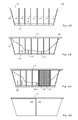
- FIGS. 4A to 4D A mounting method according to the invention will be explained with reference to FIGS. 4A to 4D.
- Fig. 4A the assembled mounting system 10 is shown.
- This installation system 10 can be prefabricated in a factory and made as a whole to the site.
- the sound-insulating material 12.1 on has been mounted to the current frame 12 (not visible in Fig. 4B)
- the bath 11 is lowered from above into the frame.
- support elements 17 for example in the form of feet
- a portion of the weight of the pan 11 is also absorbed by the frame 12 and introduced via the support sections 14 in the bottom plate 15 in the illustrated embodiment at several points on the bottom plate 15.
- Students die Elements 17 drum die Tanne 11 in den Bodenplatte 15 loom.
- preassembled base are provided on the bottom plate 15, which were already mounted prior to assembly of the tub 11 at the exact correct position. These pedestals can then receive the support elements 17 (eg in the form of feet) of the tub 11. If a tub 11 without support elements (eg in the form of feet) is used, there is no need for such a base, or the like.
- Fig. 4C is indicated schematically that now the whirl components 20 installed and the sanitary connections (for example, with a tub outlet 20.1 and other sanitary elements) can be created. Then insulation boards 19 are mounted in the spaces between the support sections 14 in the illustrated embodiment. In Fig. 4C, two of these plates 19 are already mounted. The last step is now the mounting of the cladding elements 13, which are designed aprons. In the embodiment shown in FIG. 4D, two shell-shaped or apron-shaped cladding elements 13 are used, which are respectively pushed onto the tray installation system 10 from the right and from the left. It can be used according to the invention one-piece and multi-part and single or multi-layer Schurzensysteme.
- the plates 19 indicated in FIG. 4C serve, inter alia, to protect against damage or tampering of all kinds during the further construction phases. After the plates 19 have been fitted, the shell of the bathtub is ready.
- the trim elements 13 are preferably prefabricated elements, as shown in Fig. 4D. Particularly preferred are 2- or 3-dimensionally curved wooden elements, which are composed of several layers.
- the cladding elements 13 may be ground outside and painted or veneered. Particularly suitable are trim elements 13 which are finished with coverings such as glass, plastic or metal. Wood or wood fiber products and cladding elements 13 with a multilayer structure are very particularly preferred, as can be seen in FIG. 7 at the cross-section of the cladding element 13.
- the trim elements 13 can be removed at any time to protect against contamination or damage, the "inner workings" of the mounting system continue to be protected by the plates 19.
- the trim elements 13 are preferably supported only by the support profiles 14 and do not touch the floor 1, i. the cladding elements 13 are suspended suspended. This also serves for better sound decoupling.
- the cladding preferably traces the shape of the tub 11.
- the bottom plate 15 has approximately the shape of a surface projection of the bath 11.
- the tub has an oval shape (see, e.g., Fig. 2)
- the bottom plate 15 has this shape.
- the support profiles 14 are arranged along the outer periphery of the bottom plate 15 and connect the outer circumference directly (i.e., in a straight line) or in a curved shape with the peripheral frame 12.
- a tube with a tubular cross-section serves as a peripheral frame 12, as already described.
- the frame can consist of several be made in nested or interconnected pieces of pipe.
- the peripheral frame 12 may also have a different cross-section.
- a handrail 21 is attached to the frame 12, as indicated in FIG. 5 or 11.
- handrails 21 are used to enable one hand, a safe climbing and leaving the bathtub 11.
- towels or the like can be hung up thereon.
- the attachment of such handrails has been very expensive.
- a handrail 21 is plugged or screwed onto the frame 12 by means of connecting elements 21.1. This can provide a very stable handrail 21 which is very safe.
- FIG. 6 another mounting system 10 with trough 11 is shown. Based on this figure is merely explained how flexible the invention can be used.
- the cladding elements 13 can assume almost any desired shape.
- a fastener 30 which serves for attaching and adjusting a cladding element 13 on a support profile 14.
- the fastening and the adjustment takes place from the inside of the substructure.
- the fastening element 30 comprises a quick-clamping means 24, 25, which is fastened in the support profile 14. It is a screw 23 (eg with hexagonal head) inserted from the inside through a cylindrical opening of the quick clamping means 24, 25, wherein the threaded end of the screw 23 in a nut 22 (for example, an insert or Einschraubmutter) engages in the back of the Cladding element 13 sits.
- the screw 23 together with the cladding element 13 attached thereto can now be displaced in a longitudinal hole of the support profile until the ideal position of the cladding element 13 is reached. Then, by tightening the element 25 of the quick clamping means, the screw 25 can be clamped. Of the Distance between the plate 19 and the cladding element 13 can be done by a pure or rough screw of the screw 23.
- FIG. 8 another embodiment of a fastener 30 is shown adapted for attaching and adjusting a trim element 13 to a rear portion (e.g., a box with fittings 18).
- the fastening and the adjustment takes place from the inside of the substructure, i. also this fastener 30 is hidden, i. not visible from the outside.
- the box with fittings 18 has a side wall 18.1, which is fixed to a support section 14.
- threaded pin 33 is provided (fixed).
- the cladding element 13 with attached threaded pin 33 is pushed to the side wall 18.1 and the set screw 33 is passed through a (long) hole until it is visible from the inside.
- washers 34 and a nut 35 are used to screw the threaded pin 33 together with cladding element 13 on the side wall 18.1.
- the distance between the side wall 18.1 and cladding element 13 can be adjusted. If the set screw 33 is in a slot, the position can also be changed by moving it, before the nut 35 is then tightened.
- FIG. 9 shows a further embodiment of a fastening element 30, which serves for fastening and adjusting two trim element 13 on a support profile 14.
- the fastening and the adjustment takes place from the inside of the substructure.
- a metal plate 37 is attached on the curved cladding element 13. The attachment can be done by gluing or for example by a screw 36.
- a (long) hole is provided in the metal plate 37 and / or the support profile 14 a (long) hole is provided.
- On the support section 14 (eg on the inside) is a screw-in or drive nut 32 and it is a screw 23 from the outside through the metal plate 37 and the support section 14 is screwed.
- the curved cladding element 13 can now be moved together with metal plate 37 until it assumes the ideal position.
- the straight cladding element 13 is attached. This is done in the example shown by a magnet 39 adheres to the inside of the element 13 on the metal plate 37.
- a recess 13.1 may be provided on the inside of the element 13. Due to the magnetic connection and the second cladding element 13 can be used and attached exactly.
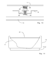
- Fig. 10 shows an embodiment of a setting means for moving / adjusting the mounting position of the bath 11.
- the setting means may be arranged on one or more support profiles 14 or on the peripheral frame 12. It comprises a set screw 43, which is screwed into a rivet nut 44 or the like. At the end of the screw sits a rubber buffer 46 or an equivalent means that presses against a portion of the bath 11 when the screw 43 is screwed in further.
- a damping or spring element 43 is provided to bias the rubber buffer 46 in the direction of the bath 11.
- cladding elements 13 can assume almost any shape.
- the cladding element 13 has a stepped or recessed base area 13.2.
Landscapes
- Health & Medical Sciences (AREA)
- Public Health (AREA)
- Epidemiology (AREA)
- General Health & Medical Sciences (AREA)
- Pain & Pain Management (AREA)
- Physical Education & Sports Medicine (AREA)
- Rehabilitation Therapy (AREA)
- Life Sciences & Earth Sciences (AREA)
- Animal Behavior & Ethology (AREA)
- Veterinary Medicine (AREA)
- Devices For Medical Bathing And Washing (AREA)
Applications Claiming Priority (1)
| Application Number | Priority Date | Filing Date | Title |
|---|---|---|---|
| CH5842006 | 2006-04-10 |
Publications (2)
| Publication Number | Publication Date |
|---|---|
| EP1844689A2 true EP1844689A2 (fr) | 2007-10-17 |
| EP1844689A3 EP1844689A3 (fr) | 2013-12-18 |
Family
ID=38179553
Family Applications (1)
| Application Number | Title | Priority Date | Filing Date |
|---|---|---|---|
| EP07105762.4A Withdrawn EP1844689A3 (fr) | 2006-04-10 | 2007-04-05 | Système d'installation de baignoire pour une baignoire pourvue d'une installation tourbillonnaire |
Country Status (1)
| Country | Link |
|---|---|
| EP (1) | EP1844689A3 (fr) |
Family Cites Families (4)
| Publication number | Priority date | Publication date | Assignee | Title |
|---|---|---|---|---|
| DE2353526A1 (de) * | 1972-10-30 | 1974-05-09 | Otto Dr Trenner | Montagevorrichtung fuer badewannen |
| DE29706518U1 (de) * | 1997-04-11 | 1997-05-22 | E. Missel GmbH & Co., 70374 Stuttgart | Trägersystem für Bade-, Dusch- oder Whirlwannen |
| DE20105503U1 (de) * | 2000-07-25 | 2001-06-13 | Gassmann, Alfred, Udligenswil | Konstruktionsprofile für die Verkleidung von Sanitäreinrichtungen |
| DE20302187U1 (de) * | 2002-10-30 | 2004-03-11 | Walsdorf, Ulrich | Verkleidung für Bade- und Brausewannen, insbesondere für Whirlpools |
-
2007
- 2007-04-05 EP EP07105762.4A patent/EP1844689A3/fr not_active Withdrawn
Also Published As
| Publication number | Publication date |
|---|---|
| EP1844689A3 (fr) | 2013-12-18 |
Similar Documents
| Publication | Publication Date | Title |
|---|---|---|
| EP3527731B1 (fr) | Module de paroi sanitaire et procédé de construction d'une paroi sanitaire | |
| EP2333174B1 (fr) | Système d'écoulement de douche | |
| EP2354341A2 (fr) | Goulotte dotée d'un recouvrement réglable en hauteur | |
| DE3440545C2 (fr) | ||
| DE3320617C2 (de) | Vorgefertigte Verkleidungsschürze für Badewannen | |
| DE29706518U1 (de) | Trägersystem für Bade-, Dusch- oder Whirlwannen | |
| DE102011051739B4 (de) | Montageeinheit für eine Unterputz-Sanitärarmatur | |
| DE102006026707B4 (de) | Duschwanne | |
| EP2182140B1 (fr) | Kit destiné à une cellule sanitaire et cellule sanitaire correspondante | |
| DE102004049130A1 (de) | Duschwanne mit auf einem höhenverstellbaren Duschwannenträger aufsetzbarer Duschwannenschale | |
| EP0495238B1 (fr) | Ensemble d'éléments de construction pour douches rondes | |
| EP1245748B1 (fr) | Dispositif de support pour appareils sanitaires | |
| EP0723757A1 (fr) | Système de support pour baignoires ou bacs à douche | |
| DE3310084C1 (de) | Träger aus Kunststoff für Bade- und Brausewannen | |
| DE7602215U1 (de) | Installationskasten | |
| DE19538366A1 (de) | Nachträglich anbaubarer Balkon | |
| DE202009000882U1 (de) | Anordnung zum Setzen einer Duschtasse oder einer Badewanne | |
| DE10008433A1 (de) | Vorgefertigte Montage/Verkleidungselemente für Objekte und Einrichtungen, insbesondere in Sanitärbereichen | |
| EP2014206A1 (fr) | Dispositif de fixation d'une baignoire équipée d'une installation tourbillonnaire | |
| EP0116012B1 (fr) | Socle-élément préfabriqué pour baignoires et cuvettes de douches | |
| DE20300839U1 (de) | Unterbau für ein Hock-Klosett | |
| DE10013722A1 (de) | Bausatz für eine Vorwandinstallation | |
| EP1676511A1 (fr) | Installation de douche | |
| CH669510A5 (fr) | ||
| CH702378B1 (de) | Untergestell-Montagesatz für das Erstellen einer Sanitäreinrichtung, Sanitäreinrichtung und Verfahren zum Erstellen einer Sanitäreinrichtung. |
Legal Events
| Date | Code | Title | Description |
|---|---|---|---|
| PUAI | Public reference made under article 153(3) epc to a published international application that has entered the european phase |
Free format text: ORIGINAL CODE: 0009012 |
|
| AK | Designated contracting states |
Kind code of ref document: A2 Designated state(s): AT BE BG CH CY CZ DE DK EE ES FI FR GB GR HU IE IS IT LI LT LU LV MC MT NL PL PT RO SE SI SK TR |
|
| AX | Request for extension of the european patent |
Extension state: AL BA HR MK YU |
|
| PUAL | Search report despatched |
Free format text: ORIGINAL CODE: 0009013 |
|
| AK | Designated contracting states |
Kind code of ref document: A3 Designated state(s): AT BE BG CH CY CZ DE DK EE ES FI FR GB GR HU IE IS IT LI LT LU LV MC MT NL PL PT RO SE SI SK TR |
|
| AX | Request for extension of the european patent |
Extension state: AL BA HR MK RS |
|
| RIC1 | Information provided on ipc code assigned before grant |
Ipc: A47K 3/16 20060101AFI20131113BHEP Ipc: A61H 33/00 20060101ALI20131113BHEP |
|
| AKY | No designation fees paid | ||
| REG | Reference to a national code |
Ref country code: DE Ref legal event code: R108 |
|
| REG | Reference to a national code |
Ref country code: DE Ref legal event code: R108 Effective date: 20140827 |
|
| STAA | Information on the status of an ep patent application or granted ep patent |
Free format text: STATUS: THE APPLICATION IS DEEMED TO BE WITHDRAWN |
|
| 18D | Application deemed to be withdrawn |
Effective date: 20140619 |