EP2354341A2 - Goulotte dotée d'un recouvrement réglable en hauteur - Google Patents
Goulotte dotée d'un recouvrement réglable en hauteur Download PDFInfo
- Publication number
- EP2354341A2 EP2354341A2 EP11000830A EP11000830A EP2354341A2 EP 2354341 A2 EP2354341 A2 EP 2354341A2 EP 11000830 A EP11000830 A EP 11000830A EP 11000830 A EP11000830 A EP 11000830A EP 2354341 A2 EP2354341 A2 EP 2354341A2
- Authority
- EP
- European Patent Office
- Prior art keywords
- gutter
- bridge
- support surfaces
- cover plate
- approximately
- Prior art date
- Legal status (The legal status is an assumption and is not a legal conclusion. Google has not performed a legal analysis and makes no representation as to the accuracy of the status listed.)
- Granted
Links
Images


Classifications
-
- E—FIXED CONSTRUCTIONS
- E03—WATER SUPPLY; SEWERAGE
- E03F—SEWERS; CESSPOOLS
- E03F5/00—Sewerage structures
- E03F5/04—Gullies inlets, road sinks, floor drains with or without odour seals or sediment traps
- E03F5/06—Gully gratings
-
- E—FIXED CONSTRUCTIONS
- E03—WATER SUPPLY; SEWERAGE
- E03F—SEWERS; CESSPOOLS
- E03F5/00—Sewerage structures
- E03F5/04—Gullies inlets, road sinks, floor drains with or without odour seals or sediment traps
- E03F5/0407—Floor drains for indoor use
- E03F5/0408—Floor drains for indoor use specially adapted for showers
-
- E—FIXED CONSTRUCTIONS
- E03—WATER SUPPLY; SEWERAGE
- E03F—SEWERS; CESSPOOLS
- E03F5/00—Sewerage structures
- E03F5/04—Gullies inlets, road sinks, floor drains with or without odour seals or sediment traps
- E03F2005/0412—Gullies inlets, road sinks, floor drains with or without odour seals or sediment traps with means for adjusting their position with respect to the surrounding surface
- E03F2005/0413—Gullies inlets, road sinks, floor drains with or without odour seals or sediment traps with means for adjusting their position with respect to the surrounding surface for height adjustment
-
- Y—GENERAL TAGGING OF NEW TECHNOLOGICAL DEVELOPMENTS; GENERAL TAGGING OF CROSS-SECTIONAL TECHNOLOGIES SPANNING OVER SEVERAL SECTIONS OF THE IPC; TECHNICAL SUBJECTS COVERED BY FORMER USPC CROSS-REFERENCE ART COLLECTIONS [XRACs] AND DIGESTS
- Y02—TECHNOLOGIES OR APPLICATIONS FOR MITIGATION OR ADAPTATION AGAINST CLIMATE CHANGE
- Y02A—TECHNOLOGIES FOR ADAPTATION TO CLIMATE CHANGE
- Y02A30/00—Adapting or protecting infrastructure or their operation
- Y02A30/60—Planning or developing urban green infrastructure
Definitions
- the present invention relates to a gutter system, as it finds use in the sanitary and hydrotechnical field, in particular in the assembly or the production of prefabricated or created on-site Duschgesocilböden.
- Such gutter systems generally comprise a water-draining, trough-like channel or an approximately concave drainage channel and a cover which can be placed on or in the gutter and usually flush and flush with the shower floor.
- the gutters on either support frame or base, which provide an adaptable preferably by means of leveling screws in height support for the cover.
- the disadvantage here is that the support frame or - pedestals hinder the free water drainage and increase the foam through their resistance. They are thus barriers to the free flow of hair, soap and dirt particles. In addition to a non-optimal drainage performance is the result of regular pollution and corresponding hygienic risks.
- the gutters thus require regular cleaning, which in turn requires considerable additional effort due to the fixed or inserted support frame or base.
- the gutters are installed with height-adjustable leveling screws or support sockets, which are screwed to the fixed floor.
- the gutters remain on the once set, mounted screw or base height. The consequences of this are cracking around the gutter and the risk of plate damage, seal joint breakage and water damage.
- the object of the present invention is to provide a gutter system which largely avoids the disadvantages described above and is optimized with regard to its later properties in the assembled operating state, but also with regard to its mountability.
- the gutter system should be produced in any length.
- the solution to the problem initially consists in the arrangement and design of a gutter, which forms at least four different surfaces in their cross-sectional profile. Two of them form a V-shaped recess and the other surfaces close each approximately perpendicular to the flanks of the Vs.
- the gutter is preferably in one piece, for example, made of stainless steel sheet, bent with the appropriate bends, pressed, deep-drawn or cast or else made of plastic, cast or injection-molded.
- bridge-like insert parts serve as a support for a gutter cover and advantageously leave the V-shaped cross-sectional profile of the gutter free for unhindered outflow of water, which does not encounter any support frames or sockets or similar parts resulting in the union of the two flanks of the V-shaped channel.
- shaped cross-sectional profile would be arranged.
- flanks of the V-shaped cross-sectional profile may also have a concave bulge, so that approximately the result is a cross-sectional profile of an open Us.
- the support or bearing surfaces or rather support points for the bridge-like insert parts can optionally also be configured as punctiform hooks or as a hook-shaped groove extending over the entire longitudinal extent of the drainage channel.
- a preferred embodiment of a gutter has a cross-sectional profile, which forms a fifth surface in addition to the four surfaces, which dulls the cross-section tapered angle between the two edges of the V-shaped cross-sectional profile approximately horizontally.
- This in cross-section approximately horizontally formed fifth surface or discharge surface is arranged inclined in the longitudinal direction of the gutter. In this way, according to the invention, a gradient formation is ensured, which is aligned in each case inclined to a centrally arranged outflow or to a laterally arranged outflow or in each case to a plurality of outlets.
- the fifth surface or discharge surface of a gutter according to the invention may be rectangular, but is preferably tapered towards the outflow, ie, formed narrowing. This increases the flow rate of the shower water in the direction of the drain and this in turn prevents the application of hair or soap or dirt particles. Furthermore, the increasing flow rate advantageously produces a suction effect for the shower water in the end regions of the shower water Gutter.
- a gutter system may comprise a gutter, which in its cross-sectional profile is formed not only from the five surfaces described, but at the upper edge of the approximately vertical support or guide surfaces for the bridge-like insert parts respectively forms horizontally adjacent bearing surfaces or flanges , These flanges are used to rest on leveling layers such as concrete, underlay floors and. Like. As well as adhesive surfaces on this and also as adhesive surfaces for waterproofing and floor tiles or tiles. The flanges are variable in their width, so that different width sequences can be realized, preferably without having to change the width of the gutter itself, the bridge-like insert parts and the cover plate in width.
- the flanges can be made the same width on all four sides of the gutter, but also different widths on the longitudinal or the broad sides, so that with the respective narrower flange the gutter can be placed as close to the edge of the shower base plate between shower base plate and connection wall. This avoids larger horizontal residual ground areas, on which water can stand, as well as complex connection work or small area training by the paneler.
- An optimization of the groove composite with the substrate, in particular with cementitious materials is achieved by the adhesion of adhesion-optimizing anchoring parts on the gutter and / or support surface underside and flange underside. As such adhesion-optimizing anchoring parts are partially or fully adhered Velcro strips, bolts or screws, the application of sanding on the flange bottom or top, sticking a coarse abrasive paper or other coarse-grained surfaces into consideration.
- a substructure is considered as part of a gutter system according to the invention, which encloses the underside profile of the gutter in a form-fitting manner or embeds the gutter.
- an inventive gutter optionally have an eighth surface in its cross-sectional profile, which is formed on the edge of a flange by an approximately vertically arranged up or down.
- This surface may serve for additional attachment (e.g., screwing or gluing) of the gutter. If a bumper is arranged, this serves as a so-called wall connection board for safety against impact water and water damage. This board can be tiled overlapping. For corresponding Eiribausituationen it may be advantageous that the gutter several uplifts or multiple bends or a combination thereof.
- all up or downs, but also the flanges of the gutter preferably holes as mounting or adhesive holes.
- the approximately vertical up or downs can adjoin both the outside of the flanges, as well as on the inside. In the latter case they represent a stop for tiling up to one or all edges of the recess of the gutter as a bump.
- the described approximately vertical up and downs are also feasible by a corresponding profile with these approximately vertical up or down to the top or preferably adhered to the bottom of the gutter profile, soldered, welded or screwed. This results in further adjustment possibilities in three levels for an optimized adaptation of the gutter to a wall, to an on-site introduced floor or to a shower floor.
- a drainage channel according to the invention has at least one drainage hole, which has a drainage nozzle which is arranged obliquely or vertically by screwing, welding or adhesive bonding and which is seamlessly or tightly connected to drain the water.
- a drain housing or siphon housing with or without adapter plugged or screwed.
- each with different Cheloch bemessern, screw-on adapter or slipped adapter adapter can be used on the drain neck.
- the pressure exerted in the drain housing water pressure, vibration, compressive and tensile load of firmly welded or screwed drain pipe or mounting failure can separate the drain housing from the gutter outlet and thus make it impossible to further showering.
- the gutter is a backup of the siphon housing by means of brackets, which are arranged on the prefabricated or created on-site shower floors on the bottom of the gutter itself.
- brackets which are arranged on the prefabricated or created on-site shower floors on the bottom of the gutter itself.
- the one or more outlet nozzles are preferably circular in cross-section, but also all other imaginable geometrical basic shapes are conceivable. Decisive is the tight fit of the discharge nozzle in a receptacle of a siphon housing, which incidentally can also be integrated into this as an integral part of an inventive gutter system.
- the bridge-like insert parts can be used at any point of the gutter.
- Optimized lateral support of the bridge-like insert parts is also optionally achievable by slightly wedge-shaped side surfaces of the bridge-like insert parts, which can be used under light pressure.
- the bridge-like insert parts according to the invention have at least one thread-preferably in the form of a brass threaded sleeve embedded in the material of the bridge-like insert parts-into which a leveling screw with a flat support disc or support polygon can be screwed in steplessly as a head.
- This Auflagerondell or support polygon or this support head thus forms a height-adjustable support for a U-shaped cover plate, which is alsstülpbar on the support head.
- the opening of the (inverted) Us the cover plate is preferably slightly wider than the diameter of the support head, thereby ensuring a secure hold of the cover plate is guaranteed.
- the upper surface of the support head or / and the lower surface of the cross-sectionally U-shaped cover plate, with which the cover plate is placed on the upper surface of the support head may optionally be configured as adhesive surfaces.
- the opening of the Us the cover plate is slightly wider than the sum of the diameter of the support heads and the distance between the diameters.
- the bridge-like insert parts can optionally be designed as a crimp holder according to paragraph [0016] by the leveling screw is screwed with flat support head to the stop of the support head, a U-shaped piece of sheet metal with a bore on the thread of the leveling screw with flat support Head is placed and tightened with a nut so that the preferably elastic material of the bridge-like insert member is laterally pressed between the approximately vertical surfaces of the gutter. After setting the shower floor and dismantling the wall mounting the mother and the U-shaped piece of sheet metal can be removed again.
- the cover plate is like the gutter also, preferably made of stainless steel sheet, made of solid material or with any hole patterns or with a grid structure.
- the cover plate may be coated and have a receptacle for a glass or ceramic insert or else completely made of the latter materials.
- the cover plate no matter what material, is evenly narrower on all four sides than the recess of the drainage channel, so that a sufficiently wide gap for draining the water remains.
- the connection of the ceramic tiles, tiles or other shower floor coverings is usually carried out at the edge of the gutter edge or at an integrated on the gutter edge board. In all cases, a perfect, dimensionally accurate connection of the shower floor covering can be achieved on the side of the shower tray at the gutter edge or on the board.
- the drainage channels or their flanges - with or without up or down - are to be connected to walls or ledges, the problem arises of the inclusion of wall coverings of different thicknesses or the connection details on the walls and ledges.
- the flange width - with or without up or down - is adapted to the most common thickness of eg natural stone slabs.
- a U-shaped profile with an attached top or top surface is provided as a cover plate by means of a single or multi-sided overlap on the supporting U-profile, the various thickness mass selected wall coverings or lateral wall or Simsan maybe in favor of a good appearance of the gutter connection massively compensated.
- Cover plates e.g. preferably made of steel, glass, ceramic or other hard materials, as well as made of wood, produce by the water impact scnall, which is also reinforced by the resonance effect of the gutter hollow body. Accordingly, the leveling screw and its flat support head as a supporting part of the cover plate for sound isolation of plastic and the bridge-like insert part is preferably made of an elastic plastic or rubber.
- a bridge-like insert part provides a correspondingly long and centrally arranged leveling screw, on the lower threaded part of which a drain screen or sieve basket or sieve ring can be screwed with one or more hub assemblies.
- a drain screen or sieve basket or sieve ring can be screwed with one or more hub assemblies.
- An optional design variant of a bridge-like insert part with combined screening device provides a second threaded socket, which on the bridge-like insert part is arranged centrally on its underside. If the threaded socket for the leveling screw with the flat support head is already arranged centrally, this second threaded socket is arranged axially in the leveling screw itself in a threaded bore with a smaller diameter than the outside diameter of the leveling screw.
- This second threaded socket is used according to the invention for the height-adjustable receiving a second, thinner screw or threaded rod, at the lower end of a drain screen is screwed.
- a lock nut is arranged so that either against the resistance of the lower end of the leveling screw with the flat support head or against the resistance of the lower end of the threaded socket for the leveling screw with the flat Support head a fixation of the drainage screen in an optimal Setting height is made possible in the drain neck.
- the grid structure of the drain screen is as large as possible in favor of a free drain, but again not so large that, for example, a finger ring would pass through. The same applies vice versa for the outer diameter of the Abüssungsiebes, which is chosen as small as possible, but not so small that would fit laterally through the gap between drain screen and wall of the drain neck, for example, a finger ring.
- the thread of the leveling screw with the flat support head so long that it may even protrude into the drain port and the drain strainer as a nut on this thread in the desired Height above or can be adjusted in the discharge nozzle and is preferably fixed in this position with a lock nut.
- a deliberately self-locking, or slightly stiff thread can make the use of the lock nut superfluous.
- the gutter system according to the invention comprises, with shorter gutter lengths and a gutter drain hole, a gutter insert set of at least three bridge-like insertion parts for the cover plate, one of which, as described above, is equipped with an integrated drainage sieve.
- an appropriate water drainage performance must be ensured. This can be achieved by means of a powerful siphon housing or through two or more channel drain holes and correspondingly two or more siphon housings. In these cases, depending on the number of channel drain holes per bridge-like insert part with integrated drain screen use.
- a gutter system according to the invention may comprise at least two adjustable base holders on which the gutter can be positioned.
- a base holder basically consists of two base parts, which allow adjustment by means of screw in corresponding slots along two axes. By correspondingly wide slots or by arcuately shaped slots is optionally a limited adjustability about a pivot axis added.
- the base parts are formed so that they allow either a connection with an approximately horizontal bottom or an approximately vertical wall.
- the base parts have for this purpose surfaces which preferably have holes for bonding to the floor or the wall. These adhesive surface are further preferably surrounded with a sound-insulating foam.
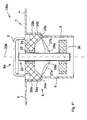
- the Fig. 1 shows a schematic representation of an inventive gutter system 100, which essentially comprises a gutter 1, a left base holder 2a, a right base holder 2b and a cover plate 3.
- the gutter 1 is located with an approximately horizontally shaped flange 4 on the pedestal holders 2 a and 2 b and further comprises a centrally disposed outlet connection 5.
- the gutter 1 further has a concave depression 6 with gutter bottoms 7a and 7b, which are arranged in a slope to the drain port 5.
- the cover plate 3 is U-shaped and can be turned on in this representation only suggestively recognizable bridge-like insert parts 8a-8d, so that in the mounted state on both sides of the cover 3 to the edges of the recess 6 each have a drain gap 9a and 9b remains open.
- the base holders 2a and 2b are adjustable in height, so basically the flange 4 can be tiled at will and the cover plate 3 is adjustable by means of the bridge-like insert parts 8a-8d on the tile surface, or the flange 4 is adjustable to the tile surface and the cover 3 then the height of the flange 4 is set.
- the Fig. 2 shows a further embodiment variant of an inventive gutter system 100a, which is the basic design variant of Fig. 1 only differs by a variably usable cover plate 3a.
- This Vario cover plate 3a is characterized by a cover plate top 10, which projects beyond a cover plate receptacle 11 on the sides to different degrees. As a result, the smallest tile laying work between the cover plate 3a and an end wall can be saved according to the invention.
- the left pedestal holder 2a is shown in more detail. It consists of a fixed angle holder 12a, an intermediate piece 13a, an adjustable angle holder 14a and four screw 15a-15d.
- the fixed angle holder 12a has bores 16 which are surrounded by a mounting band 17a on a lower adhesive surface 18a of a mounting band 17a and on a lateral adhesive surface 18b.
- the holes 16 on the one hand ensure improved adhesive properties of Adhesive surfaces 18 a and 18 b, on the other hand, but also the ability to apply the adhesive through the holes 16 at already positioned socket holder 2 a and 2 b.
- the fixed angle holder 12a has long holes 19a and 19b in which the screw joints 15c and 15d can slide to the intermediate piece 13a in a released state corresponding to a vertical axis 22.
- the long holes 19a and 19b and the corresponding slots in the intermediate piece 13a are equipped with a game, so that also results in a limited pivoting according to a pivoting direction 23.
- the fixed angle holder 12a further comprises a protective bow 20a and a mounting opening 21 through which either a laterally arranged siphon drain can be guided.
- the protective bow 20a prevents liquid concrete or mortar or glue from reaching the screw connections 15a-15d or the mounting opening 21.
- the same protection can be achieved by cladding the base holder 2a or 2b, for example, with a Styrofoam block and optionally cut at the desired setting height of support surfaces 25a and 25b for the underside of the flange 4.
- the intermediate piece 13a has the corresponding mounting opening 21 and also a corresponding Schutzbug 20b. Furthermore, the intermediate piece 13a has two elongated holes 19c and 19d, in which the screw connections 15a and 15b, if solved, allow a displacement of the adjustable angle holder 14a along an approximately horizontal axis 24.
- the adjustable angle holder 14a forms two support surfaces 25a and 25b, on which the gutter 3 from the Fig. 1 or the gutter from the Fig. 2 is hung up. These support surfaces 25a and 25b are glued to the sound decoupling with mounting bands 17c and 17d. The support surfaces 25a and 25b can optionally also have leveling screws.
- the Fig. 3b shows the right base holder 2b, mirrored to the base holder 2a from the Fig. 3a is configured, with corresponding individual components fixed angle bracket 12b, spacer 13b, adjustable angle bracket 14b, screw 15e-15h, and assembly lines 17e and 17f.
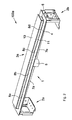
- the Fig. 4 shows a third embodiment variant of an inventive gutter system 100b, which is characterized by a cover 3b with a cover plate top 10a, which projects beyond the cover plate receptacle 11 on both sides only slightly. Furthermore, the shows Fig. 4 the left base holder 2a or the fixed angle holder 12a and the intermediate piece 13a and the right base holder 2b and the fixed angle holder 12b and the spacer 13b in the maximum extended state.
- FIG. 5 is the inventive gutter 1 from the FIGS. 1 . 2 and 4 shown alone.
- the depression 6 is made up of two oppositely approximately perpendicular support surfaces 26a and 26b, two adjoining oblique support surfaces 27a and 27b, and two discharge surfaces 28a and 28b which approximately horizontally close in a respective cross section.
- This outflow surface 28a and 28b form a mirror image of the outflow nozzle 5 a slope and at the same time run preferably pointed to the outflow nozzle 5.
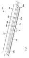
- the Fig. 6 shows a first embodiment variant of a further inventive inventive gutter 1a, which has an approximately perpendicular to a longitudinal side of the flange 4 aufbug 29.
- This Aufbug 29 offers, depending on the installation situation, on its back another adhesive surface 18c and on its front side an area to be tiled can.
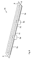
- a second embodiment variant of a further inventive drainage channel 1b is shown, which has a Abbug 30.
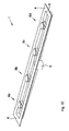
- FIG. 8 a further embodiment variant according to the invention of a gutter 1c with two outflow nozzles 5a and 5b is shown.
- Gutter bottoms 7c and 7d which taper to the center of the gutter 1c, show that from the center of the gutter 1c to the outlet nozzle 5a and 5b a gradient is formed in mirror image.
- FIG. 9 shows that in the FIGS. 1 . 2 and 4 merely indicated bridge-like insert part 8a, which consists essentially of a web 31 and a leveling screw with flat support head 32, wherein the latter is screwed in a thread 33 or preferably in a recessed threaded sleeve 33 and thus by rotations along a vertical axis 22a height-adjustable.
- the web 31 has two opposite approximately vertical support surfaces 34a and 34b, and two opposite inclined support surfaces 35a and 35b.
- Fig. 10 is shown, for example, as four bridge-like insert parts 8a-Bd are inserted into the gutter 1, so that a cover plate can be slipped over it.
- the Fig. 11 shows a further embodiment variant of an inventive gutter system 100c, which is characterized in that centrally above the drain port 5, a bridge-like insert part 8e is arranged with a correspondingly long thread as a leveling screw with flat support head 32. At the lower part of this thread a drain screen 36 is screwed. This results in a Height adjustability of the drain screen 36 along a vertical axis 22b. In this way, a non-contact, the drainage of the shower water does not impede positioning possibility of the drainage sieve 36, which simultaneously prevents the falling of valuables into the drain 5.
- the shows Fig. 11 how the bridge-like insert part 8e is supported on the gutter 1, namely by the vertical support surfaces 34a and 34b of the bridge-like insert part 8e are clamped between the vertical support surfaces 26a and 26b of the gutter 1 and by the inclined support surfaces 35a and 35b of the bridge-like insert part 8e itself only on the upper portion of the inclined support surfaces 27a and 27b of the gutter 1 support.
- the depression 6 formed by the lower region of the inclined support surfaces 27a and 27b and by the drainage surface 28a of the drainage channel 1 remains free for unhindered outflow of shower water, in the case of bridge-like insert parts 8a-8d without drainage screen 36 according to FIGS FIGS. 1 . 2 . 4 . 9 and 10 even more.
Landscapes
- Health & Medical Sciences (AREA)
- Life Sciences & Earth Sciences (AREA)
- Engineering & Computer Science (AREA)
- Hydrology & Water Resources (AREA)
- Public Health (AREA)
- Water Supply & Treatment (AREA)
- Sink And Installation For Waste Water (AREA)
- Sewage (AREA)
Applications Claiming Priority (1)
| Application Number | Priority Date | Filing Date | Title |
|---|---|---|---|
| DE202010002011U DE202010002011U1 (de) | 2010-02-05 | 2010-02-05 | Ablaufrinnen-System |
Publications (3)
| Publication Number | Publication Date |
|---|---|
| EP2354341A2 true EP2354341A2 (fr) | 2011-08-10 |
| EP2354341A3 EP2354341A3 (fr) | 2015-03-18 |
| EP2354341B1 EP2354341B1 (fr) | 2021-04-07 |
Family
ID=42538803
Family Applications (1)
| Application Number | Title | Priority Date | Filing Date |
|---|---|---|---|
| EP11000830.7A Active EP2354341B1 (fr) | 2010-02-05 | 2011-02-02 | Goulotte dotée d'un recouvrement réglable en hauteur |
Country Status (2)
| Country | Link |
|---|---|
| EP (1) | EP2354341B1 (fr) |
| DE (1) | DE202010002011U1 (fr) |
Cited By (5)
| Publication number | Priority date | Publication date | Assignee | Title |
|---|---|---|---|---|
| US20140201902A1 (en) * | 2012-03-15 | 2014-07-24 | Dlp Limited | Washing-area drainage trough |
| EP3056618A1 (fr) | 2015-02-10 | 2016-08-17 | SANIPAT GmbH | Socle de gouttiere reglable en hauteur pour recouvrir une gouttiere |
| US10513843B2 (en) * | 2015-07-31 | 2019-12-24 | Jesani Limited | Drainage |
| EP3978696A2 (fr) | 2020-10-01 | 2022-04-06 | ACO Ahlmann SE & Co. KG | Ensemble, aide à l'alignement, procédés et élément profilé |
| DE102020008099A1 (de) | 2020-10-01 | 2022-04-07 | Aco Ahlmann Se & Co. Kg | Profilelement |
Families Citing this family (7)
| Publication number | Priority date | Publication date | Assignee | Title |
|---|---|---|---|---|
| DE102010037138B3 (de) * | 2010-08-24 | 2012-02-02 | Viega Gmbh & Co. Kg | Ablaufrinne für bodengleiche Duschen |
| EP2806075B1 (fr) | 2013-05-21 | 2018-01-17 | SANIPAT GmbH | Recouvrement réglable pour rigole de douche |
| CH708080B1 (de) * | 2013-05-21 | 2017-08-15 | Sanipat Gmbh | Justierbare Duschrinnenabdeckung. |
| ES2651679T3 (es) * | 2013-06-26 | 2018-01-29 | Geberit International Ag | Entrada ajustable de un drenaje del suelo |
| DE102014111784C5 (de) * | 2013-09-16 | 2025-07-24 | Dallmer Gmbh & Co. Kg | Vorrichtung für einen beabstandet zu einer Wand im Boden eines Raumes angeordneten Bodenablauf |
| CH710589B1 (de) * | 2015-02-10 | 2019-02-28 | Sanipat Gmbh | Höhenjustierbarer Rinnensockel zum Einsetzen in eine Ablaufrinne. |
| EP4461893A1 (fr) * | 2023-04-28 | 2024-11-13 | TECE GmbH | Caniveau d'écoulement embouti |
Family Cites Families (4)
| Publication number | Priority date | Publication date | Assignee | Title |
|---|---|---|---|---|
| DE102004049944B4 (de) * | 2004-10-13 | 2015-04-02 | Dallmer Gmbh & Co. Kg | Ablaufvorrichtung für den Einbau in eine Bodenöffnung |
| CH698575B1 (de) * | 2006-07-05 | 2009-09-15 | Schaco Ag | Ablaufvorrichtung für eine Flüssigkeit. |
| DE202006014959U1 (de) * | 2006-09-27 | 2008-02-14 | Viega Gmbh & Co. Kg | Bodenablauf, insbesondere in Form einer Duschrinne |
| DE202009012621U1 (de) * | 2009-09-18 | 2009-12-10 | Aco Severin Ahlmann Gmbh & Co. Kg | Abdeckung für eine Ablaufrinne und Ablaufrinne mit solcher Abdeckung |
-
2010
- 2010-02-05 DE DE202010002011U patent/DE202010002011U1/de not_active Expired - Lifetime
-
2011
- 2011-02-02 EP EP11000830.7A patent/EP2354341B1/fr active Active
Non-Patent Citations (1)
| Title |
|---|
| None |
Cited By (7)
| Publication number | Priority date | Publication date | Assignee | Title |
|---|---|---|---|---|
| US20140201902A1 (en) * | 2012-03-15 | 2014-07-24 | Dlp Limited | Washing-area drainage trough |
| EP3056618A1 (fr) | 2015-02-10 | 2016-08-17 | SANIPAT GmbH | Socle de gouttiere reglable en hauteur pour recouvrir une gouttiere |
| US10513843B2 (en) * | 2015-07-31 | 2019-12-24 | Jesani Limited | Drainage |
| EP3978696A2 (fr) | 2020-10-01 | 2022-04-06 | ACO Ahlmann SE & Co. KG | Ensemble, aide à l'alignement, procédés et élément profilé |
| DE102020125692A1 (de) | 2020-10-01 | 2022-04-07 | Aco Ahlmann Se & Co. Kg | Set, Hilfsmittel zum Ausrichten, Verfahren und Profilelement |
| DE102020008099A1 (de) | 2020-10-01 | 2022-04-07 | Aco Ahlmann Se & Co. Kg | Profilelement |
| EP4177411A1 (fr) | 2020-10-01 | 2023-05-10 | ACO Ahlmann SE & Co. KG | Élément profilé |
Also Published As
| Publication number | Publication date |
|---|---|
| EP2354341A3 (fr) | 2015-03-18 |
| DE202010002011U1 (de) | 2010-08-05 |
| EP2354341B1 (fr) | 2021-04-07 |
Similar Documents
| Publication | Publication Date | Title |
|---|---|---|
| EP2354341A2 (fr) | Goulotte dotée d'un recouvrement réglable en hauteur | |
| EP2423394B1 (fr) | Rigole d'écoulement pour douches à même le sol | |
| EP2333174B1 (fr) | Système d'écoulement de douche | |
| EP1908887A1 (fr) | Siphon de sol en particulier sous forme d'une rainure de douche | |
| DE202007019020U1 (de) | Sanitäre Einrichtung mit einem Bodenablauf | |
| EP2756137B1 (fr) | Caniveau d'évacuation pour une douche ras du sol | |
| EP1378197B1 (fr) | Fondement pour un bac à douche | |
| DE102006026707A1 (de) | Duschwanne | |
| DE102012106924A1 (de) | Ablaufanordnung | |
| DE102006051130B4 (de) | Ablaufvorrichtung für die zumindest teilweise Einbringung in einen Boden eines Raumes | |
| DE202014010972U1 (de) | Vorrichtung für einen beabstandet zu einer Wand im Boden eines Raumes angeordneten Bodenablauf | |
| DE202011004001U1 (de) | Ablaufanordnung | |
| EP2995733B1 (fr) | Rigole d'ecoulement murale pour une douche | |
| EP3339522B1 (fr) | Système ou kit de fixation de caniveaux de douche | |
| DE102021118695A1 (de) | Bodenebene Duschtasse | |
| DE102011080284A1 (de) | Schattenfugenentwässerungssystem sowie Schlitzrinne und Ablauftopf für ein solches | |
| DE202006019811U1 (de) | Trägerelement für ein Duschbodenelement für bodengleiche Duschen | |
| DE102017112614B4 (de) | Überlaufrinnenanordnung für ein Schwimmbecken | |
| DE202010004650U1 (de) | Montagebefestigung für eine Ablaufrinne | |
| DE102017000145A1 (de) | Rinnen- Abwassersystem zum Ableiten von Flächenwasser auf Flächen (Balkone, Terrassen, Flachdächern ..) im Außenbereich. Mit dem System können Rinnen- Abwassersysteme in allen Abmessungen sehr einfach und schnell realisiert werden. | |
| EP1351360A1 (fr) | Boíte de jonction pour sol | |
| AT516332B1 (de) | Montagesatz zum Aufnehmen einer Scheibe und Installation mit einer montierten Scheibe | |
| DE20300839U1 (de) | Unterbau für ein Hock-Klosett | |
| DE202010012976U1 (de) | Sanitäreinrichtung und Untergestell-Montagesatz für die Montage einer Sanitäreinrichtung | |
| DE102017203122A1 (de) | Überlaufrinne für einen Türbereich eines Nassraums und Anordnung mit einer derartigen Überlaufrinne |
Legal Events
| Date | Code | Title | Description |
|---|---|---|---|
| PUAI | Public reference made under article 153(3) epc to a published international application that has entered the european phase |
Free format text: ORIGINAL CODE: 0009012 |
|
| AK | Designated contracting states |
Kind code of ref document: A2 Designated state(s): AL AT BE BG CH CY CZ DE DK EE ES FI FR GB GR HR HU IE IS IT LI LT LU LV MC MK MT NL NO PL PT RO RS SE SI SK SM TR |
|
| AX | Request for extension of the european patent |
Extension state: BA ME |
|
| RAP1 | Party data changed (applicant data changed or rights of an application transferred) |
Owner name: GASSMANN, URS |
|
| RIN1 | Information on inventor provided before grant (corrected) |
Inventor name: GASSMANN, URS |
|
| RIC1 | Information provided on ipc code assigned before grant |
Ipc: E03F 5/06 20060101AFI20141021BHEP |
|
| PUAL | Search report despatched |
Free format text: ORIGINAL CODE: 0009013 |
|
| AK | Designated contracting states |
Kind code of ref document: A3 Designated state(s): AL AT BE BG CH CY CZ DE DK EE ES FI FR GB GR HR HU IE IS IT LI LT LU LV MC MK MT NL NO PL PT RO RS SE SI SK SM TR |
|
| AX | Request for extension of the european patent |
Extension state: BA ME |
|
| RIC1 | Information provided on ipc code assigned before grant |
Ipc: E03F 5/06 20060101AFI20150206BHEP |
|
| 17P | Request for examination filed |
Effective date: 20150916 |
|
| RBV | Designated contracting states (corrected) |
Designated state(s): AL AT BE BG CH CY CZ DE DK EE ES FI FR GB GR HR HU IE IS IT LI LT LU LV MC MK MT NL NO PL PT RO RS SE SI SK SM TR |
|
| 17Q | First examination report despatched |
Effective date: 20160513 |
|
| STAA | Information on the status of an ep patent application or granted ep patent |
Free format text: STATUS: EXAMINATION IS IN PROGRESS |
|
| RAP1 | Party data changed (applicant data changed or rights of an application transferred) |
Owner name: SANIPAT GMBH |
|
| RIN1 | Information on inventor provided before grant (corrected) |
Inventor name: SANIPAT GMBH |
|
| RIN1 | Information on inventor provided before grant (corrected) |
Inventor name: GASSMANN, URS |
|
| RIN1 | Information on inventor provided before grant (corrected) |
Inventor name: GASSMANN, URS |
|
| GRAP | Despatch of communication of intention to grant a patent |
Free format text: ORIGINAL CODE: EPIDOSNIGR1 |
|
| STAA | Information on the status of an ep patent application or granted ep patent |
Free format text: STATUS: GRANT OF PATENT IS INTENDED |
|
| INTG | Intention to grant announced |
Effective date: 20200810 |
|
| RIN1 | Information on inventor provided before grant (corrected) |
Inventor name: GASSMANN, URS |
|
| GRAS | Grant fee paid |
Free format text: ORIGINAL CODE: EPIDOSNIGR3 |
|
| GRAA | (expected) grant |
Free format text: ORIGINAL CODE: 0009210 |
|
| STAA | Information on the status of an ep patent application or granted ep patent |
Free format text: STATUS: THE PATENT HAS BEEN GRANTED |
|
| AK | Designated contracting states |
Kind code of ref document: B1 Designated state(s): AL AT BE BG CH CY CZ DE DK EE ES FI FR GB GR HR HU IE IS IT LI LT LU LV MC MK MT NL NO PL PT RO RS SE SI SK SM TR |
|
| REG | Reference to a national code |
Ref country code: GB Ref legal event code: FG4D Free format text: NOT ENGLISH |
|
| REG | Reference to a national code |
Ref country code: AT Ref legal event code: REF Ref document number: 1379859 Country of ref document: AT Kind code of ref document: T Effective date: 20210415 Ref country code: CH Ref legal event code: EP |
|
| REG | Reference to a national code |
Ref country code: DE Ref legal event code: R096 Ref document number: 502011017095 Country of ref document: DE |
|
| REG | Reference to a national code |
Ref country code: IE Ref legal event code: FG4D Free format text: LANGUAGE OF EP DOCUMENT: GERMAN |
|
| REG | Reference to a national code |
Ref country code: LT Ref legal event code: MG9D |
|
| REG | Reference to a national code |
Ref country code: NL Ref legal event code: MP Effective date: 20210407 |
|
| RAP4 | Party data changed (patent owner data changed or rights of a patent transferred) |
Owner name: SANIPAT GMBH |
|
| PG25 | Lapsed in a contracting state [announced via postgrant information from national office to epo] |
Ref country code: BG Free format text: LAPSE BECAUSE OF FAILURE TO SUBMIT A TRANSLATION OF THE DESCRIPTION OR TO PAY THE FEE WITHIN THE PRESCRIBED TIME-LIMIT Effective date: 20210707 Ref country code: HR Free format text: LAPSE BECAUSE OF FAILURE TO SUBMIT A TRANSLATION OF THE DESCRIPTION OR TO PAY THE FEE WITHIN THE PRESCRIBED TIME-LIMIT Effective date: 20210407 Ref country code: FI Free format text: LAPSE BECAUSE OF FAILURE TO SUBMIT A TRANSLATION OF THE DESCRIPTION OR TO PAY THE FEE WITHIN THE PRESCRIBED TIME-LIMIT Effective date: 20210407 Ref country code: LT Free format text: LAPSE BECAUSE OF FAILURE TO SUBMIT A TRANSLATION OF THE DESCRIPTION OR TO PAY THE FEE WITHIN THE PRESCRIBED TIME-LIMIT Effective date: 20210407 Ref country code: NL Free format text: LAPSE BECAUSE OF FAILURE TO SUBMIT A TRANSLATION OF THE DESCRIPTION OR TO PAY THE FEE WITHIN THE PRESCRIBED TIME-LIMIT Effective date: 20210407 |
|
| PG25 | Lapsed in a contracting state [announced via postgrant information from national office to epo] |
Ref country code: NO Free format text: LAPSE BECAUSE OF FAILURE TO SUBMIT A TRANSLATION OF THE DESCRIPTION OR TO PAY THE FEE WITHIN THE PRESCRIBED TIME-LIMIT Effective date: 20210707 Ref country code: PT Free format text: LAPSE BECAUSE OF FAILURE TO SUBMIT A TRANSLATION OF THE DESCRIPTION OR TO PAY THE FEE WITHIN THE PRESCRIBED TIME-LIMIT Effective date: 20210809 Ref country code: PL Free format text: LAPSE BECAUSE OF FAILURE TO SUBMIT A TRANSLATION OF THE DESCRIPTION OR TO PAY THE FEE WITHIN THE PRESCRIBED TIME-LIMIT Effective date: 20210407 Ref country code: ES Free format text: LAPSE BECAUSE OF FAILURE TO SUBMIT A TRANSLATION OF THE DESCRIPTION OR TO PAY THE FEE WITHIN THE PRESCRIBED TIME-LIMIT Effective date: 20210407 Ref country code: RS Free format text: LAPSE BECAUSE OF FAILURE TO SUBMIT A TRANSLATION OF THE DESCRIPTION OR TO PAY THE FEE WITHIN THE PRESCRIBED TIME-LIMIT Effective date: 20210407 Ref country code: SE Free format text: LAPSE BECAUSE OF FAILURE TO SUBMIT A TRANSLATION OF THE DESCRIPTION OR TO PAY THE FEE WITHIN THE PRESCRIBED TIME-LIMIT Effective date: 20210407 Ref country code: LV Free format text: LAPSE BECAUSE OF FAILURE TO SUBMIT A TRANSLATION OF THE DESCRIPTION OR TO PAY THE FEE WITHIN THE PRESCRIBED TIME-LIMIT Effective date: 20210407 Ref country code: GR Free format text: LAPSE BECAUSE OF FAILURE TO SUBMIT A TRANSLATION OF THE DESCRIPTION OR TO PAY THE FEE WITHIN THE PRESCRIBED TIME-LIMIT Effective date: 20210708 Ref country code: IS Free format text: LAPSE BECAUSE OF FAILURE TO SUBMIT A TRANSLATION OF THE DESCRIPTION OR TO PAY THE FEE WITHIN THE PRESCRIBED TIME-LIMIT Effective date: 20210807 |
|
| REG | Reference to a national code |
Ref country code: DE Ref legal event code: R097 Ref document number: 502011017095 Country of ref document: DE |
|
| PG25 | Lapsed in a contracting state [announced via postgrant information from national office to epo] |
Ref country code: RO Free format text: LAPSE BECAUSE OF FAILURE TO SUBMIT A TRANSLATION OF THE DESCRIPTION OR TO PAY THE FEE WITHIN THE PRESCRIBED TIME-LIMIT Effective date: 20210407 Ref country code: SK Free format text: LAPSE BECAUSE OF FAILURE TO SUBMIT A TRANSLATION OF THE DESCRIPTION OR TO PAY THE FEE WITHIN THE PRESCRIBED TIME-LIMIT Effective date: 20210407 Ref country code: SM Free format text: LAPSE BECAUSE OF FAILURE TO SUBMIT A TRANSLATION OF THE DESCRIPTION OR TO PAY THE FEE WITHIN THE PRESCRIBED TIME-LIMIT Effective date: 20210407 Ref country code: EE Free format text: LAPSE BECAUSE OF FAILURE TO SUBMIT A TRANSLATION OF THE DESCRIPTION OR TO PAY THE FEE WITHIN THE PRESCRIBED TIME-LIMIT Effective date: 20210407 Ref country code: CZ Free format text: LAPSE BECAUSE OF FAILURE TO SUBMIT A TRANSLATION OF THE DESCRIPTION OR TO PAY THE FEE WITHIN THE PRESCRIBED TIME-LIMIT Effective date: 20210407 Ref country code: DK Free format text: LAPSE BECAUSE OF FAILURE TO SUBMIT A TRANSLATION OF THE DESCRIPTION OR TO PAY THE FEE WITHIN THE PRESCRIBED TIME-LIMIT Effective date: 20210407 |
|
| PLBE | No opposition filed within time limit |
Free format text: ORIGINAL CODE: 0009261 |
|
| STAA | Information on the status of an ep patent application or granted ep patent |
Free format text: STATUS: NO OPPOSITION FILED WITHIN TIME LIMIT |
|
| 26N | No opposition filed |
Effective date: 20220110 |
|
| PGFP | Annual fee paid to national office [announced via postgrant information from national office to epo] |
Ref country code: AT Payment date: 20220215 Year of fee payment: 12 |
|
| PG25 | Lapsed in a contracting state [announced via postgrant information from national office to epo] |
Ref country code: IS Free format text: LAPSE BECAUSE OF FAILURE TO SUBMIT A TRANSLATION OF THE DESCRIPTION OR TO PAY THE FEE WITHIN THE PRESCRIBED TIME-LIMIT Effective date: 20210807 Ref country code: AL Free format text: LAPSE BECAUSE OF FAILURE TO SUBMIT A TRANSLATION OF THE DESCRIPTION OR TO PAY THE FEE WITHIN THE PRESCRIBED TIME-LIMIT Effective date: 20210407 |
|
| PG25 | Lapsed in a contracting state [announced via postgrant information from national office to epo] |
Ref country code: IT Free format text: LAPSE BECAUSE OF FAILURE TO SUBMIT A TRANSLATION OF THE DESCRIPTION OR TO PAY THE FEE WITHIN THE PRESCRIBED TIME-LIMIT Effective date: 20210407 |
|
| PG25 | Lapsed in a contracting state [announced via postgrant information from national office to epo] |
Ref country code: MC Free format text: LAPSE BECAUSE OF FAILURE TO SUBMIT A TRANSLATION OF THE DESCRIPTION OR TO PAY THE FEE WITHIN THE PRESCRIBED TIME-LIMIT Effective date: 20210407 |
|
| REG | Reference to a national code |
Ref country code: BE Ref legal event code: MM Effective date: 20220228 |
|
| GBPC | Gb: european patent ceased through non-payment of renewal fee |
Effective date: 20220202 |
|
| PG25 | Lapsed in a contracting state [announced via postgrant information from national office to epo] |
Ref country code: LU Free format text: LAPSE BECAUSE OF NON-PAYMENT OF DUE FEES Effective date: 20220202 |
|
| PG25 | Lapsed in a contracting state [announced via postgrant information from national office to epo] |
Ref country code: FR Free format text: LAPSE BECAUSE OF NON-PAYMENT OF DUE FEES Effective date: 20220228 |
|
| PG25 | Lapsed in a contracting state [announced via postgrant information from national office to epo] |
Ref country code: IE Free format text: LAPSE BECAUSE OF NON-PAYMENT OF DUE FEES Effective date: 20220202 Ref country code: GB Free format text: LAPSE BECAUSE OF NON-PAYMENT OF DUE FEES Effective date: 20220202 |
|
| PG25 | Lapsed in a contracting state [announced via postgrant information from national office to epo] |
Ref country code: BE Free format text: LAPSE BECAUSE OF NON-PAYMENT OF DUE FEES Effective date: 20220228 |
|
| PGFP | Annual fee paid to national office [announced via postgrant information from national office to epo] |
Ref country code: CH Payment date: 20230307 Year of fee payment: 13 |
|
| PGFP | Annual fee paid to national office [announced via postgrant information from national office to epo] |
Ref country code: DE Payment date: 20230216 Year of fee payment: 13 |
|
| REG | Reference to a national code |
Ref country code: AT Ref legal event code: MM01 Ref document number: 1379859 Country of ref document: AT Kind code of ref document: T Effective date: 20230202 |
|
| PG25 | Lapsed in a contracting state [announced via postgrant information from national office to epo] |
Ref country code: AT Free format text: LAPSE BECAUSE OF NON-PAYMENT OF DUE FEES Effective date: 20230202 |
|
| PG25 | Lapsed in a contracting state [announced via postgrant information from national office to epo] |
Ref country code: HU Free format text: LAPSE BECAUSE OF FAILURE TO SUBMIT A TRANSLATION OF THE DESCRIPTION OR TO PAY THE FEE WITHIN THE PRESCRIBED TIME-LIMIT; INVALID AB INITIO Effective date: 20110202 |
|
| PG25 | Lapsed in a contracting state [announced via postgrant information from national office to epo] |
Ref country code: MK Free format text: LAPSE BECAUSE OF FAILURE TO SUBMIT A TRANSLATION OF THE DESCRIPTION OR TO PAY THE FEE WITHIN THE PRESCRIBED TIME-LIMIT Effective date: 20210407 Ref country code: CY Free format text: LAPSE BECAUSE OF FAILURE TO SUBMIT A TRANSLATION OF THE DESCRIPTION OR TO PAY THE FEE WITHIN THE PRESCRIBED TIME-LIMIT Effective date: 20210407 |
|
| PG25 | Lapsed in a contracting state [announced via postgrant information from national office to epo] |
Ref country code: TR Free format text: LAPSE BECAUSE OF FAILURE TO SUBMIT A TRANSLATION OF THE DESCRIPTION OR TO PAY THE FEE WITHIN THE PRESCRIBED TIME-LIMIT Effective date: 20210407 |
|
| REG | Reference to a national code |
Ref country code: DE Ref legal event code: R119 Ref document number: 502011017095 Country of ref document: DE |
|
| PG25 | Lapsed in a contracting state [announced via postgrant information from national office to epo] |
Ref country code: MT Free format text: LAPSE BECAUSE OF FAILURE TO SUBMIT A TRANSLATION OF THE DESCRIPTION OR TO PAY THE FEE WITHIN THE PRESCRIBED TIME-LIMIT Effective date: 20210407 |
|
| REG | Reference to a national code |
Ref country code: CH Ref legal event code: PL |
|
| PG25 | Lapsed in a contracting state [announced via postgrant information from national office to epo] |
Ref country code: CH Free format text: LAPSE BECAUSE OF NON-PAYMENT OF DUE FEES Effective date: 20240229 |
|
| PG25 | Lapsed in a contracting state [announced via postgrant information from national office to epo] |
Ref country code: CH Free format text: LAPSE BECAUSE OF NON-PAYMENT OF DUE FEES Effective date: 20240229 |
|
| PG25 | Lapsed in a contracting state [announced via postgrant information from national office to epo] |
Ref country code: DE Free format text: LAPSE BECAUSE OF NON-PAYMENT OF DUE FEES Effective date: 20240903 |
|
| PG25 | Lapsed in a contracting state [announced via postgrant information from national office to epo] |
Ref country code: DE Free format text: LAPSE BECAUSE OF NON-PAYMENT OF DUE FEES Effective date: 20240903 |