EP1844708A2 - Vorrichtung zur Steuerung und Detektion eines elektrischen Feldes - Google Patents
Vorrichtung zur Steuerung und Detektion eines elektrischen Feldes Download PDFInfo
- Publication number
- EP1844708A2 EP1844708A2 EP07007097A EP07007097A EP1844708A2 EP 1844708 A2 EP1844708 A2 EP 1844708A2 EP 07007097 A EP07007097 A EP 07007097A EP 07007097 A EP07007097 A EP 07007097A EP 1844708 A2 EP1844708 A2 EP 1844708A2
- Authority
- EP
- European Patent Office
- Prior art keywords
- electrode
- signal
- electric field
- frame
- electric
- Prior art date
- Legal status (The legal status is an assumption and is not a legal conclusion. Google has not performed a legal analysis and makes no representation as to the accuracy of the status listed.)
- Granted
Links
Images








Classifications
-
- A—HUMAN NECESSITIES
- A61—MEDICAL OR VETERINARY SCIENCE; HYGIENE
- A61B—DIAGNOSIS; SURGERY; IDENTIFICATION
- A61B5/00—Measuring for diagnostic purposes; Identification of persons
- A61B5/05—Detecting, measuring or recording for diagnosis by means of electric currents or magnetic fields; Measuring using microwaves or radio waves
- A61B5/053—Measuring electrical impedance or conductance of a portion of the body
- A61B5/0537—Measuring body composition by impedance, e.g. tissue hydration or fat content
-
- H—ELECTRICITY
- H10—SEMICONDUCTOR DEVICES; ELECTRIC SOLID-STATE DEVICES NOT OTHERWISE PROVIDED FOR
- H10D—INORGANIC ELECTRIC SEMICONDUCTOR DEVICES
- H10D12/00—Bipolar devices controlled by the field effect, e.g. insulated-gate bipolar transistors [IGBT]
-
- A—HUMAN NECESSITIES
- A61—MEDICAL OR VETERINARY SCIENCE; HYGIENE
- A61B—DIAGNOSIS; SURGERY; IDENTIFICATION
- A61B5/00—Measuring for diagnostic purposes; Identification of persons
- A61B5/05—Detecting, measuring or recording for diagnosis by means of electric currents or magnetic fields; Measuring using microwaves or radio waves
-
- A—HUMAN NECESSITIES
- A61—MEDICAL OR VETERINARY SCIENCE; HYGIENE
- A61B—DIAGNOSIS; SURGERY; IDENTIFICATION
- A61B5/00—Measuring for diagnostic purposes; Identification of persons
- A61B5/41—Detecting, measuring or recording for evaluating the immune or lymphatic systems
- A61B5/414—Evaluating particular organs or parts of the immune or lymphatic systems
- A61B5/417—Evaluating particular organs or parts of the immune or lymphatic systems the bone marrow
-
- A—HUMAN NECESSITIES
- A61—MEDICAL OR VETERINARY SCIENCE; HYGIENE
- A61B—DIAGNOSIS; SURGERY; IDENTIFICATION
- A61B5/00—Measuring for diagnostic purposes; Identification of persons
- A61B5/48—Other medical applications
- A61B5/4887—Locating particular structures in or on the body
- A61B5/489—Blood vessels
-
- A—HUMAN NECESSITIES
- A61—MEDICAL OR VETERINARY SCIENCE; HYGIENE
- A61B—DIAGNOSIS; SURGERY; IDENTIFICATION
- A61B2562/00—Details of sensors; Constructional details of sensor housings or probes; Accessories for sensors
- A61B2562/18—Shielding or protection of sensors from environmental influences, e.g. protection from mechanical damage
- A61B2562/182—Electrical shielding, e.g. using a Faraday cage
-
- A—HUMAN NECESSITIES
- A61—MEDICAL OR VETERINARY SCIENCE; HYGIENE
- A61B—DIAGNOSIS; SURGERY; IDENTIFICATION
- A61B5/00—Measuring for diagnostic purposes; Identification of persons
- A61B5/02—Detecting, measuring or recording for evaluating the cardiovascular system, e.g. pulse, heart rate, blood pressure or blood flow
- A61B5/02028—Determining haemodynamic parameters not otherwise provided for, e.g. cardiac contractility or left ventricular ejection fraction
- A61B5/02035—Determining blood viscosity
-
- A—HUMAN NECESSITIES
- A61—MEDICAL OR VETERINARY SCIENCE; HYGIENE
- A61B—DIAGNOSIS; SURGERY; IDENTIFICATION
- A61B5/00—Measuring for diagnostic purposes; Identification of persons
- A61B5/08—Measuring devices for evaluating the respiratory organs
- A61B5/085—Measuring impedance of respiratory organs or lung elasticity
- A61B5/086—Measuring impedance of respiratory organs or lung elasticity by impedance pneumography
-
- A—HUMAN NECESSITIES
- A61—MEDICAL OR VETERINARY SCIENCE; HYGIENE
- A61B—DIAGNOSIS; SURGERY; IDENTIFICATION
- A61B5/00—Measuring for diagnostic purposes; Identification of persons
- A61B5/41—Detecting, measuring or recording for evaluating the immune or lymphatic systems
- A61B5/414—Evaluating particular organs or parts of the immune or lymphatic systems
- A61B5/418—Evaluating particular organs or parts of the immune or lymphatic systems lymph vessels, ducts or nodes
Definitions
- the present invention contains subject matter related to Japanese Patent Application JP 2006-112270 filed in the Japanese Patent Office on April 14, 2006, the entire contents of which being incorporated herein by reference.
- the present invention relates to an electric field control device and a detection device which may be suitably applied to the case of detecting the state of a blood vessel non-invasively.
- this detection device detects the impedance of a living organism, which is placed in the quasi-electrostatic fields generated by a plurality of electrodes, from the electrodes respectively, and detects whether or not blood exists in the inside of the living organism based on the detection result.
- this detection device there are arranged conductive members for dividing off the electrodes respectively, which conductive members are electrically separated from the plural electrodes, and the conductive members are so configured as to narrow down the quasi-electrostatic fields generated by the respective electrodes by means of dividing-off surfaces thereof.
- the conductive member is merely arranged around the circumference of the electrode, the potential is changed depending on the quasi-electrostatic field transmitted by the electrode. Accordingly, inthisdetectiondevice, since the quasi-electrostatic field is transmitted to the outside of the conductive member, the transmission efficiency of the quasi-electrostatic field is deteriorated.
- an electric field control device that applies electric fields to an electric field application subject, including: a first electrode and a second electrode that generate the electric fields; a frame that is arranged around the first electrode and second electrode, and is connected to the first electrode and second electrode; an opening that is formed at one end of the frame; and an output means for outputting a first signal to the first electrode, and outputting a second signal to the second electrode; wherein, when the electric fields are generated from the first electrode and second electrode, the output means outputs the second signal to the second electrode so that the potential of the frame is not changed temporally and made constant.
- the second electrode comes to be provided with the function of suppressing the oscillation of the frame due to the electric field generated by the first electrode to which the first signal is output, irrespective of the fact that whether or not the frame is grounded, the electric field generated by the first electrode to which the first signal is output and the electric field generated by the second electrode to which the second signal is output negate each other. Accordingly, the electric fields do not leak to the outside of the frame due to the oscillation thereof, and the electric fields are applied to the opening direction of the frame. As a result, in the electric field control device, the influence from the outside of the frame with respect to the electric fields can be reduced, and the electric fields can be narrowed down to the opening direction.
- a detection device that detects a predetermined detection subject in a living organism, including: a first electrode and a second electrode; a frame that is arranged around the first electrode and second electrode, and is connected to the first electrode and second electrode; an opening that is formed at one end of the frame; an output means for outputting a first signal and a second signal to the corresponding first electrode and second electrode by setting frequencies thereof so that, in the electric fields formed through the opening by the first electrode and second electrode, the intensity of the quasi-electrostatic fields is superior as compared with that of the induction fields at a predetermined distance; an impedance detection means for detecting the impedance of the living organism placed in the electric fields from the first electrode and second electrode; and a colloid detection means for detecting whether or not a colloid exists in the inside of the living organism according to the difference of the respective detected impedances; wherein, when the electric fields are generated from the first electrode and second electrode, the output means outputs the second signal to the
- the second electrode comes to be provided with the function of suppressing the oscillation of the frame due to the electric field generated by the first,electrode to which the first signal is output, irrespective of the fact that whether or not the frame is grounded, the electric field generated by the first electrode to which the first signal is output and the electric field generated by the second electrode to which the second signal is output negate each other. Accordingly, the electric fields do not leak to the outside of the frame due to the oscillation thereof, and the electric fields are applied to the opening direction of the frame.
- the influence from the outside of the frame with respect to the electric fields can be reduced, and the electric fields can be narrowed down to the opening direction, which makes it possible to accurately detect whether or not a colloid exists in the inside of the living organism according to the difference of the impedances.
- the influence from the outside of the frame with respect to the electric fields canbe reduced, and the electric fields canbe narrowed down to the opening direction, which makes it possible to provide an electric field control device that can generate the electric field more effectively and a detection device that can improve detection accuracy.
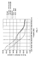
- FIG. 1 shows a graphical representation indicative of the relationship between the frequency and relative dielectric constant of respective tissues in the inside of a human organism
- FIG. 2 shows a graphical representation indicative of the relationship between the frequency and electrical conductivity.
- Those frequency, relative dielectric constant, and electrical conductivity are represented by exponents.
- FIG. 1 and FIG. 2 even if the relative dielectric constant and electrical conductivity of the respective tissues are unique, being congested in high frequency bands, it is inconvenient to detect a specific tissue using the high frequency bands.
- the difference between the relative dielectric constants and electrical conductivities of the respective tissues are made large in low frequency bands, it is convenient to detect a specific tissue using the low frequency bands.
- values of blood are clearly different from those of other tissues from approximately 1 MHz to 10 MHz, the blood is convenient as a subject to be detected.
- the state of a blood vessel is detected non-invasively from above the skin based on the change in impedance in the biomedical tissues.
- a signal in a frequency band in which the electrical characteristics of the various biomedical tissues in a living organism are scattered are applied to a plurality of electrodes, and the impedances of the living organism placed in the quasi-electrostatic fields transmitted by the plural respective electrodes are detected from the electrodes respectively.
- the impedance becomes small when the electrode position comes close to a blood vessel (blood), it is possible to detect under which electrode the blood vessel exists based on the difference in impedances detected by the respective electrodes.
- the impedance becomes small when the electrode position comes close to a blood vessel (blood)
- a blood vessel blood
- the electric field there is generated a composite electric field composed of a radiation field that is inversely proportional to the distance from the electric field source linearly, an induction field that is inversely proportional to the square of the distance from the electric field source, and a quasi-electrostatic field that is inversely proportional to the cube of the distance from the electric field source.
- the quasi-electrostatic field has a high resolution with respect to the distance, of the electric fields generated from the electric field source, when the intensity of the induction field and the intensity of the radiation field are weakened, it becomes possible to measure the impedances of the biomedical tissues with high accuracy.
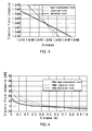
- FIG. 3 shows a graphical representation indicative of the relationship between the relative intensities of the respective radiation field, induction field, quasi-electrostatic field and the distance.
- the relationship between the relative intensities of the respective electric fields and the distance in 1 MHz is represented by exponents.
- intensity boundary point a distance at which the relative intensities of the respective radiation field, induction field, and quasi-electrostatic field are equal to each other.
- the radiation field is superior (the intensity of the radiation field is larger than those of the induction field and quasi-electrostatic field) in a space which is farther than the intensity boundary point
- the quasi-electrostatic field is superior (the intensity of the quasi-electrostatic field is larger than those of the radiation field and induction field) in a space which is closer than the intensity boundary point.
- the intensity boundary point can be represented by the following mathematical expression, where the distance is "r" m and the wave number is "k" 1/m.
- Formula 1 r 1 k
- the wave number "k” in the mathematical expression (1) can be represented by the following mathematical expression, where the transmission speed in medium in the electric field is "v" m/s and the frequency is "f" Hz.
- Formula 2 k 2 ⁇ ⁇ f v
- Formula 3 v c ⁇ ⁇
- the intensity boundary point can be represented by the following mathematical expression that is obtained by inputting the mathematical expressions (2) and (3) into the mathematical expression (1) and arranging the resultant mathematical expression.
- Formula 4 r c 2 ⁇ ⁇ f ⁇ ⁇ ⁇
- the frequency is closely related, and the lower the frequency is, the broader the quasi-electrostatic field superiority space becomes. That is, the lower the frequency is, the longer the distance to the intensity boundary point shown in FIG. 3 becomes, more specifically, the intensity boundary point shifts to the right.
- the higher the frequency is, the narrower the quasi-electrostatic field superiority space becomes. That is, the higher the frequency is, the shorter the distance to the intensity boundary point shown in FIG. 3 becomes, more specifically, the intensity boundary point shifts to the left.
- FIG. 4 shows a graphical representation indicative of the relationship between the relative intensities of the respective radiation field, induction field, quasi-electrostatic field and the distance in case 10 MHz is selected.
- the intensity of the quasi-electrostatic field at 0.01 m point from the electric field source becomes large by 18.2 dB as compared with that of the induction field. Accordingly, it can be considered that the quasi-electrostatic field in this case is not influenced by the induction field and radiation field.
- a signal of a low frequency band is applied to electrodes arranged at the surface of a living organism, and a specific tissue (especially, a blood vessel) can be detected based on the impedances of the living organism placed in the quasi-electrostatic fields transmitted by the electrodes.
- the quasi-electrostatic field spreads to the surrounding area from the electrode, the mutual interaction result of the quasi-electrostatic field that is not emitted on the living organism and fluctuating elements other than the living organism influences the impedance of the living organism placed in the quasi-electrostatic field, which may not attain the purpose of improving the detection accuracy.
- a method of arranging a frame made of conductive material to enclose the electrode in all directions excluding the irradiation direction (or direction facing the surface of the living organism), and grounding the conductive frame.
- a cylindrical electrode with the radius 0. 5 mm is employed, and, as the conductive frame enclosing the electrode, a cylindrical conductive frame in the form of a concavity in its cross-section with the inside diameter 1.0 mm and outside diameter 1.5 mm is employed.
- the conductive frame is not grounded, that is electrically floating, and a signal of 10 MHz in frequency is applied to the electrode.
- the electrical characteristics in the living organism are set equal with those of the muscle (relative dielectric constant 170 and electrical conductivity 0.6 S/m).
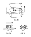
- this third simulation model as shown in FIGS. 7A to 7C, there are employed a disciform electrode Ea, a ringlike electrode Eb that has its center made to accord with the electrode Ea and symmetrically encloses the electrode Ea, and a conductive frame FM that symmetrically encloses the entire circumference of the electrodes Ea and Eb with the electrode Ea being the center excluding an opening OP being the electric field irradiation part.
- the electrodes Ea and Eb are arranged on the same plane, and are so placed as to be in contact with the surface of the opening OP of the conductive frame FM.
- the signal to be applied to the electrode Ea has its frequency set to 10 MHz and has its amplitude set to 1 V, while the signal to be applied to the electrode Eb has its frequency set to 10 MHz whose phase is shifted by 180 °as compared with that of the signal to be applied to the electrode Ea and has its amplitude set variable arbitrarily. Then, the electric field intensity between the conductive frame FM and a ground plate GND that corresponds to the potential of the ground is detected. In case the electric field intensity is sufficiently small, it is considered that there is no potential change in the conductive frame FM and the potential is constant.
- FIG. 8 shows a table indicative of the result of the third simulation.
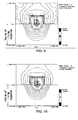
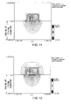
- FIG. 9 to FIG. 12 shows electric field distribution patterns which are parts of the simulation result. The electric field distribution patterns shown in FIG. 9 to FIG. 12 are appended as reference FIG. 3 to reference FIG. 6.
- the amplitude ratio of the signals to be applied to the electrodes Ea and Eb is changed depending on the electrode shape, electrode arrangement state, and conductive frame shape. Accordingly, actually, in the state in which the paired electrodes and conductive frame are built up, the amplitude ratio of the signals to be applied to the paired electrodes is determined such that the electric field intensity is made small at potions of the conductive frame where the electrodes are in closest proximity to the inner wall thereof.
- EEM-FDM multipurpose electromagnetic wave analysis software
- Information and Mathematical Science Laboratory Inc. This is a software that discretizes the Maxwell equations with the difference method with respect to a specified frequency, and calculates the electric field, magnetic field, and impedance between feeding electrodes in a space.
- FIG. 13 shows a block diagram indicative of the configuration of an embodiment of a detection device 1 that detects a specific tissue using the impedances of the biomedical tissues.
- the detection device 1 includes an impedance detection unit 2 and a blood vessel detection unit 3.
- the impedance detection unit 2 includes a plurality of electrode units UT1 to UTn which are to abut on a detection subject of a living organism.
- Each of these electrode units UT1 to UTn includes the paired electrodes Ea, Eb, and conductive frame FM shown in FIGS. 7A to 7C.
- each of these electrode units UT1 to UTn includes the disciform electrode Ea, the ringlike electrode Eb that has its center made to accord with the electrode Ea and symmetrically encloses the electrode Ea, and the conductive frame FM that symmetrically encloses the entire circumference of the electrodes Ea and Eb with the electrode Ea being the center excluding the opening OP being the electric field irradiation part.
- the electrodes Ea and Eb are arranged on the same plane, and are so placed as to be in contact with the surface of the opening OP of the conductive frame FM.
- the sizes of the electrodes Ea, Eb, and conductive frame FM of the electrode units UT are not restricted to those described using FIGS. 7A to 7C, and are arbitrarily selected.
- these electrode units UT1 to UTn are arranged in a lattice-shaped pattern with the surfaces of the openings OP of the conductive frames FM placed on the same plane, and are unitedly formed with the neighboring conductive frames FM coupled with each other, which conductive frames FM are grounded.
- FIG. 13 for the sake of convenience, the state in which the electrode units UT1 to UTn are arranged in a line is shown.
- the material of the conductive frame FM As the material of the conductive frame FM, a material having the flexibility is selected. Accordingly, even if these electrode units UT1 to UTn are unitedly formed, the electrodes Ea and Eb thereof which are so placed as to be in contact with the surfaces of the openings OP of the respective conductive frames FM can be attached firmly to the uneven surface of the living organism.
- a signal that has its frequency set to, for example, 10 MHz is sent from a signal output control unit 20.
- This signal is selected with an index concerning under which low frequency band or lower frequency bands the electrical conductivity and relative dielectric constant of a biomedical tissue to be detected can be clearly differentiated from those of other tissues, or approximately which depth a biomedical tissue to be detected exists from the surface of the living organism.
- the quasi-electrostatic fields generated from the electrodes Ea, Eb come to be emitted on the living organism in the superior state (the intensity of the quasi-electrostatic fields are larger than those of the radiation fields and induction fields) in a space in close proximity to the electrodes (space to the distance corresponding to the selected frequency).
- measurement results SA1 to SAn by amperemeters CM1 to CMn which are arranged between a signal generation source 25 and the respective electrode units UT1 to UTn are supplied through corresponding switches SW1 to SWn, and a measurement result SV by a voltmeter VM corresponding to the signal generation source 25 is also supplied.
- the impedance calculation unit 21 calculates impedance values corresponding to the respective electrode units UT1 to UTn, using the ratio of the measurement result SA1 by the amperemeter CM1 and the measurement result SV by the voltmeter VM, ratio of the measurement result SA2 by the amperemeter CM2 and the measurement result SV by the voltmeter VM, ⁇ , and ratio of the measurement result SAn by the amperemeter CMn and the measurement result SV by the voltmeter VM.
- calculated impedance values are represented in the form of complex numbers.
- the impedance calculation unit 21 outputs thus obtained impedance values corresponding to the respective electrode units UT1 to UTn to the blood vessel detection unit 3 as data (referred to as impedance data, hereinafter) IP1 to IPn.
- the impedance detection unit 2 can detect the impedances of the biomedical tissues.
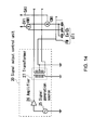
- FIG. 14 shows a schematic view indicative of the configuration of the signal output control unit 20 of the impedance detection unit 2.
- the signal output control unit 20 includes the signal generation source 25, an amplifier 26, and a transformer 27, and a sinusoidal signal of 10 MHz transmitted from the signal generation source 25 is amplified by the amplifier 26, and thus amplified signal is output to the primary coil of the transformer 27.
- One end of the secondary coil of the transformer 27 is connected to the electrodes Ea of the respective electrode units UT (UT1 to UTn), while the other end of the secondary coil is connected to the electrodes Eb of the respective electrode units UT.
- the secondary coil of the transformer 27 has arranged thereon a plurality of taps, not shown, at predetermined winding intervals, and one tap thereof is connected to the ground for the conductive frames FM of the respective electrode units UT.
- this one tap sets the electric field intensity minimum at potions of the conductive frames FM of the electrode units UT where the electrodes Eb are in closest proximity to the inner wall thereof.
- the signal that is transformed by the transformer 27 is output as a signal that has its phase changed by 180 ° and is of a predetermined amplitude ratio.
- This amplitude ratio is arbitrarily changed depending on the configuration of the electrode units UT such as the relationship among the clearance between the electrodes Ea and the electrodes Eb and the clearance between the electrodes Eb and the conductive frames FM, and the shape of the electrodes Ea, Eb, and conductive frames FM.
- the quasi-electrostatic fields generated from the core electrodes Ea and the quasi-electrostatic fields generated from the electrodes Eb enclosing the core electrodes Ea negate each other before getting to the conductive frames FM of the electrode units UT, suppressing the fluctuation of the potential of the conductive frames FM.
- the quasi-electrostatic fields generated from the respective electrode units UT are irradiated to the living organism in the limited downward direction under the paired electrodes Ea and Eb.
- the signal output control unit 20 is so configured as to emit the quasi-electrostatic fields in the limited downward direction under the paired electrodes Ea and Eb of the electrode units UT.
- the blood vessel detection unit 3 includes a Central Processing Unit (CPU) 31, and further a Read Only Memory (ROM) 32 that stores predetermined programs, a Random Access Memory (RAM) 33 that works as a work memory for the CPU 31, a cache memory 34, and an Electrically Erasable Programmable ROM (EEPROM) 35, which are mutually connected to the CPU 31.
- CPU Central Processing Unit
- ROM Read Only Memory
- RAM Random Access Memory
- EEPROM Electrically Erasable Programmable ROM
- the CPU 31 carries out the blood vessel detection processing by arbitrarily controlling the cache memory 34, EEPROM 35, and impedance detection unit 2 shown in FIG. 13 in accordance with the programs stored in the ROM 32.
- the CPU 31 controls to switch the electrode units UT to which the signal output from the signal generation source 25 shown in FIG. 14 is sent so that the signal can be sequentially supplied to the respective electrode units UT.
- the CPU 31 can prevent the impedance detection unit 2 from detecting the impedances due to the mutual interaction among quasi-electrostatic fields generated from the neighboring electrodes beforehand.
- the CPU 31 stores the impedance data IP1 to IPn sequentially supplied from the impedance calculation unit 21 in the cache memory 34, and processes thus stored impedance data IP1 to IPn with electrodes (referred to as unit electrode group, hereinafter) SU of m-row and n-column being a unit, as shown in FIG. 16.
- electrodes referred to as unit electrode group, hereinafter
- values of the impedance data IP1 to IPn are replaced to a matrix corresponding to the arrangement of the electrodes, and, based on the matrix, the minimum impedance is detected for each unit electrode group SU.
- the minimum impedance position (ko, jo) represents the center of cross-section surface of a blood vessel in the blood flow direction.
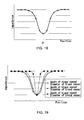
- the CPU 31 recognizes the change in impedance around the minimum impedance position (ko, jo), and reads out dictionary data DC that has been recorded in the EEPROM 35 in advance.
- this dictionary data DC is data that represents the change in impedance around the reference position (k, j), and the depth of blood vessel and diameter of blood vessel in the living organism corresponding to the change.
- FIG. 18 and FIG. 19 for the sake of convenience, the degree of change in impedance around the "j" direction from the reference position (k, j) and the distance from the reference position (k, j) are shown.
- the CPU 31 determines the depth of blood vessel and diameter of blood vessel corresponding to the change in impedance which is recognized at this time.
- the depth of blood vessel and diameter of blood vessel can be determined.
- the detection device 1 since the impedance can be detected for the respective electrode units UT1 to UTn through the quasi-electrostatic fields of a frequency band in which the electrical characteristics of the various biomedical tissues are scattered, even if the electrical characteristics of the various biomedical tissues in the living organism are reflected on the impedance, the case in which a blood vessel exists in the quasi-electrostatic fields and the case in which no blood vessel exists therein can be accurately differentiated from the difference of the respective impedances detected from the respective electrode units UT1 to UTn.
- the frequency band in which the electrical characteristics of the various biomedical tissues are scattered is a low frequency band
- the intensity of the quasi-electrostatic field that is transmitted according to the signal of the low frequency band is superior as compared with those of the radiation field and induction field
- the influence of the radiation field and induction field is not reflected on the impedance detected by the respective electrode units UT1 to UTn through the quasi-electrostatic fields, which can differentiate the existence or nonexistence of blood more accurately.
- the impedance of the living organism placed in the quasi-electrostatic fields can be detected without being influenced by the materials lying between the surface of the living organism and the electrodes.
- the detection device 1 since the width of blood vessel (diameter of blood vessel) and depth of blood vessel are determined with the distance between the electrodes and the degree of change in impedance detected from the electrodes being the reference, much information concerning blood can be non-invasively and accurately obtained. Accordingly, when the diameter of blood vessel and depth of blood vessel are generated as biometric identification data, it becomes possible to prevent lowering of accuracy in discriminating whether or not an examined person is the identical person (False Rejection Rate (FRR), False Acceptance Rate (FAR)) based on the biometric identification data.
- FRR False Acceptance Rate
- FAR False Acceptance Rate
- the core electrode Ea and the electrode Eb enclosing the core electrode Ea are enclosed by the conductive frame FM excluding the electric field irradiation direction (refer to FIG. 7B), and the first signal is output to the electrode Ea.
- the second signal that has its waveform selected (refer to FIG. 8) on the basis of the first signal is output so that, when the quasi-electrostatic fields are generated from the paired electrodes Ea and Eb, the potential of the conductive frame FM is made constant not spatially but temporally.
- the electrode Eb comes to be provided with the function of suppressing the oscillation of the conductive frame FM due to the quasi-electrostatic field generated by the electrode Ea to which the first signal is output. That is, the electrode Eb functions as a control electrode that controls the quasi-electrostatic fields generated from the paired electrodes Ea, Eb.
- the electric charge which is to be obtained from the ground in case the conductive frame FM is completely grounded, can be obtained from the electrode Eb. Accordingly, even if the living organism is so arranged as to come into contact with the opening side of the conductive frame FM, the quasi-electrostatic field generated from the electrodes Ea comes to negate the quasi-electrostatic field generated from the electrode Eb before getting to the conductive frame FM. As a result, the quasi-electrostatic fields do not leak to the outside of the conductive frame FM due to the oscillation thereof, and, through the opening surface of the conductive frame FM, the electric fields are applied to the opening direction thereof (refer to FIG. 11).
- the influence from the outside of the conductive frame FM with respect to the quasi-electrostatic fields can be reduced, and the quasi-electrostatic fields can be narrowed down to the electric field application subject, which makes it possible to accurately detect whether or not a colloid exists in the inside of the living organism according to the difference of impedances.
- the one electrode Eb of the paired electrodes Ea, Eb function as a control electrode, the influence from the outside of the conductive frame FM with respect to the quasi-electrostatic fields can be reduced, and since the quasi-electrostatic fields are narrowed down to the opening side to which the electric field application subject is arranged, it becomes possible to realize the detection device 1 of high detection accuracy.
- the disciformelectrode Ea and the ringlike electrode Eb are employed, to which the present invention is not restricted, and electrodes of various shapes can be employed.
- the shapes of a pair of electrodes may be equal to each other, or may be different from each other.
- the electrode Ea and the electrode Eb that has its center made to accord with the electrode Ea and symmetrically encloses the electrode Ea are arranged on the same plane. That is, the paired electrodes Ea and Eb are concentrically arranged on a surface perpendicular to the electric field irradiation direction. On the other hand, the paired electrodes do not have to be concentrically arranged necessarily, and the paired electrodes may be arranged adjacently.
- first electrode and second electrode of the paired electrodes may be arranged on planes different from each other.
- the paired electrodes may be arranged in the space enclosed by the conductive frame FM.
- the second electrode may be so arranged as to symmetrically enclose the first electrode with an axis which passes through the first electrode and is parallel with the electric field irradiation direction (direction perpendicular to the opening surface of the opening OP) being the symmetry axis.
- a pair of electrodes should be arranged such that an electric dipole or an electric multipole is formed by the paired electrodes.
- One or both of the paired electrodes may be the electric dipole or electric multipole.
- the first signal to be output to one electrode and the second signal to be output to the other electrode can have their waveforms made approximately equal to each other.
- the waveform of the second signal can be selected on the basis of the first signal such that the potential of the conductive frame is made constant when electric fields are generated from the paired electrodes.
- the conductive frame FM that symmetrically encloses the entire circumference of the electrodes Ea and Eb with the electrode Ea being the center excluding the opening OP being the electric field irradiation part, to which the present invention is not restricted.
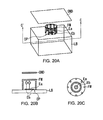
- the entire circumference of the electrodes Ea and Eb excluding the opening OP being the electric field irradiation part does not have to be enclosed by setting the side wall of the conductive frame FM in the form of fences.
- FIGS. 20A to 20C show models of the simulation (referred to as fourth simulation, hereinafter) in case the side wall of the conductive frame FM is set in the form of fences
- FIG. 21 to FIG. 25 show electric field distribution patterns indicative of parts of the result (parts corresponding to the third simulation) obtained by simulating the fourth simulation model under the condition similar to that under which the third simulation is performed.
- the electric field distribution patterns shown in FIG. 21 to FIG. 25 are appended as reference FIG. 7A to reference FIG. 11.
- the frame is not restricted to the case in which the side wall of the conductive frame FM is set in the form of fences.
- the shape of the frame there may be employed the spherical shape, cylindrical shape, conical shape, truncated cone shape, or other arbitrary solid shapes so long as the electric field irradiation direction is opened.
- the shape of the cross-section or the shape of the basal plane of the solid shape is not restricted to the circular shape, and there may be employed the quadrangular shape, hexagonal shape, asteroid shape, or other arbitrary solid shapes.
- a frame that encloses the entire circumference of the paired electrodes excluding the electric field irradiation part, especially, a frame in the formof a cylinder that is defined by the central axis of the electrodes which is perpendicular to a plane on which the electrodes are arranged, and has a basal plane attached to one end of the cylinder, and has its other end of the cylinder which is opposed to the one end of the cylinder opened.
- the waveform of the second signal can be selected on the basis of the first signal such that the potential of the conductive frame is made constant when electric fields are generated from the paired electrodes.
- FIG. 26 shows an electric field distribution pattern by the simulation when the relative dielectric constant is 1800000, while the electrical conductivity is 0 S/m, as the electrical characteristics of the frame.
- FIG. 27 shows an electric field distribution pattern by the simulation when the relative dielectric constant is 20000, while the electrical conductivity is 0 S/m.
- the electric field distribution patterns shown in FIG. 26 and FIG. 27 are appended as reference FIG. 12 and reference FIG. 13.
- the frame is not restricted to a conductor so long as the frame has a constant electrical conductivity.
- the signal output control unit 20 (FIG. 14) is employed, to which the present invention is not restricted, and other units may be widely employed.
- the transformer 27 (FIG. 14) is employed as a unit to generate the first signal output to the electrodes Ea and generate the second signal output to the electrodes Eb such that the phases thereof are made opposite to each other by 180 °.
- the transformer 27 (FIG. 14) is employed as a unit to generate the first signal output to the electrodes Ea and generate the second signal output to the electrodes Eb such that the phases thereof are made opposite to each other by 180 °.
- the transformer 27 (FIG. 14) is employed as indicated by a signal output control unit 40 shown in FIG. 28, there may be employed a non-inverting amplifier circuit 41 and an inverting amplifier circuit 42.
- variable resistors VR1 and VR2 of the non-inverting amplifier circuit 41 and inverting amplifier circuit 42 work as a unit to adjust the amplitude ratio, respectively.
- signals which have their phases made opposite to each other by 180 ° and have their amplitude ratio set to a predetermined value are generated in the signal output control unit 20 and in the signal output control unit 40.
- signals which have the same amplitude and have their phases shifted with respect to each other by a predetermined angle may be employed. In this case, effects similar to those in above-described embodiment can be obtained.
- a signal output control unit that includes a signal generation source that outputs a first signal to the electrode Ea, and a signal generation source that outputs a second signal to the electrode Eb which has its waveform selected on the basis of the first signal such that the potential of the conductive frame FM is set constant when the electric fields are generated from the paired electrodes Ea, Eb.
- a signal generation source that outputs a first signal to the electrode Ea
- a signal generation source that outputs a second signal to the electrode Eb which has its waveform selected on the basis of the first signal such that the potential of the conductive frame FM is set constant when the electric fields are generated from the paired electrodes Ea, Eb.
- the impedance of a living organism is detected using the quasi-electrostatic field, to which the present invention is not restricted, and the present invention can be employed in the case of communicating data in a specific range using the induction field and quasi-electrostatic field.
- influence of interference waves from the outside of the conductive frame FM with respect to the electric field of the communication subject can be reduced, and the electric field of the communication subject can be narrowed down to reception electrodes, which can improve communication efficiency.
- the width of blood vessel (diameter of blood vessel) containing blood and the depth of blood (blood vessel) in the inside of a living organism is described, to which the present invention is not restricted, and the width and depth of the bone marrow tissue containing bone marrow fluid, the width and depth of the cerebrospinal tissue containing cerebrospinal fluid, the width and depth of a lymphatic vessel containing lymph fluid, the width and depth of the large intestine tissue containing flatus, the width and depth of the lung tissue containing pulmonary gas, and tomographic images of various tissues can be determined.
- the ratio of the blood cell component and the blood serum component in blood is determined, to which the present invention is not restricted, and the ratio of the sphere component and the solution component in bone marrow fluid, cerebrospinal fluid, and lymph fluid, and the ratio of the particle component and the solvent component in flatus and pulmonary gas may be determined.
- the present invention can be employed in discriminating a living organism and in judging the state of a living organism.
Landscapes
- Health & Medical Sciences (AREA)
- Life Sciences & Earth Sciences (AREA)
- Heart & Thoracic Surgery (AREA)
- Surgery (AREA)
- Physics & Mathematics (AREA)
- Veterinary Medicine (AREA)
- Biophysics (AREA)
- Pathology (AREA)
- Engineering & Computer Science (AREA)
- Biomedical Technology (AREA)
- Public Health (AREA)
- Medical Informatics (AREA)
- Molecular Biology (AREA)
- General Health & Medical Sciences (AREA)
- Animal Behavior & Ethology (AREA)
- Vascular Medicine (AREA)
- Nuclear Medicine, Radiotherapy & Molecular Imaging (AREA)
- Radiology & Medical Imaging (AREA)
- Hematology (AREA)
- Immunology (AREA)
- Measurement And Recording Of Electrical Phenomena And Electrical Characteristics Of The Living Body (AREA)
- Measurement Of Resistance Or Impedance (AREA)
- Near-Field Transmission Systems (AREA)
Applications Claiming Priority (1)
| Application Number | Priority Date | Filing Date | Title |
|---|---|---|---|
| JP2006112270A JP4210953B2 (ja) | 2006-04-14 | 2006-04-14 | 電界制御装置及び検出装置 |
Publications (3)
| Publication Number | Publication Date |
|---|---|
| EP1844708A2 true EP1844708A2 (de) | 2007-10-17 |
| EP1844708A3 EP1844708A3 (de) | 2010-05-19 |
| EP1844708B1 EP1844708B1 (de) | 2011-11-02 |
Family
ID=38290114
Family Applications (1)
| Application Number | Title | Priority Date | Filing Date |
|---|---|---|---|
| EP07007097A Expired - Fee Related EP1844708B1 (de) | 2006-04-14 | 2007-04-04 | Vorrichtung zur Steuerung und Detektion eines elektrischen Feldes |
Country Status (5)
| Country | Link |
|---|---|
| US (1) | US8340755B2 (de) |
| EP (1) | EP1844708B1 (de) |
| JP (1) | JP4210953B2 (de) |
| KR (1) | KR20070102400A (de) |
| CN (1) | CN100534385C (de) |
Cited By (1)
| Publication number | Priority date | Publication date | Assignee | Title |
|---|---|---|---|---|
| CN113663215A (zh) * | 2021-10-22 | 2021-11-19 | 杭州维纳安可医疗科技有限责任公司 | 电场发生装置及其控制方法、计算机可读存储介质 |
Families Citing this family (15)
| Publication number | Priority date | Publication date | Assignee | Title |
|---|---|---|---|---|
| JP2008287433A (ja) * | 2007-05-16 | 2008-11-27 | Sony Corp | 静脈パターン管理システム、静脈パターン登録装置、静脈パターン認証装置、静脈パターン登録方法、静脈パターン認証方法、プログラムおよび静脈データ構造 |
| JP2008287436A (ja) * | 2007-05-16 | 2008-11-27 | Sony Corp | 静脈パターン管理システム、静脈パターン登録装置、静脈パターン認証装置、静脈パターン登録方法、静脈パターン認証方法、プログラムおよび静脈データ構造 |
| US8814798B2 (en) * | 2008-04-25 | 2014-08-26 | Medtronic, Inc. | Implantable device and method for monitoring venous diameter |
| CN102186413B (zh) * | 2008-09-02 | 2014-10-15 | 奎法克特股份有限公司 | 检测装置、检测方法、静脉感测装置、扫描探针显微镜、变形检测装置和金属检测装置 |
| JP5436554B2 (ja) * | 2009-06-03 | 2014-03-05 | Qファクター株式会社 | 通信装置 |
| JP5394226B2 (ja) * | 2009-12-29 | 2014-01-22 | Qファクター株式会社 | 電界制御装置及び記憶装置 |
| JP2014057117A (ja) * | 2011-01-06 | 2014-03-27 | Univ Of Tokyo | 基準電位生成装置 |
| JP5499184B2 (ja) * | 2011-01-13 | 2014-05-21 | 国立大学法人 東京大学 | 基準電位生成装置 |
| US10413349B2 (en) * | 2011-03-04 | 2019-09-17 | Covidien Lp | System and methods for identifying tissue and vessels |
| JP6083004B2 (ja) * | 2014-01-24 | 2017-02-22 | 国立研究開発法人情報通信研究機構 | 電界検知出力装置 |
| US9884788B2 (en) | 2014-01-31 | 2018-02-06 | Rutgers, The State University Of New Jersey | Method for producing low porosity nonoxide ceramics |
| CN107714039A (zh) * | 2017-09-27 | 2018-02-23 | 上海斐讯数据通信技术有限公司 | 一种基于电子秤检测人体动脉血管硬化的方法及系统 |
| RU181781U1 (ru) * | 2018-04-23 | 2018-07-26 | Федеральное государственное бюджетное образовательное учреждение высшего образования "Омский государственный технический университет" | Датчик напряженности электрического поля |
| RU188242U1 (ru) * | 2018-12-18 | 2019-04-04 | Федеральное государственное бюджетное образовательное учреждение высшего образования "Омский государственный технический университет" (ОмГТУ) | Датчик напряженности электрического поля |
| CN117586882B (zh) * | 2024-01-18 | 2024-05-14 | 柔脉医疗(深圳)有限公司 | 培养容器以及人工血管培养方法 |
Citations (3)
| Publication number | Priority date | Publication date | Assignee | Title |
|---|---|---|---|---|
| DE1126559B (de) | 1955-02-28 | 1962-03-29 | Hans Joachim Schlegel Dr | Geraet zum Messen durchblutungsabhaengiger, pulssynchroner kapazitiver Scheinwiderstandsaenderungen in Zellgeweben in der Tiefe von Hohlorganen menschlicher oder tierischer Lebewesen |
| US4540002A (en) | 1982-04-22 | 1985-09-10 | Dan Atlas | Electrical measuring system particularly useful for the non-invasive examination of biological tissue |
| JP2005073974A (ja) | 2003-08-29 | 2005-03-24 | Sony Corp | 測定装置及びその方法 |
Family Cites Families (8)
| Publication number | Priority date | Publication date | Assignee | Title |
|---|---|---|---|---|
| JPS59148855A (ja) * | 1983-02-15 | 1984-08-25 | I Bii S Kk | 皮表角質層用コンダクタンス測定器 |
| SE466987B (sv) * | 1990-10-18 | 1992-05-11 | Stiftelsen Ct Foer Dentaltekni | Anordning foer djupselektiv icke-invasiv, lokal maetning av elektrisk impedans i organiska och biologiska material samt prob foer maetning av elektrisk impedans |
| AU5671396A (en) * | 1995-05-08 | 1996-11-29 | Massachusetts Institute Of Technology | System for non-contact sensing and signalling using human bo dy as signal transmission medium |
| JP4158097B2 (ja) * | 2003-02-27 | 2008-10-01 | ソニー株式会社 | 認証システム |
| EP1598965A4 (de) | 2003-02-27 | 2008-12-31 | Kiyoaki Takicuchi | Kommunikationssystem |
| JP4088896B2 (ja) | 2003-02-27 | 2008-05-21 | ソニー株式会社 | 通信システム及び通信装置 |
| CN1559343A (zh) * | 2004-02-27 | 2005-01-05 | 中国人民解放军第四军医大学 | 一种用于乳腺包块早期诊断的电阻抗扫描投影成像方法 |
| JP4640608B2 (ja) * | 2005-12-12 | 2011-03-02 | ソニー株式会社 | 検出装置及び検出方法 |
-
2006
- 2006-04-14 JP JP2006112270A patent/JP4210953B2/ja not_active Expired - Fee Related
-
2007
- 2007-04-04 EP EP07007097A patent/EP1844708B1/de not_active Expired - Fee Related
- 2007-04-09 KR KR1020070034536A patent/KR20070102400A/ko not_active Ceased
- 2007-04-12 US US11/783,768 patent/US8340755B2/en not_active Expired - Fee Related
- 2007-04-13 CN CNB2007100982147A patent/CN100534385C/zh not_active Expired - Fee Related
Patent Citations (3)
| Publication number | Priority date | Publication date | Assignee | Title |
|---|---|---|---|---|
| DE1126559B (de) | 1955-02-28 | 1962-03-29 | Hans Joachim Schlegel Dr | Geraet zum Messen durchblutungsabhaengiger, pulssynchroner kapazitiver Scheinwiderstandsaenderungen in Zellgeweben in der Tiefe von Hohlorganen menschlicher oder tierischer Lebewesen |
| US4540002A (en) | 1982-04-22 | 1985-09-10 | Dan Atlas | Electrical measuring system particularly useful for the non-invasive examination of biological tissue |
| JP2005073974A (ja) | 2003-08-29 | 2005-03-24 | Sony Corp | 測定装置及びその方法 |
Cited By (2)
| Publication number | Priority date | Publication date | Assignee | Title |
|---|---|---|---|---|
| CN113663215A (zh) * | 2021-10-22 | 2021-11-19 | 杭州维纳安可医疗科技有限责任公司 | 电场发生装置及其控制方法、计算机可读存储介质 |
| CN113663215B (zh) * | 2021-10-22 | 2022-01-21 | 杭州维纳安可医疗科技有限责任公司 | 电场发生装置及其控制方法、计算机可读存储介质 |
Also Published As
| Publication number | Publication date |
|---|---|
| US20070244409A1 (en) | 2007-10-18 |
| CN101053516A (zh) | 2007-10-17 |
| KR20070102400A (ko) | 2007-10-18 |
| US8340755B2 (en) | 2012-12-25 |
| CN100534385C (zh) | 2009-09-02 |
| JP4210953B2 (ja) | 2009-01-21 |
| EP1844708B1 (de) | 2011-11-02 |
| EP1844708A3 (de) | 2010-05-19 |
| JP2007282789A (ja) | 2007-11-01 |
Similar Documents
| Publication | Publication Date | Title |
|---|---|---|
| US8340755B2 (en) | Electric field control device and detection device | |
| Titze | Interpretation of the electroglottographic signal | |
| Assenheimer et al. | The T-SCANTM technology: electrical impedance as a diagnostic tool for breast cancer detection | |
| Arias et al. | Superheterodyne microwave system for the detection of bioparticles with coplanar electrodes on a microfluidic platform | |
| US7239911B2 (en) | Method for localizing at least one focal lesion in a biological tissue section | |
| EP1615553B1 (de) | Anordnung zur beeinflussung von magnetischen partikeln | |
| US9448187B2 (en) | Imaging using probes | |
| US10716488B2 (en) | Imaging using gated elements | |
| US12310712B2 (en) | Tomographic systems for spatial and temporal control of an electromagnetic field to image a specimen having regions of different dielectric constants | |
| JP2012501779A (ja) | 磁気誘導断層撮影のための方法及びシステム | |
| Ostadrahimi et al. | A novel microwave tomography system based on the scattering probe technique | |
| JP2005073974A (ja) | 測定装置及びその方法 | |
| CN113227773B (zh) | 用于使用导引电磁场确定不均匀样本的区域阻抗特性的方法 | |
| US20200124558A1 (en) | Methods for determining regional impedance characteristics of inhomogenous specimens using guided electromagnetic fields | |
| Min et al. | Comparison of rectangular wave excitations in broad band impedance spectroscopy for microfluidic applications | |
| Feldkamp et al. | Coil geometry effects on scanning single-coil magnetic induction tomography | |
| CN117547242B (zh) | 磁感应断层成像设备 | |
| EP1765160B1 (de) | Gerät zum nachweis von anomalien im körper | |
| Reimer et al. | Image quality analysis and comparison of three radar-based breast microwave sensing systems | |
| Ley et al. | Contrast enhanced UWB microwave breast cancer detection by magnetic nanoparticles | |
| CN112683992B (zh) | 含噪声屏蔽可同时检测磁声信号和电场的定位装置及方法 | |
| JP4390459B2 (ja) | 生物組織部分の病巣の位置検出装置 | |
| Gao et al. | Quasi-static field modeling and validation for intra-body communication | |
| Lin | Mechanisms of Electromagnetic Field Coupling into Biological Systems at ELF and RF Frequencies | |
| Nismayantia et al. | A novel method for measurement of electric field in emulated human body tissue using wire mesh sensor |
Legal Events
| Date | Code | Title | Description |
|---|---|---|---|
| PUAI | Public reference made under article 153(3) epc to a published international application that has entered the european phase |
Free format text: ORIGINAL CODE: 0009012 |
|
| AK | Designated contracting states |
Kind code of ref document: A2 Designated state(s): AT BE BG CH CY CZ DE DK EE ES FI FR GB GR HU IE IS IT LI LT LU LV MC MT NL PL PT RO SE SI SK TR |
|
| AX | Request for extension of the european patent |
Extension state: AL BA HR MK YU |
|
| PUAL | Search report despatched |
Free format text: ORIGINAL CODE: 0009013 |
|
| AK | Designated contracting states |
Kind code of ref document: A3 Designated state(s): AT BE BG CH CY CZ DE DK EE ES FI FR GB GR HU IE IS IT LI LT LU LV MC MT NL PL PT RO SE SI SK TR |
|
| AX | Request for extension of the european patent |
Extension state: AL BA HR MK RS |
|
| 17P | Request for examination filed |
Effective date: 20100806 |
|
| AKX | Designation fees paid |
Designated state(s): DE FR GB |
|
| GRAP | Despatch of communication of intention to grant a patent |
Free format text: ORIGINAL CODE: EPIDOSNIGR1 |
|
| RIC1 | Information provided on ipc code assigned before grant |
Ipc: G01R 27/26 20060101ALI20110510BHEP Ipc: G01N 27/02 20060101ALI20110510BHEP Ipc: A61B 5/053 20060101AFI20110510BHEP |
|
| GRAS | Grant fee paid |
Free format text: ORIGINAL CODE: EPIDOSNIGR3 |
|
| GRAA | (expected) grant |
Free format text: ORIGINAL CODE: 0009210 |
|
| AK | Designated contracting states |
Kind code of ref document: B1 Designated state(s): DE FR GB |
|
| REG | Reference to a national code |
Ref country code: GB Ref legal event code: FG4D |
|
| REG | Reference to a national code |
Ref country code: DE Ref legal event code: R096 Ref document number: 602007018371 Country of ref document: DE Effective date: 20120202 |
|
| PGFP | Annual fee paid to national office [announced via postgrant information from national office to epo] |
Ref country code: DE Payment date: 20120420 Year of fee payment: 6 |
|
| PGFP | Annual fee paid to national office [announced via postgrant information from national office to epo] |
Ref country code: FR Payment date: 20120507 Year of fee payment: 6 Ref country code: GB Payment date: 20120419 Year of fee payment: 6 |
|
| PLBE | No opposition filed within time limit |
Free format text: ORIGINAL CODE: 0009261 |
|
| STAA | Information on the status of an ep patent application or granted ep patent |
Free format text: STATUS: NO OPPOSITION FILED WITHIN TIME LIMIT |
|
| 26N | No opposition filed |
Effective date: 20120803 |
|
| REG | Reference to a national code |
Ref country code: DE Ref legal event code: R097 Ref document number: 602007018371 Country of ref document: DE Effective date: 20120803 |
|
| GBPC | Gb: european patent ceased through non-payment of renewal fee |
Effective date: 20130404 |
|
| PG25 | Lapsed in a contracting state [announced via postgrant information from national office to epo] |
Ref country code: GB Free format text: LAPSE BECAUSE OF NON-PAYMENT OF DUE FEES Effective date: 20130404 Ref country code: DE Free format text: LAPSE BECAUSE OF NON-PAYMENT OF DUE FEES Effective date: 20131101 |
|
| REG | Reference to a national code |
Ref country code: FR Ref legal event code: ST Effective date: 20131231 |
|
| REG | Reference to a national code |
Ref country code: DE Ref legal event code: R119 Ref document number: 602007018371 Country of ref document: DE Effective date: 20131101 |
|
| PG25 | Lapsed in a contracting state [announced via postgrant information from national office to epo] |
Ref country code: FR Free format text: LAPSE BECAUSE OF NON-PAYMENT OF DUE FEES Effective date: 20130430 |