EP1844959A1 - Procédé et machine pour enlever un pneu équipé d'un anneau de roulage à plat interne rigide - Google Patents
Procédé et machine pour enlever un pneu équipé d'un anneau de roulage à plat interne rigide Download PDFInfo
- Publication number
- EP1844959A1 EP1844959A1 EP07106200A EP07106200A EP1844959A1 EP 1844959 A1 EP1844959 A1 EP 1844959A1 EP 07106200 A EP07106200 A EP 07106200A EP 07106200 A EP07106200 A EP 07106200A EP 1844959 A1 EP1844959 A1 EP 1844959A1
- Authority
- EP
- European Patent Office
- Prior art keywords
- axis
- lever
- tyre
- hub
- machine
- Prior art date
- Legal status (The legal status is an assumption and is not a legal conclusion. Google has not performed a legal analysis and makes no representation as to the accuracy of the status listed.)
- Granted
Links
- 238000000034 method Methods 0.000 title claims abstract description 13
- 239000011324 bead Substances 0.000 claims abstract description 40
- 230000008878 coupling Effects 0.000 claims description 5
- 238000010168 coupling process Methods 0.000 claims description 5
- 238000005859 coupling reaction Methods 0.000 claims description 5
- 239000013536 elastomeric material Substances 0.000 description 1
- 238000000605 extraction Methods 0.000 description 1
- 230000005484 gravity Effects 0.000 description 1
- 239000002184 metal Substances 0.000 description 1
Images


Classifications
-
- B—PERFORMING OPERATIONS; TRANSPORTING
- B60—VEHICLES IN GENERAL
- B60C—VEHICLE TYRES; TYRE INFLATION; TYRE CHANGING; CONNECTING VALVES TO INFLATABLE ELASTIC BODIES IN GENERAL; DEVICES OR ARRANGEMENTS RELATED TO TYRES
- B60C25/00—Apparatus or tools adapted for mounting, removing or inspecting tyres
- B60C25/01—Apparatus or tools adapted for mounting, removing or inspecting tyres for removing tyres from or mounting tyres on wheels
- B60C25/05—Machines
- B60C25/132—Machines for removing and mounting tyres
- B60C25/135—Machines for removing and mounting tyres having a tyre support or a tool, movable along wheel axis
- B60C25/138—Machines for removing and mounting tyres having a tyre support or a tool, movable along wheel axis with rotary motion of tool or tyre support
-
- B—PERFORMING OPERATIONS; TRANSPORTING
- B60—VEHICLES IN GENERAL
- B60C—VEHICLE TYRES; TYRE INFLATION; TYRE CHANGING; CONNECTING VALVES TO INFLATABLE ELASTIC BODIES IN GENERAL; DEVICES OR ARRANGEMENTS RELATED TO TYRES
- B60C25/00—Apparatus or tools adapted for mounting, removing or inspecting tyres
- B60C25/01—Apparatus or tools adapted for mounting, removing or inspecting tyres for removing tyres from or mounting tyres on wheels
- B60C25/02—Tyre levers or the like, e.g. hand-held
- B60C25/04—Tyre levers or the like, e.g. hand-held pivotal about the wheel axis, or movable along the rim edge, e.g. rollable
-
- B—PERFORMING OPERATIONS; TRANSPORTING
- B60—VEHICLES IN GENERAL
- B60C—VEHICLE TYRES; TYRE INFLATION; TYRE CHANGING; CONNECTING VALVES TO INFLATABLE ELASTIC BODIES IN GENERAL; DEVICES OR ARRANGEMENTS RELATED TO TYRES
- B60C25/00—Apparatus or tools adapted for mounting, removing or inspecting tyres
- B60C25/01—Apparatus or tools adapted for mounting, removing or inspecting tyres for removing tyres from or mounting tyres on wheels
- B60C25/05—Machines
- B60C25/0509—Machines for inserting additional parts, e.g. support rings, sensors
-
- B—PERFORMING OPERATIONS; TRANSPORTING
- B60—VEHICLES IN GENERAL
- B60C—VEHICLE TYRES; TYRE INFLATION; TYRE CHANGING; CONNECTING VALVES TO INFLATABLE ELASTIC BODIES IN GENERAL; DEVICES OR ARRANGEMENTS RELATED TO TYRES
- B60C25/00—Apparatus or tools adapted for mounting, removing or inspecting tyres
- B60C25/01—Apparatus or tools adapted for mounting, removing or inspecting tyres for removing tyres from or mounting tyres on wheels
- B60C25/05—Machines
- B60C25/0563—Tools interacting with the tyre and moved in relation to the tyre during operation
- B60C25/0578—Tools interacting with the tyre and moved in relation to the tyre during operation hooking only
-
- Y—GENERAL TAGGING OF NEW TECHNOLOGICAL DEVELOPMENTS; GENERAL TAGGING OF CROSS-SECTIONAL TECHNOLOGIES SPANNING OVER SEVERAL SECTIONS OF THE IPC; TECHNICAL SUBJECTS COVERED BY FORMER USPC CROSS-REFERENCE ART COLLECTIONS [XRACs] AND DIGESTS
- Y10—TECHNICAL SUBJECTS COVERED BY FORMER USPC
- Y10T—TECHNICAL SUBJECTS COVERED BY FORMER US CLASSIFICATION
- Y10T29/00—Metal working
- Y10T29/49—Method of mechanical manufacture
- Y10T29/49815—Disassembling
- Y10T29/49822—Disassembling by applying force
Definitions
- the present invention relates to a method and machine for removing a tyre, fitted with a rigid inner run-flat ring, from a relative rim.
- tyre removing machines are known designed to remove a tyre, fitted with a rigid inner run-flat ring, from the relative rim.
- Known tyre removing machines of this sort normally comprise a turntable rotating about an axis; a self-centring clamping device for clamping the rim and relative tyre on, and coaxially with, the turntable; and a hub coaxial and integral with the turntable.
- Known tyre removing machines of this sort normally also comprise a tool column located alongside the turntable, parallel to the turntable axis, and having a number of hydraulic jacks for operating respective tools, which project towards the turntable from the tool column, and are designed to act on the tyre to detach the tyre beads and rigid inner ring beads from the relative flanges on the rim, and to insert, between the rim, on one side, and a tyre bead and corresponding rigid inner ring bead, on the other, one or more levers by which to move said two beads axially outwards of the relative rim flange.
- a method and machine for removing a tyre, fitted with a rigid inner run-flat ring, from a relative rim as claimed in the accompanying independent Claims and, preferably, in any one of the Claims depending directly or indirectly on the independent Claims.
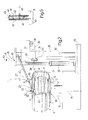
- Number 1 in Figure 2 indicates as a whole a tyre removing machine for removing a tyre 3 of a vehicle wheel 4 from a relative rim 2.
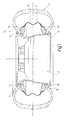
- tyre 3 is a conventional type, and comprises two beads 5 and 6 fitted to respective cylindrical portions 7 and 8 of rim 2 immediately inwards of respective flanges 9 and 10, of which flange 9 is an outer flange.
- Tyre 3 has a known rigid inner run-flat ring 11 comprising a toroidal undulated metal central portion 12; and two beads 13 and 14 made of elastomeric material, fitted to respective axial ends of central portion 12, and fitted to rim 2, adjacent to and inwards of respective beads 5 and 6.
- tyre removing machine 1 comprises a powered turntable 15 having a vertical axis 16 and, on top, a height-adjustable plate 17, which rotates about axis 16, supports wheel 4, and is fitted with a known locating device 18 for engaging flange 10 to lock wheel 4 radially in position, coaxial with axis 16, when rim 2 is placed on plate 17 with flange 10 facing downwards.
- Turntable 15 also has a central hub 19 coaxial with axis 16 and comprising a removable end portion 20 which, in use, projects above flange 9 and provides for locking wheel 4 axially to plate 17.
- End portion 20 comprises a rotary ring 21 coaxial with axis 16, locked axially to hub 19 by a nut 22, and defining an end portion of a connecting device 23, which comprises a fork 24 connected to ring 21 to rotate, with respect to ring 21, about an axis 25 perpendicular to axis 16, and fitted with a front coupling 26 for a tool 27 connectable to hub 19 by connecting device 23 and described in detail below.
- Tyre removing machine 1 also comprises a tool column 28 located alongside turntable 15 and in turn comprising a base 29, from which extends upwards a vertical prismatic guide 30 for a slide 31, which is moved along prismatic guide 30 by a single hydraulic or pneumatic jack 32 interposed between slide 31 and base 29.
- Slide 31 is fitted with a number of known tools - not shown for the sake of simplicity, and hereinafter referred to as "disriding tools" - which act on tyre 3 to detach bead 5 from flange 9 and extract bead 5 from rim 2.
- a bracket 33 projects laterally outwards from a bottom portion of slide 31, and is fitted on its free end, by means of a hinge 34 with an axis 35 parallel to axis 16, with a pressure tool 36 comprising an elbow lever 37, one end of which is connected to bracket 33, and the other end of which is fitted with an upward-sloping pin fitted in rotary manner with a plate 38, the periphery of which lies in a plane sloping slightly upwards towards axis 16.
- the angular position of pressure tool 36 about axis 35 and, therefore, the distance between plate 38 and axis 16 are controllable by a brace 39 ( Figure 7) adjustable in length and interposed between slide 31 and an intermediate portion of lever 37.
- tool 27 comprises a lever 40, a first end of which is connected removably to fork 24 by front coupling 26, and a second end of which extends over slide 31 and through a portal 41 integral with slide 31 and extending upwards from the top end of slide 31.
- portal 41 comprises two substantially vertical posts 42 joined by a top cross member 43 and defining between them a gap 44, which lies in a radial plane P ( Figure 7) with respect to axis 15, is engaged, in use, by lever 37, and is divided into two parts by a pin 45 parallel to cross member 43 and fitted removably through intermediate portions of posts 42.
- lever 40 comprises a first end fitted removably to front coupling 26 of connecting device 23; a second end extending through gap 44; and an intermediate portion defined by a prismatic guide 46 for fitting, in an adjustable position along lever 40, an intermediate portion of a rod 47 positioned crosswise to lever 40 and extending in radial plane P.
- rod 47 comprises a first end defined by a hook 48, which faces radially outwards with respect to axis 16 when lever 40 is attached to connecting device 23; and a second end above the first end, in use, and fitted with a bracket 49 perpendicular to lever 40 and fitted on its free end with a known toggle tappet 50 comprising a tappet roller 51, which is movable, by a hand lever 52, from a raised rest position (shown by the dash line in Figure 5) to a lowered work position (shown by the continuous line in Figure 5), in which tappet roller 51 rests, in use, on flange 9 to keep hook 48 in such an axial position, with respect to rim 2, that a portion of bead 13, when engaged by hook 48, is positioned and maintained axially outwards of flange 9.
- a known toggle tappet 50 comprising a tappet roller 51, which is movable, by a hand lever 52, from a raised rest position (shown by the dash line in Figure 5) to
- lever 40 is fitted to front coupling 26, and rod 47 is locked in position on lever 40 so that the distance between hook 48 and axis 25 is approximately equal to but no less than the radius of flange 9.
- the other end of lever 40 is inserted through gap 44 of portal 41, which is fitted with pin 45 and maintained by slide 31 in a raised position ( Figure 2), in which lever 40 rests on a front edge of slide 31 at the base of portal 41.
- jack 32 is operated to lower slide 31, which takes lever 40 with it, by force of gravity, until hook 48 contacts tyre 3 just outside flange 9.
- hook 48 contacts tyre 3 just outside flange 9.
- downward rotation of lever 40 in radial plane P is arrested until, as slide 31 continues moving down into a lowered position not shown, pin 45 comes into contact with lever 40 and draws it down further to insert hook 48 inwards of both bead 5 of tyre 3 and bead 13 of rigid ring 11.
- pressure tool 36 is positioned just below tyre 3, and can be fixed, by adjusting the length of brace 39, so that the periphery of plate 38 is positioned tangent to bead 6, just outwards of flange 10, and substantially in radial plane P.
- Jack 32 is then operated again to move slide 31 back into the raised position in Figure 2. Over a first part of this movement, lever 40 remains in the Figure 9 engaged position, and is simply released by pin 45, whereas pressure tool 36 acts on the tyre to unseat beads 6 and 14 upwards (Figure 10). On eventually contacting the front edge of slide 31, lever 40 is also raised, by rotating about axis 25 in radial plane P, and, in so doing, draws a portion of bead 13 outwards of and over flange 9 ( Figure 10).
- toggle tappet 50 until now in the rest position shown by the dash line in Figure 5, is moved, using hand lever 52, into the work position shown by the continuous line in Figure 5, and in which tappet roller 51 faces flange 9.
- a slight downward movement of slide 31 at this point brings tappet roller 51 to rest firmly on flange 9, and detaches lever 40 from the front edge of slide 31.
- lever 40 When turntable 15, at this point, is operated, and lever 40 simultaneously locked angularly in radial plane P by portal 41, tappet roller 51 rolls along the whole of flange 9 to extract the whole of bead 13 from flange 9. At this point, lever 40 can be removed, and slide 31 moved into the fully-raised position, to allow pressure tool 36 to remove the whole of tyre 3 and rigid ring 11 off rim 2.
- one jack 32 can be used for all the operations involved in removing tyre 3 and rigid ring 11 off rim 2.
Landscapes
- Engineering & Computer Science (AREA)
- Mechanical Engineering (AREA)
- Tires In General (AREA)
- Tyre Moulding (AREA)
- Separation, Recovery Or Treatment Of Waste Materials Containing Plastics (AREA)
Applications Claiming Priority (1)
| Application Number | Priority Date | Filing Date | Title |
|---|---|---|---|
| IT000284A ITTO20060284A1 (it) | 2006-04-14 | 2006-04-14 | Metodo e macchina per lo smontaggio di uno pneumatico provvisto di un anello rigido interno anti-appiattimento |
Publications (2)
| Publication Number | Publication Date |
|---|---|
| EP1844959A1 true EP1844959A1 (fr) | 2007-10-17 |
| EP1844959B1 EP1844959B1 (fr) | 2009-03-11 |
Family
ID=38269057
Family Applications (1)
| Application Number | Title | Priority Date | Filing Date |
|---|---|---|---|
| EP07106200A Not-in-force EP1844959B1 (fr) | 2006-04-14 | 2007-04-14 | Procédé et machine pour enlever un pneu équipé d'un anneau de roulage à plat interne rigide |
Country Status (5)
| Country | Link |
|---|---|
| US (1) | US7946016B2 (fr) |
| EP (1) | EP1844959B1 (fr) |
| DE (1) | DE602007000655D1 (fr) |
| ES (1) | ES2322674T3 (fr) |
| IT (1) | ITTO20060284A1 (fr) |
Families Citing this family (6)
| Publication number | Priority date | Publication date | Assignee | Title |
|---|---|---|---|---|
| ITMO20060398A1 (it) * | 2006-12-04 | 2008-06-05 | Gino Ferrari | Apparato per macchine smontagomme |
| WO2009148544A2 (fr) | 2008-05-29 | 2009-12-10 | Djm Technologies, Llc | Machine de démontage et de montage d'anneau de soutien pour pneumatique anti-crevaison |
| WO2010110864A2 (fr) * | 2009-03-25 | 2010-09-30 | Carawan James R | Machine de retrait et d'installation d'un anneau pour pneu à flancs renforcés |
| IT1396144B1 (it) * | 2009-11-03 | 2012-11-16 | Corghi Spa | Dispositivo di sollevamento di un fianco inferiore di uno pneumatico, in una macchina smontagomme. |
| US20160287640A1 (en) * | 2014-12-31 | 2016-10-06 | Applied Biologics, Llc | Denuded amnion flowable tissue graft and method of forming same |
| WO2022187508A1 (fr) * | 2021-03-03 | 2022-09-09 | Cushcore, Inc. | Outil et procédé d'installation et de retrait de pneu |
Citations (5)
| Publication number | Priority date | Publication date | Assignee | Title |
|---|---|---|---|---|
| US2850061A (en) * | 1955-02-25 | 1958-09-02 | Harry G Twiford | Center post for tire changer |
| US2940514A (en) * | 1956-12-06 | 1960-06-14 | Robert D Henderson | Tire demounting tool |
| US3847198A (en) * | 1973-01-30 | 1974-11-12 | Magnum Automotive Equip | Centerpost drive mechanism |
| US4586551A (en) * | 1985-04-09 | 1986-05-06 | Big Four Equipment, Inc. | Centerpost drive for a tire changing machine |
| EP1236589A2 (fr) * | 2001-02-28 | 2002-09-04 | Societa' Italiana Costruzioni Elettromeccaniche - S.I.C.E. - S.P.A. | Dispositif amélioré pour le montage et le démontage de pneus avec appui de sécurité du type "system pax" et similaires |
Family Cites Families (1)
| Publication number | Priority date | Publication date | Assignee | Title |
|---|---|---|---|---|
| US2746528A (en) * | 1953-01-26 | 1956-05-22 | Lee J Damman | Tire remover with a rotatable wheel support |
-
2006
- 2006-04-14 IT IT000284A patent/ITTO20060284A1/it unknown
-
2007
- 2007-04-13 US US11/785,001 patent/US7946016B2/en not_active Expired - Fee Related
- 2007-04-14 DE DE602007000655T patent/DE602007000655D1/de not_active Expired - Fee Related
- 2007-04-14 ES ES07106200T patent/ES2322674T3/es active Active
- 2007-04-14 EP EP07106200A patent/EP1844959B1/fr not_active Not-in-force
Patent Citations (5)
| Publication number | Priority date | Publication date | Assignee | Title |
|---|---|---|---|---|
| US2850061A (en) * | 1955-02-25 | 1958-09-02 | Harry G Twiford | Center post for tire changer |
| US2940514A (en) * | 1956-12-06 | 1960-06-14 | Robert D Henderson | Tire demounting tool |
| US3847198A (en) * | 1973-01-30 | 1974-11-12 | Magnum Automotive Equip | Centerpost drive mechanism |
| US4586551A (en) * | 1985-04-09 | 1986-05-06 | Big Four Equipment, Inc. | Centerpost drive for a tire changing machine |
| EP1236589A2 (fr) * | 2001-02-28 | 2002-09-04 | Societa' Italiana Costruzioni Elettromeccaniche - S.I.C.E. - S.P.A. | Dispositif amélioré pour le montage et le démontage de pneus avec appui de sécurité du type "system pax" et similaires |
Also Published As
| Publication number | Publication date |
|---|---|
| US20080010804A1 (en) | 2008-01-17 |
| US7946016B2 (en) | 2011-05-24 |
| EP1844959B1 (fr) | 2009-03-11 |
| DE602007000655D1 (de) | 2009-04-23 |
| ITTO20060284A1 (it) | 2007-10-15 |
| ES2322674T3 (es) | 2009-06-24 |
Similar Documents
| Publication | Publication Date | Title |
|---|---|---|
| EP2629992B1 (fr) | Machine de démontage de pneu | |
| EP2233325A1 (fr) | Machine pour placer et enlever des pneus de jantes de véhicules | |
| JP5069830B2 (ja) | 自動タイヤ取外し及び取付装置とその装置を備えたタイヤ取外し機 | |
| EP1897708B1 (fr) | Machine pour placer et supprimer des pneus et jantes de véhicules | |
| EP1714807A1 (fr) | Outil pour le démontage ou montage automatique de pneumatique sur/ d' une jante | |
| EP2599648B1 (fr) | Tête fonctionnelle pour placer et supprimer des pneus sur jantes de véhicules | |
| US7946016B2 (en) | Method and machine for removing a tyre fitted with a rigid inner run-flat ring | |
| US8464775B2 (en) | Tool for tire uninstalling and installing machines | |
| EP1459913B1 (fr) | Dispositif de montage et démontage de pneumatiques | |
| EP2995478B1 (fr) | Machine destinée à monter et à démonter des pneus de roues de véhicules | |
| EP1844960B1 (fr) | Machine pour monter et démonter un pneu équipé d'un anneau de roulage à plat interne rigide | |
| EP0805053A2 (fr) | Machine pour le montage et le démontage de pneus des jantes de roues | |
| US20230123205A1 (en) | Machine for mounting and demounting a tyre relative to a corresponding rim and wheel servicing method | |
| US8381791B2 (en) | Device for lifting a bottom side wall of a tyre in a tyre removing machine | |
| EP2756969B1 (fr) | Machine destinée à démonter des pneus de jantes de véhicules ou destinée à monter des pneus sur une jante de véhicule | |
| EP2988957B1 (fr) | Machine de changement de pneu | |
| US9610812B2 (en) | Tire bead extraction device for tire-changing machines | |
| CN205890424U (zh) | 用于车辆的车轮轮胎的拆卸和装配的机器 | |
| US20080251176A1 (en) | Method and unit for mounting on a rim a tire provided with a safety support |
Legal Events
| Date | Code | Title | Description |
|---|---|---|---|
| PUAI | Public reference made under article 153(3) epc to a published international application that has entered the european phase |
Free format text: ORIGINAL CODE: 0009012 |
|
| AK | Designated contracting states |
Kind code of ref document: A1 Designated state(s): AT BE BG CH CY CZ DE DK EE ES FI FR GB GR HU IE IS IT LI LT LU LV MC MT NL PL PT RO SE SI SK TR |
|
| AX | Request for extension of the european patent |
Extension state: AL BA HR MK YU |
|
| 17P | Request for examination filed |
Effective date: 20080331 |
|
| AKX | Designation fees paid |
Designated state(s): DE ES FR GB |
|
| GRAP | Despatch of communication of intention to grant a patent |
Free format text: ORIGINAL CODE: EPIDOSNIGR1 |
|
| GRAS | Grant fee paid |
Free format text: ORIGINAL CODE: EPIDOSNIGR3 |
|
| GRAA | (expected) grant |
Free format text: ORIGINAL CODE: 0009210 |
|
| AK | Designated contracting states |
Kind code of ref document: B1 Designated state(s): DE ES FR GB |
|
| REG | Reference to a national code |
Ref country code: GB Ref legal event code: FG4D |
|
| REF | Corresponds to: |
Ref document number: 602007000655 Country of ref document: DE Date of ref document: 20090423 Kind code of ref document: P |
|
| REG | Reference to a national code |
Ref country code: ES Ref legal event code: FG2A Ref document number: 2322674 Country of ref document: ES Kind code of ref document: T3 |
|
| PGFP | Annual fee paid to national office [announced via postgrant information from national office to epo] |
Ref country code: ES Payment date: 20090430 Year of fee payment: 3 |
|
| PGFP | Annual fee paid to national office [announced via postgrant information from national office to epo] |
Ref country code: DE Payment date: 20090430 Year of fee payment: 3 Ref country code: FR Payment date: 20090430 Year of fee payment: 3 |
|
| PLBE | No opposition filed within time limit |
Free format text: ORIGINAL CODE: 0009261 |
|
| STAA | Information on the status of an ep patent application or granted ep patent |
Free format text: STATUS: NO OPPOSITION FILED WITHIN TIME LIMIT |
|
| 26N | No opposition filed |
Effective date: 20091214 |
|
| REG | Reference to a national code |
Ref country code: FR Ref legal event code: ST Effective date: 20101230 |
|
| PG25 | Lapsed in a contracting state [announced via postgrant information from national office to epo] |
Ref country code: DE Free format text: LAPSE BECAUSE OF NON-PAYMENT OF DUE FEES Effective date: 20101103 |
|
| REG | Reference to a national code |
Ref country code: ES Ref legal event code: FD2A Effective date: 20110708 |
|
| PG25 | Lapsed in a contracting state [announced via postgrant information from national office to epo] |
Ref country code: ES Free format text: LAPSE BECAUSE OF NON-PAYMENT OF DUE FEES Effective date: 20110628 |
|
| PG25 | Lapsed in a contracting state [announced via postgrant information from national office to epo] |
Ref country code: ES Free format text: LAPSE BECAUSE OF NON-PAYMENT OF DUE FEES Effective date: 20100415 |
|
| GBPC | Gb: european patent ceased through non-payment of renewal fee |
Effective date: 20110414 |
|
| PG25 | Lapsed in a contracting state [announced via postgrant information from national office to epo] |
Ref country code: GB Free format text: LAPSE BECAUSE OF NON-PAYMENT OF DUE FEES Effective date: 20110414 |
|
| PG25 | Lapsed in a contracting state [announced via postgrant information from national office to epo] |
Ref country code: FR Free format text: LAPSE BECAUSE OF NON-PAYMENT OF DUE FEES Effective date: 20100430 |