EP1845882B1 - Préhenseur commandé par poussoir pour rétracteur chirurgical - Google Patents
Préhenseur commandé par poussoir pour rétracteur chirurgical Download PDFInfo
- Publication number
- EP1845882B1 EP1845882B1 EP20060719331 EP06719331A EP1845882B1 EP 1845882 B1 EP1845882 B1 EP 1845882B1 EP 20060719331 EP20060719331 EP 20060719331 EP 06719331 A EP06719331 A EP 06719331A EP 1845882 B1 EP1845882 B1 EP 1845882B1
- Authority
- EP
- European Patent Office
- Prior art keywords
- grasper
- holder
- activator
- push
- gear
- Prior art date
- Legal status (The legal status is an assumption and is not a legal conclusion. Google has not performed a legal analysis and makes no representation as to the accuracy of the status listed.)
- Expired - Lifetime
Links
Images


Classifications
-
- A—HUMAN NECESSITIES
- A61—MEDICAL OR VETERINARY SCIENCE; HYGIENE
- A61B—DIAGNOSIS; SURGERY; IDENTIFICATION
- A61B90/00—Instruments, implements or accessories specially adapted for surgery or diagnosis and not covered by any of the groups A61B1/00 - A61B50/00, e.g. for luxation treatment or for protecting wound edges
- A61B90/50—Supports for surgical instruments, e.g. articulated arms
-
- A—HUMAN NECESSITIES
- A61—MEDICAL OR VETERINARY SCIENCE; HYGIENE
- A61B—DIAGNOSIS; SURGERY; IDENTIFICATION
- A61B17/00—Surgical instruments, devices or methods
- A61B17/02—Surgical instruments, devices or methods for holding wounds open, e.g. retractors; Tractors
-
- A—HUMAN NECESSITIES
- A61—MEDICAL OR VETERINARY SCIENCE; HYGIENE
- A61B—DIAGNOSIS; SURGERY; IDENTIFICATION
- A61B17/00—Surgical instruments, devices or methods
- A61B2017/00367—Details of actuation of instruments, e.g. relations between pushing buttons, or the like, and activation of the tool, working tip, or the like
-
- Y—GENERAL TAGGING OF NEW TECHNOLOGICAL DEVELOPMENTS; GENERAL TAGGING OF CROSS-SECTIONAL TECHNOLOGIES SPANNING OVER SEVERAL SECTIONS OF THE IPC; TECHNICAL SUBJECTS COVERED BY FORMER USPC CROSS-REFERENCE ART COLLECTIONS [XRACs] AND DIGESTS
- Y10—TECHNICAL SUBJECTS COVERED BY FORMER USPC
- Y10T—TECHNICAL SUBJECTS COVERED BY FORMER US CLASSIFICATION
- Y10T292/00—Closure fasteners
- Y10T292/08—Bolts
- Y10T292/1043—Swinging
- Y10T292/1075—Operating means
- Y10T292/1079—Gear
Definitions
- This invention relates generally to a grasper for a retractor, and more particularly, to a push-button activated grasper for a surgical retractor.
- U.S. patent application US 1,679,902 A discloses a tire chain lock comprising a grasper body having a first surface defining an opening to accept a detachable link, and a gear-actuated holder connected to the grasper body and configured to move from a first position to a second position, the first position being located at least partially in the opening to provide for retaining the detachable link in the opening.
- U.S. patent application US 1,626,866 A discloses a safety hook comprising a grasper body having a first surface defining an opening to accept a cable, and a gear-actuated holder connected to the grasper body and configured to move from a first position to a second position, the first position being located at least partially in the opening to provide for retaining the cable in the opening, and an activator at least partially seated within the grasper body and operably connected to the gear-actuated holder, the activator having a gear member to actuate the holder.
- the present invention provides a side-loading push-button activated grasper for a surgical retractor as defined in claim 1.
- the grasper has a grasper body, an activator, and a holder to releasably retain a connector head of, for example, a retractor blade.
- the holder is configured to move from a first position, located at least partially in the opening to provide for retaining the connector head in the opening, to a second position wherein the connector head may be removed.
- the grasper body has a first surface defining an opening to accept a connector head, and a gear-actuated holder connected to the body and configured to move from a first position to a second position.
- a push-button activator is provided and is seated partially within the grasper body and operably connected to the gear-actuated holder.
- the push-button activator has a gear member to actuate the holder from the first position to the second position.
- the activator has a gear track with engaging mating members to actuate the holder.
- the push-button activator has a longitudinal axis that is transverse to a longitudinal axis of the grasper body, and the push-button activator travels about its longitudinal axis. Further, the push-button activator moves from a normal position to an activated position, thereby manipulating the holder from the first position to the second position.
- a spring is provided within the grasper body. The spring engages the push-button activator to bias the push-button activator to the normal position.
- an actuating member is provided between the push-button activator and the holder.
- the actuating member engages both the gear track on the push-button activator and the holder to translate motion from the push-button activator to the holder.
- the actuating member is a gear that rotates about a shaft located in a cavity within the grasper body.
- the holder is rotatedly connected to the grasper body.
- the holder has at least one engaging member adapted to be driven by the gear track on the push-button activator.
- a rib extends from the first surface of the grasper body into the opening.
- another rib extends from the holder and is dimensioned to cooperate with the rib extending from the first surface of the grasper body. The ribs are adapted to mate with a groove in the connector head.
- the grasper 10 is push-button activated.
- the grasper 10 comprises a grasper body 12, an activator 14, a holder 16, an actuating member 18, a spring 20 and a pin 22.
- the grasper body 12 has an opening 24 which is configured to accept a connector head 26 for a retractor blade or other retractor component (not shown).
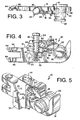
- the holder 16 is configured to move from a first or normal position (generally shown in FIGS. 1-4 ) to a second or actuated position (generally shown in FIGS. 5 and 6 ).
- a portion of the holder 16 is located at least partially in the opening 24 to provide for retaining the connector head 26 in a seated position in the opening 24 of the grasper 10.
- the holder 16 is configured to allow the connector head 26 to be removed from the grasper 10.
- the grasper body 12 comprises a unitary component having a first cavity 28 and a second cavity 30.
- the first cavity 28 houses the spring 20, the pin 22 and a portion of the activator 14, and the second cavity 30 houses the actuating member 18 and a portion of the holder 16.
- the first cavity 28 is joined to the second cavity 30.
- the grasper body 12 also has an opening 24 defined by a first surface 32 thereof.
- the opening 24 is generally U-shaped and has an arcuate portion to mate with the cylindrical or arcuate shape of the connector head 26. Further, the opening 24 provides a side-loading socket for accepting the connector head 26 adjacent the first surface 32 of the grasper body 12. Accordingly, the opening 24 is dimensioned to receive, retain and release the connector head 26.
- a rib 34 extends from the first surface 32 of the grasper body 12 and into the opening 24 thereof. The rib 34 generally mates with a corresponding groove 36 on the connector head 26 when the connector head 26 is side-inserted into the opening 24. In one embodiment, such as shown in FIG.
- the holder 16 also has a similar rib 38 extending from its outer surface.
- the rib 38 of the holder 16 is dimensioned to cooperate with the rib 34 extending from the first surface 32 of the grasper body 12 to mate with the corresponding groove 36 on the connector head 26 and thereby seat the connector head 26 in the opening 24 of the grasper body 12.
- the ribs 34 and 38 may extend any desired length about their respective extending surfaces. Further, by their physical protrusion into the opening 24 of the grasper body 12, one of ordinary skill in the art would readily understand that the ribs 34 and 36, both independently and collectively, operate to prohibit top loading of the connector head. In an alternate embodiment, however, the holder 16 does not have a rib 34, but rather only has a cam surface 65.
- the entrance to the opening 24 has a chamfered or beveled portion 25 as a lead-in to assist in seating the connector head 26 in the opening 24 of the grasper body 12.
- the grasper body 12 has a proximal end 40 and a distal end 42, and a longitudinal axis that extends generally from the proximal end 40 to the distal end 42.
- the opening 24 is provided generally adjacent the distal end 42 of the grasper body 12, and a pair of attachment arms 44 are provided at the proximal end 40 of the grasper body 12.
- the attachment arms 44 provide a means for connecting the grasper 10 to a retractor arm (not shown). Further, in this embodiment the arms 44 have openings 46 into which a bolt or other fastener is inserted to hingedly connect the grasper 10 to the retractor. As such, the grasper 10 may be rotated about the fastener arm to allow the grasper 10 to be positioned closer to the surgical site. Additionally, this embodiment of the grasper body 12 has a suture hole 48 to permit the retractor arms to be sutured in place and thereby to assist in preventing movement of the retractor after the retractor is positioned by the operator.
- the first cavity 28 of the grasper body 12 houses the spring 20, the pin 22 and a portion of the activator 14.
- the activator 14 is a push-button member 14 that manipulates the holder 16 to provide for selectively retaining and releasing the connector head 26.
- the spring 20 is generally a compression spring. A first end of the spring 20 is provided against the bottom of the first cavity 28, and a second end of the spring 20 is provided against the push button activator 14 to exert an upward force on the push-button activator 14.
- the bottom of the push-button activator 14 has a bore 56 to position and retain the second end of the spring 20 therein.
- the push-button activator 14 is at least partially seated within the grasper body 12, extends transversely from the grasper body 12, and is operable connected to the holder 16 to move the holder 16 from the normal position to the actuated position.
- the push-button activator 14 is a generally cylindrical component having a gear member to actuate the holder 16, an opposing recess 52 on its outer surface, a shoulder 54 at its first end and a bore 56 at its second end.
- the gear member is a gear track 50.
- the activator 14 has a longitudinal axis that extends from its first end to its second end, and it is understood that in this embodiment the activator 14 travels about its longitudinal axis.
- the longitudinal axis of the activator 14 is transverse to a longitudinal axis of the grasper body 12.
- the recess 52 has a first shoulder 58 and a second shoulder 60, and the pin 22 in the first cavity 28 of the grasper body 12 operates as both a guide and a stop for the push-button activator 14.
- the spring 20 engages the activator 14 by exerting an upward force on the activator 14 to bias the activator 14 to the normal position.
- the activator 14 When the operator actuates the grasper 10 by pushing downward on the activator 14 to overcome the force of the spring 20, see FIG. 6 , the activator 14 is pushed further into the first cavity 28 until either the second shoulder 60 of the activator recess 52 engages the pin 22, or the shoulder 54 of the activator 14 bottoms out on a counter-bore of the first cavity 28. This is referred to as the actuated position.
- the pin 22 also operates as a cam for the activator 14, and the surfaces of the recess 52 operate as the cam follower. In a preferred embodiment, the pin 22 extends from one side of the grasper body 12 to the opposing side thereof.
- the gear track 50 of the actuator opposes the recess 52.
- the gear track 50 of the activator 14 generally comprises a plurality of gear teeth which are adapted to engage mating members to actuate the holder 16.
- the gear track 50 of the activator 14 is linear, however, it is understood that any geometry of a gear, pulley, rack, pinion, or other drive mechanism is possible without departing from the scope of the present invention.
- the holder 16 is rotatedly connected to the grasper body 12 within the second cavity 30 thereof.
- a first shaft 62 extends from one side of the grasper body 12 to the opposing side of the grasper body 12 to rotatedly support the holder 16.
- the holder 16 has a plurality of engaging members 64, such as gear teeth, extending therefrom which are adapted to be driven by the activator 14.
- the holder 16 also has an outer surface that may operate as a cam surface 65, and a rib 38 extending from its outer surface.
- the outer surface 65 generally has an arcuate shape, and in one embodiment the outer surface 65 has a convex shape thereto.
- the rib 38 of the holder 16 is dimensioned to cooperate with the rib 34 extending from the first surface 32 of the grasper body 12 to mate with the corresponding groove 36 on the connector head 26 and thereby seat the connector head 26 in the opening 24 of the grasper body 12.
- an actuating member 18 may be provided to assist in translating motion from the activator 14 to the holder 16.
- the actuating member 18 is generally positioned in the second cavity 30 and between the activator 14 and the holder 16.
- the actuating member 18 is a gear 66 that rotates about a second shaft 68 extending between the opposing sides of the grasper body 12.
- the actuating member 18 engages both the gear track 50 on the activator 14 and the engaging members 64 on the holder 16.
- the holder 16 is positively driven by actuation of the activator 14.
- the holder 16 is defined as being gear actuated.
- the spring 20 is inserted into the first cavity 28 of the grasper body 12 such that the first end of the spring 20 is positioned against the bottom of the first cavity 28.
- the activator 14 is then inserted into the first cavity 28 and the second end of the spring 20 is positioned in the bore 56 at the second end of the activator 14.
- the pin 22 is inserted through an aperture 70 in the sidewall of the grasper body 12 and positioned against or adjacent the cam follower surface of the recess 52 of the activator 14.
- the pin 22 operates to moveably secure the activator 14 within the first cavity 28 of the grasper body 12.
- the first and second shafts 62 and 68 are then inserted into the respective retaining apertures 72 in the side wall of the grasper body 12.
- the actuating member 18 is fitted onto the second shaft 68, such that the engaging members of the actuator 18 engage the gear track 50 of the activator 14.
- the holder 16 is fitted onto the first shaft 62 such that the engaging members 64 of the holder 64 engage the engaging members of the actuating member 18.
- the cap 74 is positioned on the opposing ends of the first and second shafts 62 and 68 and closes off the side of the second cavity 30, thereby securing the actuating member 18 and the holder 16 in axial place.
- Each of the shafts and the cap 74 are then laser welded to the grasper body 12 and the entire grasper 10 is surface ground and polished.
- the normal state of the grasper 10 has the holder 16 extending at least partially in the opening 24 of the grasper body 12.
- a connector head 26 would be retained in the opening 24 and the ribs 34 and 38 of the holder 16 and the grasper body 12 would cooperate to mate with the corresponding groove 36 on the connector head 26 and thereby seat the connector head 26 in the opening 24 of the grasper body 12.
- an operator would push down on the push-button activator 14.
- the gear track 50 drives the actuating member gear 18 which in turn drives the engaging members of the holder 16 to rotate the holder 16 into the second position such that the connector head 26 can be removed from the grasper 10.
- each of the components of the grasper 10 are made of a material that is easily sanitized and provides good wear characteristics, such as stainless steel or titanium, however it is understood by one of ordinary skill in the art that the components of the grasper 10 may be made of any rigid material.
Landscapes
- Health & Medical Sciences (AREA)
- Surgery (AREA)
- Life Sciences & Earth Sciences (AREA)
- Heart & Thoracic Surgery (AREA)
- Molecular Biology (AREA)
- Oral & Maxillofacial Surgery (AREA)
- Engineering & Computer Science (AREA)
- Biomedical Technology (AREA)
- Nuclear Medicine, Radiotherapy & Molecular Imaging (AREA)
- Medical Informatics (AREA)
- Pathology (AREA)
- Animal Behavior & Ethology (AREA)
- General Health & Medical Sciences (AREA)
- Public Health (AREA)
- Veterinary Medicine (AREA)
- Surgical Instruments (AREA)
- Details Of Spanners, Wrenches, And Screw Drivers And Accessories (AREA)
Claims (10)
- Préhenseur commandé par poussoir (10) pour un rétracteur chirurgical, le préhenseur comprenant :un corps de préhenseur (12) ayant une première surface définissant une ouverture (24) pour accepter une tête de connecteur (26) ;un organe de retenue actionné par engrenage (16) relié au corps de préhenseur (12) et configuré pour se déplacer d'une première position à une seconde position, la première position étant située au moins partiellement dans l'ouverture (24) pour assurer la retenue de la tête de connecteur (26) dans l'ouverture (24) ; etun actionneur à poussoir (14) au moins partiellement reçu à l'intérieur du corps de préhenseur (12) et relié de façon fonctionnelle à l'organe de retenue actionné par engrenage (16), l'actionneur à poussoir (14) ayant un élément denté pour actionner l'organe de retenue (16).
- Préhenseur selon la revendication 1, comprenant en outre un actionneur ayant une crémaillère (50), la crémaillère étant en prise avec des éléments conjugués pour actionner l'organe de retenue (16).
- Préhenseur selon la revendication 2, comprenant en outre un roue dentée (66) entre l'actionneur (14) et l'organe de retenue (16), la roue dentée (66) étant en prise avec l'actionneur et l'organe de retenue pour transmettre un mouvement de l'actionneur à l'organe de retenue.
- Préhenseur selon la revendication 1, dans lequel l'organe de retenue (16) est relié de façon rotative au corps de préhenseur (12).
- Préhenseur selon la revendication 1, dans lequel l'actionneur à poussoir (14) a un axe longitudinal qui est transversal à un axe longitudinal du corps de préhenseur (12).
- Préhenseur selon la revendication 5, dans lequel l'actionneur à poussoir (14) se déplace autour de son axe longitudinal.
- Préhenseur selon la revendication 6, dans lequel l'actionneur à poussoir (14) se déplace d'une position normale à une position actionnée, manipulant ainsi l'organe de retenue (16) de la première position à la seconde position.
- Préhenseur selon la revendication 7, comprenant en outre un ressort (20) à l'intérieur du corps de préhenseur (12) et engagé avec l'actionneur à poussoir (14) pour solliciter l'actionneur à poussoir vers la position normale.
- Préhenseur selon la revendication 1, comprenant en outre une nervure s'étendant d'une première surface du corps de préhenseur (12) dans l'ouverture (24).
- Préhenseur selon la revendication 9, comprenant en outre une nervure s'étendant à partir de l'organe de retenue (16) et dimensionnée pour coopérer avec la nervure s'étendant à partir de la première surface du corps de préhenseur (12).
Applications Claiming Priority (2)
| Application Number | Priority Date | Filing Date | Title |
|---|---|---|---|
| US11/052,543 US7473223B2 (en) | 2005-02-07 | 2005-02-07 | Push-button activated grasper for surgical retractor |
| PCT/US2006/002431 WO2006086148A2 (fr) | 2005-02-07 | 2006-01-23 | Prehenseur commande par poussoir pour retracteur chirurgical |
Publications (2)
| Publication Number | Publication Date |
|---|---|
| EP1845882A2 EP1845882A2 (fr) | 2007-10-24 |
| EP1845882B1 true EP1845882B1 (fr) | 2015-04-15 |
Family
ID=36485582
Family Applications (1)
| Application Number | Title | Priority Date | Filing Date |
|---|---|---|---|
| EP20060719331 Expired - Lifetime EP1845882B1 (fr) | 2005-02-07 | 2006-01-23 | Préhenseur commandé par poussoir pour rétracteur chirurgical |
Country Status (3)
| Country | Link |
|---|---|
| US (2) | US7473223B2 (fr) |
| EP (1) | EP1845882B1 (fr) |
| WO (1) | WO2006086148A2 (fr) |
Families Citing this family (68)
| Publication number | Priority date | Publication date | Assignee | Title |
|---|---|---|---|---|
| US8172855B2 (en) | 2004-11-24 | 2012-05-08 | Abdou M S | Devices and methods for inter-vertebral orthopedic device placement |
| US7473223B2 (en) * | 2005-02-07 | 2009-01-06 | Peter Edward Fetzer | Push-button activated grasper for surgical retractor |
| US7569014B2 (en) * | 2005-09-07 | 2009-08-04 | West Coast Surgical, Llc | Connector for a surgical retractor |
| US7588537B2 (en) * | 2005-09-07 | 2009-09-15 | West Coast Surgical, Llc. | Connector with safety latch for a surgical retractor |
| US7708736B2 (en) * | 2006-02-22 | 2010-05-04 | Extraortho, Inc. | Articulation apparatus for external fixation device |
| US20080071145A1 (en) * | 2006-09-19 | 2008-03-20 | Levahn Intellectual Property Holding Company, Llc | Support Clamp For Retractor Bar Stock Of Generally Rectangular Cross-Section |
| JP5463574B2 (ja) | 2007-09-27 | 2014-04-09 | ジンマー,インコーポレイティド | 創外固定及び安定化の方法及びクランプ装置 |
| US9149144B2 (en) * | 2008-05-22 | 2015-10-06 | Icp Medical, Llc | Systems and methods for deployment of curtains |
| US8869869B2 (en) | 2008-05-22 | 2014-10-28 | Icp Medical, Llc | Systems and methods for deployment of curtains |
| US8211012B2 (en) * | 2008-09-30 | 2012-07-03 | Aesculap Implant Systems, Llc | Tissue retractor system |
| EP2475830B1 (fr) * | 2009-09-08 | 2017-11-08 | Telezygology Inc. | Poignée et mécanisme de vérrouillage |
| CN102821673B (zh) | 2009-11-10 | 2016-06-08 | 纽瓦西弗公司 | 牵开器系统 |
| US8764806B2 (en) | 2009-12-07 | 2014-07-01 | Samy Abdou | Devices and methods for minimally invasive spinal stabilization and instrumentation |
| US8636655B1 (en) | 2010-01-19 | 2014-01-28 | Ronald Childs | Tissue retraction system and related methods |
| US11998184B2 (en) | 2010-03-11 | 2024-06-04 | Globus Medical, Inc | Tissue retractor and methods of use |
| US9179903B2 (en) | 2010-03-11 | 2015-11-10 | Globus Medical, Inc. | Tissue retractor and method of use |
| US8968363B2 (en) * | 2010-03-11 | 2015-03-03 | Globus Medical, Inc. | Tissue retractor and methods of use |
| US8353826B2 (en) * | 2010-03-11 | 2013-01-15 | Globus Medical, Inc. | Tissue retractor and method of use |
| JP5552705B2 (ja) | 2010-07-01 | 2014-07-16 | ジンマー,インコーポレイティド | 多重ロック式外部固定クランプ |
| EP2627273B1 (fr) | 2010-10-12 | 2017-03-01 | Zimmer, Inc. | Clamp chirurgical de fixation externe comportant un pivot |
| US8840611B2 (en) | 2010-10-12 | 2014-09-23 | Zimmer, Inc. | Single lock external fixation clamp arrangement and method |
| US8728078B2 (en) | 2010-11-04 | 2014-05-20 | Zimmer, Inc. | Clamping assembly with links |
| WO2012078897A1 (fr) * | 2010-12-09 | 2012-06-14 | Extraortho, Inc. | Verrou rotatif pour clamps de fixation externe |
| EP2648633B1 (fr) | 2010-12-09 | 2016-05-18 | Zimmer, Inc. | Mâchoire actionnée par came pour pinces de fixation externes |
| US9277906B2 (en) * | 2011-04-19 | 2016-03-08 | NSI-US, Inc. | Quick-release handle for retractor blades |
| US8974381B1 (en) | 2011-04-26 | 2015-03-10 | Nuvasive, Inc. | Cervical retractor |
| US8900137B1 (en) | 2011-04-26 | 2014-12-02 | Nuvasive, Inc. | Cervical retractor |
| US9307972B2 (en) | 2011-05-10 | 2016-04-12 | Nuvasive, Inc. | Method and apparatus for performing spinal fusion surgery |
| JP6106662B2 (ja) | 2011-05-17 | 2017-04-05 | ジンマー,インコーポレイティド | 起動機構及び蓄積ばねエネルギーを使用する外部固定クランプシステム |
| US8636656B2 (en) * | 2011-08-16 | 2014-01-28 | Warsaw Orthopedic, Inc. | Retractor assemblies with blade drive mechanisms |
| WO2013028571A1 (fr) | 2011-08-19 | 2013-02-28 | Lanx, Inc. | Système d'écarteur chirurgical et procédés d'utilisation |
| US9113853B1 (en) | 2011-08-31 | 2015-08-25 | Nuvasive, Inc. | Systems and methods for performing spine surgery |
| US8845728B1 (en) | 2011-09-23 | 2014-09-30 | Samy Abdou | Spinal fixation devices and methods of use |
| US20130226240A1 (en) | 2012-02-22 | 2013-08-29 | Samy Abdou | Spinous process fixation devices and methods of use |
| US8231528B1 (en) | 2012-03-13 | 2012-07-31 | Globus Medical, Inc. | System and method for retracting body tissue |
| US8852090B2 (en) | 2012-03-13 | 2014-10-07 | Globus Medical, Inc. | System and method for retracting body tissue |
| US9198767B2 (en) | 2012-08-28 | 2015-12-01 | Samy Abdou | Devices and methods for spinal stabilization and instrumentation |
| US9320617B2 (en) | 2012-10-22 | 2016-04-26 | Cogent Spine, LLC | Devices and methods for spinal stabilization and instrumentation |
| US9693761B2 (en) * | 2012-10-24 | 2017-07-04 | Blackstone Medical, Inc. | Retractor device and method |
| US9855027B2 (en) * | 2012-10-24 | 2018-01-02 | Blackstone Medical, Inc. | Retractor device and method |
| CN105899147B (zh) * | 2013-12-11 | 2021-11-30 | 普罗梅德仪器股份有限公司 | 手术用牵开器系统和方法 |
| US9233721B2 (en) * | 2014-04-15 | 2016-01-12 | GM Global Technology Operations LLC | Coupling assembly |
| US9795370B2 (en) | 2014-08-13 | 2017-10-24 | Nuvasive, Inc. | Minimally disruptive retractor and associated methods for spinal surgery |
| KR101655801B1 (ko) * | 2014-09-05 | 2016-09-08 | 엘지전자 주식회사 | 냉장고 도어 개폐장치 |
| US9848863B2 (en) | 2015-02-25 | 2017-12-26 | Globus Medical, Inc | Surgical retractor systems and methods |
| US11602379B2 (en) | 2015-03-23 | 2023-03-14 | Globus Medical, Inc. | Orthopedic derotation devices and methods of installation thereof |
| US9681899B2 (en) | 2015-03-23 | 2017-06-20 | Globus Medical, Inc. | Orthopedic derotation devices and methods of installation thereof |
| US9848862B2 (en) | 2015-04-03 | 2017-12-26 | Tedan Surgical Innovations, LLC. | Retractor blade assembly |
| AU2016213808B2 (en) * | 2015-08-12 | 2020-09-10 | Vb Spine Us Opco Llc | Orthopedic surgical system including surgical access systems, distraction systems, and methods of using same |
| US9700293B2 (en) | 2015-08-18 | 2017-07-11 | Globus Medical, Inc. | Devices and systems for surgical retraction |
| US10857003B1 (en) | 2015-10-14 | 2020-12-08 | Samy Abdou | Devices and methods for vertebral stabilization |
| US10111649B2 (en) | 2016-05-20 | 2018-10-30 | Arthrex, Inc. | Surgical instrument |
| US10463153B2 (en) | 2016-06-09 | 2019-11-05 | Steelcase Inc. | Seating arrangement |
| US10744000B1 (en) | 2016-10-25 | 2020-08-18 | Samy Abdou | Devices and methods for vertebral bone realignment |
| US10973648B1 (en) | 2016-10-25 | 2021-04-13 | Samy Abdou | Devices and methods for vertebral bone realignment |
| WO2019055173A1 (fr) | 2017-09-18 | 2019-03-21 | Thompson Surgical Instruments, Inc. | Système écarteur et connecteur à charge latérale pour lame d'écarteur chirurgical |
| US12539110B2 (en) | 2017-09-18 | 2026-02-03 | Thompson Surgical Instruments, Inc. | Retractor system and side load connector for surgical retractor blade |
| EP3752072A1 (fr) | 2018-02-15 | 2020-12-23 | Minnetronix Inc. | Dispositif médical pour accéder au système nerveux central |
| US11179248B2 (en) | 2018-10-02 | 2021-11-23 | Samy Abdou | Devices and methods for spinal implantation |
| US11375989B2 (en) * | 2019-12-10 | 2022-07-05 | Thompson Surgical Instruments, Inc. | Retractor system, swivel lock, and surgical retractor blade |
| WO2021150927A1 (fr) | 2020-01-22 | 2021-07-29 | Minnetronix Neuro, Inc. | Dispositif médical pour accéder au système nerveux central |
| WO2021255624A1 (fr) * | 2020-06-15 | 2021-12-23 | Boston Scientific Limited | Système médical de fixation |
| WO2022064275A1 (fr) * | 2020-09-28 | 2022-03-31 | Pro Med Instruments Gmbh | Interface de dispositif de stabilisation de tête et ensemble articulation |
| US11806002B2 (en) | 2021-02-01 | 2023-11-07 | Thompson Surgical Instruments, Inc. | Retractor system and retractor arm with detachable handle |
| US11633180B2 (en) | 2021-09-24 | 2023-04-25 | Thompson Surgical Instruments, Inc. | Surgical retractor system and clip-on joint clamp |
| US12077998B2 (en) * | 2021-10-01 | 2024-09-03 | GM Global Technology Operations LLC | Button assembly for a release system comprising a rack gear and a pinion gear |
| DE102023125236A1 (de) * | 2023-09-18 | 2025-03-20 | Fipe Ag | Presswerkzeug mit einer Fixiereinheit |
| US20250318820A1 (en) * | 2024-04-15 | 2025-10-16 | Alphatec Spine, Inc. | Retractor for surgical procedures |
Family Cites Families (56)
| Publication number | Priority date | Publication date | Assignee | Title |
|---|---|---|---|---|
| US659425A (en) * | 1900-04-28 | 1900-10-09 | Franklin P White | Hame-and-trace connector. |
| US741014A (en) * | 1903-02-16 | 1903-10-13 | Robert F Covert | Snap-hook. |
| US1062653A (en) * | 1912-09-25 | 1913-05-27 | Clarence E Koons | Snap-hook. |
| US1228513A (en) * | 1916-05-19 | 1917-06-05 | Adolph F Anderson | Safety-snap. |
| US1476254A (en) * | 1923-02-24 | 1923-12-04 | Jacobsky Maxim | Elevator-door lock |
| US1521811A (en) * | 1923-08-06 | 1925-01-06 | Carl W Hartbauer | Snap hook |
| US1546208A (en) * | 1924-10-27 | 1925-07-14 | Wintford P Cunningham | Safety hook |
| US1576197A (en) * | 1925-02-06 | 1926-03-09 | David C Kuffel | Safety hook |
| US1583347A (en) * | 1925-07-07 | 1926-05-04 | John A Frischknecht | Snap hook |
| US1598684A (en) * | 1926-04-26 | 1926-09-07 | Peter W Jensen | Snap hook |
| US1626866A (en) * | 1926-10-30 | 1927-05-03 | Robert E Neilson | Safety hook |
| US1687006A (en) * | 1927-01-12 | 1928-10-09 | Wesley F Cornelius | Latching hook for oil-well elevators |
| US1679902A (en) * | 1927-01-29 | 1928-08-07 | William F Helwig | Tire-chain lock |
| US1879168A (en) * | 1931-07-10 | 1932-09-27 | North & Judd Mfg Co | Safety snap hook |
| US2595450A (en) * | 1949-11-21 | 1952-05-06 | Coffing Hoist Company | Releasing type hook |
| US2939734A (en) * | 1957-07-02 | 1960-06-07 | Bassick Co | Box lid fastener |
| US3756088A (en) * | 1972-04-13 | 1973-09-04 | S Inoue | Odometer reset mechanism |
| US3811720A (en) * | 1972-11-09 | 1974-05-21 | I Epstein | Releasable hook |
| US4064873A (en) * | 1976-06-10 | 1977-12-27 | Swenson Rudolph E | Tongue blade for mouth gag |
| US4156424A (en) * | 1978-05-01 | 1979-05-29 | Burgin Kermit H | Locking adjustable speculum |
| US4401334A (en) * | 1981-08-03 | 1983-08-30 | Kraeling Jr John B | Automatic cargo hook |
| US4379579A (en) * | 1981-12-16 | 1983-04-12 | The B. F. Goodrich Company | Automatic locking and ejecting hook assembly |
| GB2116624B (en) * | 1982-03-11 | 1985-03-20 | Rfd Ltd | Releasable connector |
| US4613180A (en) * | 1984-12-17 | 1986-09-23 | Pope Ralph D | Quick-release device |
| US4867404A (en) * | 1988-05-16 | 1989-09-19 | The United States Of America As Represented By The Department Of Health And Human Services | Flexible holder for a cystoscope or the like |
| US5110301A (en) * | 1989-12-22 | 1992-05-05 | Sumitomo Wiring System Ltd. | Multi-way connector requiring less inserting force |
| JPH068811U (ja) * | 1992-07-08 | 1994-02-04 | 吉田工業株式会社 | なす環 |
| DE19610346A1 (de) * | 1996-03-18 | 1997-09-25 | Winkhaus Fa August | Schließvorrichtung |
| US5902233A (en) * | 1996-12-13 | 1999-05-11 | Thompson Surgical Instruments, Inc. | Angling surgical retractor apparatus and method of retracting anatomy |
| US6042540A (en) * | 1997-08-18 | 2000-03-28 | Pacific Surgical Innovations, Inc. | Side-loading surgical retractor |
| KR100247727B1 (ko) * | 1997-09-08 | 2000-04-01 | 전주범 | 냉장고의 도어개방장치 |
| US5836563A (en) * | 1997-09-12 | 1998-11-17 | Hsin-Yung; Tao | Mobile phone holder |
| US5893831A (en) * | 1998-03-19 | 1999-04-13 | Koros; Tibor B. | Retractor blade locking mechanism |
| US6113044A (en) * | 1998-03-30 | 2000-09-05 | Stratman; Cletus J. | Self-adjusting furniture lifting bracket assembly |
| US6070308A (en) * | 1998-10-23 | 2000-06-06 | D B Industries, Inc. | Double locking snap hook |
| US6360083B1 (en) * | 1999-06-25 | 2002-03-19 | Eagle Fan | Clamping/holding device |
| US6325811B1 (en) * | 1999-10-05 | 2001-12-04 | Ethicon Endo-Surgery, Inc. | Blades with functional balance asymmetries for use with ultrasonic surgical instruments |
| US6449991B1 (en) * | 2000-04-12 | 2002-09-17 | Sensormatic Electronics Corporation | One part theft deterrent device |
| US6408493B1 (en) * | 2000-06-22 | 2002-06-25 | Yurman Design Inc. | Jewelry clasp |
| WO2002078525A2 (fr) * | 2001-03-28 | 2002-10-10 | Boss Instruments, Ltd. | Mecanisme d'encliquetage multi-positions |
| ATE484228T1 (de) * | 2001-05-23 | 2010-10-15 | Boss Instr Ltd | Retraktorklemmenzusammenstellung |
| US6572540B2 (en) * | 2001-05-24 | 2003-06-03 | Minnesota Scientific, Inc. | Cam-wedge locking mechanism |
| US6887198B2 (en) * | 2001-10-05 | 2005-05-03 | Burns P. Phillips | Gooseneck surgical retractor positioner and method of its use |
| US6887197B2 (en) * | 2001-10-05 | 2005-05-03 | Boss Instruments Ltd. | Side loading surgical retractor having offset cavity |
| US6733444B2 (en) * | 2002-04-05 | 2004-05-11 | Burns P. Phillips | Side loading surgical retractor |
| US6860850B2 (en) * | 2001-10-05 | 2005-03-01 | Boss Instruments Ltd. | Retractor blade connector head |
| WO2003064788A2 (fr) | 2002-01-25 | 2003-08-07 | Cortez Rick D | Outil de manutention pour canalisations |
| US6645141B1 (en) * | 2002-06-27 | 2003-11-11 | Boss Instruments, Ltd. | Surgical retractor apparatus |
| US6790177B2 (en) * | 2002-06-27 | 2004-09-14 | Boss Instruments, Ltd. | Surgical retractor apparatus |
| US7147599B2 (en) * | 2002-07-03 | 2006-12-12 | Boss Instruments, Ltd., Inc. | Surgical retractor with improved arms |
| US7191683B2 (en) * | 2002-10-15 | 2007-03-20 | Boss Instruments, Ltd., Inc. | Swivel retractor blade assembly |
| WO2005069803A2 (fr) * | 2004-01-12 | 2005-08-04 | Minnesota Scientific, Inc. | Pince pivotante filetee |
| WO2005100842A1 (fr) * | 2004-04-12 | 2005-10-27 | Takagi Mfg. Co. Ltd. | Dispositif de collier pour raccordement |
| US7473223B2 (en) * | 2005-02-07 | 2009-01-06 | Peter Edward Fetzer | Push-button activated grasper for surgical retractor |
| US7588537B2 (en) * | 2005-09-07 | 2009-09-15 | West Coast Surgical, Llc. | Connector with safety latch for a surgical retractor |
| US7569014B2 (en) * | 2005-09-07 | 2009-08-04 | West Coast Surgical, Llc | Connector for a surgical retractor |
-
2005
- 2005-02-07 US US11/052,543 patent/US7473223B2/en not_active Expired - Fee Related
-
2006
- 2006-01-23 EP EP20060719331 patent/EP1845882B1/fr not_active Expired - Lifetime
- 2006-01-23 WO PCT/US2006/002431 patent/WO2006086148A2/fr not_active Ceased
-
2009
- 2009-01-02 US US12/319,196 patent/US8357087B2/en not_active Expired - Fee Related
Also Published As
| Publication number | Publication date |
|---|---|
| WO2006086148A3 (fr) | 2006-11-23 |
| US7473223B2 (en) | 2009-01-06 |
| EP1845882A2 (fr) | 2007-10-24 |
| WO2006086148A2 (fr) | 2006-08-17 |
| US20090124861A1 (en) | 2009-05-14 |
| US8357087B2 (en) | 2013-01-22 |
| US20060178566A1 (en) | 2006-08-10 |
Similar Documents
| Publication | Publication Date | Title |
|---|---|---|
| US8357087B2 (en) | Push-button activated grasper for surgical retractor | |
| ES2547219T3 (es) | Dispositivo de grapado quirúrgico | |
| CN106572853B (zh) | 用于外科器械的闭合锁定系统 | |
| CN104939882B (zh) | 具有发射锁定机构的手术吻合装置 | |
| ES2392797T3 (es) | Instrumento quirúrgico que tiene una superficie de plástico | |
| US9788830B2 (en) | Needle cartridge with cage | |
| US9375212B2 (en) | Circular needle applier with cleats | |
| ES2768254T3 (es) | Instrumento quirúrgico con unidad de carga reemplazable | |
| KR102639672B1 (ko) | 로킹 관절 조인트를 갖는 수술용 스테이플러 | |
| CN103181808B (zh) | 手术吻合和切割装置及其使用方法 | |
| US8979857B2 (en) | Modular medical tool and connector | |
| EP3205281B1 (fr) | Agrafeuse chirurgicale avec mécanisme de verrouillage d'articulation | |
| US20120273549A1 (en) | Surgical stapling device with captive anvil | |
| US7691126B2 (en) | Medical instrument | |
| AU2007216826A1 (en) | Surgical instrument with articulating tool assembly | |
| WO2007114864A2 (fr) | Dispositif et procéde pour tenir et insérer un ou plusieurs composants d'un ensemble vis de pédicule | |
| JPH1043189A (ja) | 外科器械用の関節運動伝達機構 | |
| JP2012161606A (ja) | ロッキング関節接合機構 | |
| JPH09501578A (ja) | 分解可能な外科用器具 | |
| JP2005524470A (ja) | 整形外科手術において使用するための組立体 | |
| US11123101B2 (en) | Retaining mechanisms for trocar assemblies | |
| US11464541B2 (en) | Retaining mechanisms for trocar assembly | |
| CN115087398A (zh) | 驱动器模块 | |
| US5911736A (en) | Endoscopic instrument |
Legal Events
| Date | Code | Title | Description |
|---|---|---|---|
| PUAI | Public reference made under article 153(3) epc to a published international application that has entered the european phase |
Free format text: ORIGINAL CODE: 0009012 |
|
| 17P | Request for examination filed |
Effective date: 20070813 |
|
| AK | Designated contracting states |
Kind code of ref document: A2 Designated state(s): AT BE BG CH CY CZ DE DK EE ES FI FR GB GR HU IE IS IT LI LT LU LV MC NL PL PT RO SE SI SK TR |
|
| DAX | Request for extension of the european patent (deleted) | ||
| 17Q | First examination report despatched |
Effective date: 20130405 |
|
| GRAP | Despatch of communication of intention to grant a patent |
Free format text: ORIGINAL CODE: EPIDOSNIGR1 |
|
| INTG | Intention to grant announced |
Effective date: 20141114 |
|
| GRAS | Grant fee paid |
Free format text: ORIGINAL CODE: EPIDOSNIGR3 |
|
| GRAA | (expected) grant |
Free format text: ORIGINAL CODE: 0009210 |
|
| AK | Designated contracting states |
Kind code of ref document: B1 Designated state(s): AT BE BG CH CY CZ DE DK EE ES FI FR GB GR HU IE IS IT LI LT LU LV MC NL PL PT RO SE SI SK TR |
|
| REG | Reference to a national code |
Ref country code: GB Ref legal event code: FG4D Ref country code: CH Ref legal event code: EP |
|
| REG | Reference to a national code |
Ref country code: IE Ref legal event code: FG4D |
|
| REG | Reference to a national code |
Ref country code: AT Ref legal event code: REF Ref document number: 721512 Country of ref document: AT Kind code of ref document: T Effective date: 20150515 |
|
| REG | Reference to a national code |
Ref country code: DE Ref legal event code: R096 Ref document number: 602006045117 Country of ref document: DE Effective date: 20150528 |
|
| REG | Reference to a national code |
Ref country code: SE Ref legal event code: TRGR |
|
| REG | Reference to a national code |
Ref country code: CH Ref legal event code: NV Representative=s name: CRONIN INTELLECTUAL PROPERTY, CH |
|
| REG | Reference to a national code |
Ref country code: NL Ref legal event code: VDEP Effective date: 20150415 |
|
| REG | Reference to a national code |
Ref country code: AT Ref legal event code: MK05 Ref document number: 721512 Country of ref document: AT Kind code of ref document: T Effective date: 20150415 |
|
| REG | Reference to a national code |
Ref country code: LT Ref legal event code: MG4D |
|
| PG25 | Lapsed in a contracting state [announced via postgrant information from national office to epo] |
Ref country code: NL Free format text: LAPSE BECAUSE OF FAILURE TO SUBMIT A TRANSLATION OF THE DESCRIPTION OR TO PAY THE FEE WITHIN THE PRESCRIBED TIME-LIMIT Effective date: 20150415 |
|
| PG25 | Lapsed in a contracting state [announced via postgrant information from national office to epo] |
Ref country code: FI Free format text: LAPSE BECAUSE OF FAILURE TO SUBMIT A TRANSLATION OF THE DESCRIPTION OR TO PAY THE FEE WITHIN THE PRESCRIBED TIME-LIMIT Effective date: 20150415 Ref country code: ES Free format text: LAPSE BECAUSE OF FAILURE TO SUBMIT A TRANSLATION OF THE DESCRIPTION OR TO PAY THE FEE WITHIN THE PRESCRIBED TIME-LIMIT Effective date: 20150415 Ref country code: LT Free format text: LAPSE BECAUSE OF FAILURE TO SUBMIT A TRANSLATION OF THE DESCRIPTION OR TO PAY THE FEE WITHIN THE PRESCRIBED TIME-LIMIT Effective date: 20150415 Ref country code: PT Free format text: LAPSE BECAUSE OF FAILURE TO SUBMIT A TRANSLATION OF THE DESCRIPTION OR TO PAY THE FEE WITHIN THE PRESCRIBED TIME-LIMIT Effective date: 20150817 |
|
| PG25 | Lapsed in a contracting state [announced via postgrant information from national office to epo] |
Ref country code: LV Free format text: LAPSE BECAUSE OF FAILURE TO SUBMIT A TRANSLATION OF THE DESCRIPTION OR TO PAY THE FEE WITHIN THE PRESCRIBED TIME-LIMIT Effective date: 20150415 Ref country code: IS Free format text: LAPSE BECAUSE OF FAILURE TO SUBMIT A TRANSLATION OF THE DESCRIPTION OR TO PAY THE FEE WITHIN THE PRESCRIBED TIME-LIMIT Effective date: 20150815 Ref country code: AT Free format text: LAPSE BECAUSE OF FAILURE TO SUBMIT A TRANSLATION OF THE DESCRIPTION OR TO PAY THE FEE WITHIN THE PRESCRIBED TIME-LIMIT Effective date: 20150415 Ref country code: GR Free format text: LAPSE BECAUSE OF FAILURE TO SUBMIT A TRANSLATION OF THE DESCRIPTION OR TO PAY THE FEE WITHIN THE PRESCRIBED TIME-LIMIT Effective date: 20150716 |
|
| REG | Reference to a national code |
Ref country code: DE Ref legal event code: R097 Ref document number: 602006045117 Country of ref document: DE |
|
| REG | Reference to a national code |
Ref country code: FR Ref legal event code: PLFP Year of fee payment: 11 |
|
| PG25 | Lapsed in a contracting state [announced via postgrant information from national office to epo] |
Ref country code: EE Free format text: LAPSE BECAUSE OF FAILURE TO SUBMIT A TRANSLATION OF THE DESCRIPTION OR TO PAY THE FEE WITHIN THE PRESCRIBED TIME-LIMIT Effective date: 20150415 Ref country code: DK Free format text: LAPSE BECAUSE OF FAILURE TO SUBMIT A TRANSLATION OF THE DESCRIPTION OR TO PAY THE FEE WITHIN THE PRESCRIBED TIME-LIMIT Effective date: 20150415 |
|
| PLBE | No opposition filed within time limit |
Free format text: ORIGINAL CODE: 0009261 |
|
| STAA | Information on the status of an ep patent application or granted ep patent |
Free format text: STATUS: NO OPPOSITION FILED WITHIN TIME LIMIT |
|
| PG25 | Lapsed in a contracting state [announced via postgrant information from national office to epo] |
Ref country code: SK Free format text: LAPSE BECAUSE OF FAILURE TO SUBMIT A TRANSLATION OF THE DESCRIPTION OR TO PAY THE FEE WITHIN THE PRESCRIBED TIME-LIMIT Effective date: 20150415 Ref country code: PL Free format text: LAPSE BECAUSE OF FAILURE TO SUBMIT A TRANSLATION OF THE DESCRIPTION OR TO PAY THE FEE WITHIN THE PRESCRIBED TIME-LIMIT Effective date: 20150415 Ref country code: CZ Free format text: LAPSE BECAUSE OF FAILURE TO SUBMIT A TRANSLATION OF THE DESCRIPTION OR TO PAY THE FEE WITHIN THE PRESCRIBED TIME-LIMIT Effective date: 20150415 Ref country code: RO Free format text: LAPSE BECAUSE OF NON-PAYMENT OF DUE FEES Effective date: 20150415 |
|
| 26N | No opposition filed |
Effective date: 20160118 |
|
| PG25 | Lapsed in a contracting state [announced via postgrant information from national office to epo] |
Ref country code: IT Free format text: LAPSE BECAUSE OF FAILURE TO SUBMIT A TRANSLATION OF THE DESCRIPTION OR TO PAY THE FEE WITHIN THE PRESCRIBED TIME-LIMIT Effective date: 20150415 |
|
| PG25 | Lapsed in a contracting state [announced via postgrant information from national office to epo] |
Ref country code: BE Free format text: LAPSE BECAUSE OF NON-PAYMENT OF DUE FEES Effective date: 20160131 Ref country code: SI Free format text: LAPSE BECAUSE OF FAILURE TO SUBMIT A TRANSLATION OF THE DESCRIPTION OR TO PAY THE FEE WITHIN THE PRESCRIBED TIME-LIMIT Effective date: 20150415 |
|
| PG25 | Lapsed in a contracting state [announced via postgrant information from national office to epo] |
Ref country code: LU Free format text: LAPSE BECAUSE OF FAILURE TO SUBMIT A TRANSLATION OF THE DESCRIPTION OR TO PAY THE FEE WITHIN THE PRESCRIBED TIME-LIMIT Effective date: 20160123 Ref country code: BE Free format text: LAPSE BECAUSE OF FAILURE TO SUBMIT A TRANSLATION OF THE DESCRIPTION OR TO PAY THE FEE WITHIN THE PRESCRIBED TIME-LIMIT Effective date: 20150415 |
|
| PG25 | Lapsed in a contracting state [announced via postgrant information from national office to epo] |
Ref country code: MC Free format text: LAPSE BECAUSE OF FAILURE TO SUBMIT A TRANSLATION OF THE DESCRIPTION OR TO PAY THE FEE WITHIN THE PRESCRIBED TIME-LIMIT Effective date: 20150415 |
|
| REG | Reference to a national code |
Ref country code: FR Ref legal event code: PLFP Year of fee payment: 12 |
|
| PGFP | Annual fee paid to national office [announced via postgrant information from national office to epo] |
Ref country code: NL Payment date: 20170323 Year of fee payment: 12 Ref country code: CH Payment date: 20170227 Year of fee payment: 12 Ref country code: SE Payment date: 20170227 Year of fee payment: 12 |
|
| PGFP | Annual fee paid to national office [announced via postgrant information from national office to epo] |
Ref country code: IE Payment date: 20170228 Year of fee payment: 12 Ref country code: GB Payment date: 20170227 Year of fee payment: 12 |
|
| REG | Reference to a national code |
Ref country code: CH Ref legal event code: PCAR Free format text: NEW ADDRESS: CHEMIN DE LA VUARPILLIERE 29, 1260 NYON (CH) |
|
| PG25 | Lapsed in a contracting state [announced via postgrant information from national office to epo] |
Ref country code: HU Free format text: LAPSE BECAUSE OF FAILURE TO SUBMIT A TRANSLATION OF THE DESCRIPTION OR TO PAY THE FEE WITHIN THE PRESCRIBED TIME-LIMIT; INVALID AB INITIO Effective date: 20060123 Ref country code: CY Free format text: LAPSE BECAUSE OF FAILURE TO SUBMIT A TRANSLATION OF THE DESCRIPTION OR TO PAY THE FEE WITHIN THE PRESCRIBED TIME-LIMIT Effective date: 20150415 |
|
| PG25 | Lapsed in a contracting state [announced via postgrant information from national office to epo] |
Ref country code: TR Free format text: LAPSE BECAUSE OF FAILURE TO SUBMIT A TRANSLATION OF THE DESCRIPTION OR TO PAY THE FEE WITHIN THE PRESCRIBED TIME-LIMIT Effective date: 20150415 |
|
| PG25 | Lapsed in a contracting state [announced via postgrant information from national office to epo] |
Ref country code: BG Free format text: LAPSE BECAUSE OF FAILURE TO SUBMIT A TRANSLATION OF THE DESCRIPTION OR TO PAY THE FEE WITHIN THE PRESCRIBED TIME-LIMIT Effective date: 20150415 |
|
| REG | Reference to a national code |
Ref country code: SE Ref legal event code: EUG |
|
| REG | Reference to a national code |
Ref country code: CH Ref legal event code: PL |
|
| GBPC | Gb: european patent ceased through non-payment of renewal fee |
Effective date: 20180123 |
|
| PG25 | Lapsed in a contracting state [announced via postgrant information from national office to epo] |
Ref country code: FR Free format text: LAPSE BECAUSE OF NON-PAYMENT OF DUE FEES Effective date: 20180131 Ref country code: SE Free format text: LAPSE BECAUSE OF NON-PAYMENT OF DUE FEES Effective date: 20180124 |
|
| PGFP | Annual fee paid to national office [announced via postgrant information from national office to epo] |
Ref country code: DE Payment date: 20180731 Year of fee payment: 13 |
|
| REG | Reference to a national code |
Ref country code: IE Ref legal event code: MM4A |
|
| REG | Reference to a national code |
Ref country code: FR Ref legal event code: ST Effective date: 20180928 |
|
| PG25 | Lapsed in a contracting state [announced via postgrant information from national office to epo] |
Ref country code: GB Free format text: LAPSE BECAUSE OF NON-PAYMENT OF DUE FEES Effective date: 20180123 Ref country code: LI Free format text: LAPSE BECAUSE OF NON-PAYMENT OF DUE FEES Effective date: 20180131 Ref country code: CH Free format text: LAPSE BECAUSE OF NON-PAYMENT OF DUE FEES Effective date: 20180131 |
|
| PG25 | Lapsed in a contracting state [announced via postgrant information from national office to epo] |
Ref country code: IE Free format text: LAPSE BECAUSE OF NON-PAYMENT OF DUE FEES Effective date: 20180123 |
|
| REG | Reference to a national code |
Ref country code: DE Ref legal event code: R119 Ref document number: 602006045117 Country of ref document: DE |
|
| PG25 | Lapsed in a contracting state [announced via postgrant information from national office to epo] |
Ref country code: DE Free format text: LAPSE BECAUSE OF NON-PAYMENT OF DUE FEES Effective date: 20190801 |