EP1846246B1 - Verfahren und vorrichtung zur steuerung der gleichförmigkeit der druckdichte einer thermodruckkopfanordnung - Google Patents
Verfahren und vorrichtung zur steuerung der gleichförmigkeit der druckdichte einer thermodruckkopfanordnung Download PDFInfo
- Publication number
- EP1846246B1 EP1846246B1 EP05855300A EP05855300A EP1846246B1 EP 1846246 B1 EP1846246 B1 EP 1846246B1 EP 05855300 A EP05855300 A EP 05855300A EP 05855300 A EP05855300 A EP 05855300A EP 1846246 B1 EP1846246 B1 EP 1846246B1
- Authority
- EP
- European Patent Office
- Prior art keywords
- heating elements
- heating element
- measuring
- correction factors
- Prior art date
- Legal status (The legal status is an assumption and is not a legal conclusion. Google has not performed a legal analysis and makes no representation as to the accuracy of the status listed.)
- Expired - Lifetime
Links
Images


Classifications
-
- B—PERFORMING OPERATIONS; TRANSPORTING
- B41—PRINTING; LINING MACHINES; TYPEWRITERS; STAMPS
- B41J—TYPEWRITERS; SELECTIVE PRINTING MECHANISMS, i.e. MECHANISMS PRINTING OTHERWISE THAN FROM A FORME; CORRECTION OF TYPOGRAPHICAL ERRORS
- B41J2/00—Typewriters or selective printing mechanisms characterised by the printing or marking process for which they are designed
- B41J2/315—Typewriters or selective printing mechanisms characterised by the printing or marking process for which they are designed characterised by selective application of heat to a heat sensitive printing or impression-transfer material
- B41J2/32—Typewriters or selective printing mechanisms characterised by the printing or marking process for which they are designed characterised by selective application of heat to a heat sensitive printing or impression-transfer material using thermal heads
- B41J2/35—Typewriters or selective printing mechanisms characterised by the printing or marking process for which they are designed characterised by selective application of heat to a heat sensitive printing or impression-transfer material using thermal heads providing current or voltage to the thermal head
- B41J2/355—Control circuits for heating-element selection
- B41J2/36—Print density control
Definitions
- the present invention generally relates to printers that use thermal print head arrays, and in particular to such printers which compensate for streaking caused by variations within the print head.
- Thermal print head printers are well known and widely used for both single and multicolor applications.
- Thermal print heads take the form of linear arrays of closely spaced heating elements with each element defining a column of separately controllable printed image pixels. These heating element arrays are held in compressive contact with a heat sensitive print medium directly or through a heat sensitive donor ribbon containing ink, and heat from the elements develops inks within the print medium or transfers ink from the donor ribbon to the print medium.
- the print density produced by this process is dependent upon various physical aspects, including thermal efficiency of the heating elements, the amount of energy used per pixel, heat transfer characteristics of the heating elements and the heat sink, thermal contact between the heating elements and the thermal medium, etc.
- control processes and systems for thermal print head arrays to include aspects for enhancing consistent print density between heating elements of an array to thereby minimize the appearance of image streaks and thus improve image quality.
- GB 2243265 A describes a thermal recording apparatus comprising a thermal recording head. Data to be printed is converted into energy values which then are sent to drive the thermal recording head, so as to render gradation effects on the printed medium. A look-up table is implemented to manage the data conversion so as to print spots of correct gray level.
- US 5,608,442 describes a thermal printer having a feedback mechanism to reduce variations in dots due to differences in the heating factors of the heating elements.
- a memory table is provided to store the energy values and the correction for each heating element is performed by multiplication of a correction factor respectively.
- EP 0304916 A1 describes a thermal printing control circuit for compensating residual thermal effects from adjacent printing elements and the respective printing elements themselves.
- the residual thermal effects against a specific printing element are categorized based on spatial and temporal relationships each corresponding to a different quantized level.
- the printing energy of the specific printing element is a combination of the quantized levels.
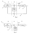
- Fig. 1 is a block diagram of a signal processing system constructed in accordance with one embodiment of the present invention
- Fig. 2 is a block diagram of another signal processing system constructed in accordance with the embodiment of Fig. 1 ;
- Fig. 3 is an operational diagram of a printing system being used in accordance with another embodiment of the present invention.
- Fig. 4 is a representational diagram of a portion of the system of Fig. 3 ;
- Figs. 5A and 5B are flow diagrams of alternative processes which may be used in the embodiment of Fig. 3 ;
- Fig. 6 is a representational diagram of an alternate version of the portion of Fig. 4 ;
- Fig. 7 is a representational diagram of a portion of the system of Fig. 3 ;
- Fig. 8 is a flow diagram of a printing control process, which covers a refinement of the present invention.
- Fig. 9 is a representational diagram of a printing system constructed for use in accordance with a refmement of the present invention.
- Fig. 10 is a representational diagram of a portion of the system of Fig. 9 .
- Fig. 1 is a block diagram of a signal processing circuit 10 constructed in accordance with one embodiment of the present invention.
- Circuit 10 includes image data conversion section 12, streak correction section 14 and a dithering section 16.
- Image data conversion section 12 receives image data through an input 18 and converts the data for each pixel to at least one energy value for use in energizing an individual heating element of a thermal print head array.
- the energy values represent the amount of time that each heating element is energized for each respective pixel.
- separate energy values are generated for the separate color components of each pixel. The present embodiment also adjusts those energy values in accordance with most recently printed pixels to compensate for residual heat build up in the print head array.
- Streak correction section 14 receives the energy values from conversion section 12 and a multiplier 20 multiplies each value by a respective streak profile correction factor, D n , for each respective heating element.
- D n streak profile correction factor
- the adjusted energy values resulting from the streak correction section 14 may not correspond directly to a limited set of energy states available in the printing process. Simply rounding the adjusted energy to the nearest available state may result in undesirable contouring artifacts in the printed image. Such artifacts will severely degrade the image quality when the number of available energy states is small.
- a process known as dithering is employed in section 16 to reduce the visibility of this contouring artifact.
- the process involves adding a predetermined pattern of noise 21 to the adjusted energy values. These noise signals are incorporated into the adjusted energy values by the adder 22.
- the repeating pattern spans adjacent heating elements as well as adjacent pixels printed by the same elements. The purpose is to bias the subsequent rounding introduced by the quantizer 24 either to the next higher or lower available energy state.
- the average of the quantized energy states over all the pixels in the repeating pattern more accurately represents the original adjusted energy.
- the human eye in observing the printed image at a normal viewing distance will perform a similar averaging and perceive a print density closer to the intended print density than would have been produced if the original adjusted energy was applied to the print head, thereby resulting in improved image quality.
- image data conversion section 12 includes a process for compensating for the thermal effects of an ongoing printing process.
- dithering section 16 includes a feedback path 26 which returns the actual printing energy values used to the conversion section 12, as a record of thermal history.
- D n respective correction factor
- a divider 28 can be used in conjunction with the corresponding respective correction factor to adjust the feedback values.
- a multiplier can be used with the corresponding inverse correction factor to produce the same result.
- Fig. 2 shows an alternate embodiment of the circuit 10 of Fig. 1 in the form of signal processing circuit 30, which includes image data conversion section 32, streak correction section 34 and dithering section 36.
- Circuit 30 reduces the amount of processing power and/or memory required from circuit 10 by substitution of a smaller feedback path 38. In this manner, the energy levels calculated for ideal heating elements are used for thermal compensation without the variation produced from either the streak correction adjustments or the dithering process.
- the embodiment shown in Fig. 2 is a very good approximation to the embodiment shown in Fig. 1 when the number of available energy states is large.
- Fig. 3 depicts another embodiment of the present invention, which covers a method for estimating the correction factors for the individual heating elements of a print head array for the purpose of reducing print density inconsistencies between individual heating elements and thereby reducing the appearance of streaks in the resulting printed material.
- This method is performed with a printer apparatus 40, generally shown to include a printing mechanism 42 and a control system 44 for controlling printer mechanism 42, along with a scanner 48.
- the method generally includes printing a sample 46 with printer mechanism 42 and measuring print densities from the sample 46 by means of scanner 48.
- Scanner 48 generally functions under the direction of control system 44 and print density data measured by scanner 48 is collected in control system 44.
- Control system 44 then takes the collected print density data and calculates a separate correction factor for each heating element for improving print density consistency between individual heating elements.
- the first calculated correction factors are then implemented by control system 44 into the printing operation of printer mechanism 42.
- the implemented first correction factors are then used in printer mechanism 42 for printing another sample 46, which is subsequently scanned by scanner 48 to measure the print densities produced with the use of the first correction factors.
- Control system 44 then takes the collected new density data and calculates an adjusted second set of correction factors for the individual heating elements.
- control system 44 implements the second set of correction factors into the printing operation of print mechanism 42 as multiplication products of individual second correction factors times their heating element respective first correction factors and substituting these second correction factor products in place of the first correction factors.
- Fig. 4 pictorially represents printer mechanism 42 including a print head array 50 having a multiplicity of adjacently located heating elements 52.
- Printer mechanism 42 is further shown with a printed sample 46, which has just been printed by print head array 50 by moving sample 46 in the direction of arrow 56.
- Print sample 46 generally includes a central portion 58 having a gradient of medium range print densities produced by substantially all of the heating elements 52.
- Central portion 58 shows a gradient between maximum and minimum print density, beginning and end portions 60, 62, respectively; however the preferred sample includes a gradient of medium range print densities located around the center of portion 58 to ensure that the print system's range of densities most sensitive to system variations causing streaking is adequately covered.
- print sample 46 such a range of densities is printed in the central portion 58.
- the print sample used to perform this analysis could also be of another form (such as a solid color field or a series of discrete steps in color density) providing that scanning and analysis of the density data yields a signal which is sufficiently strong to compensate for the streak-variation sought to be corrected.
- Print sample 46 further includes a multiplicity of fiducials or alignment marks 64, which are printed by specific heating elements within array 50.
- the print sample might start with mid-density flat field bars 64A to heat up the printing system enough so that the printing of the alignment marks 64 is ensured under all possible printing conditions.
- Alignment marks 64 are used by control system 44 for aligning the print density data with the corresponding heating elements and thereby identifying the individual row of pixels printed by each of the respective heating elements 52.
- the collected print density data corresponding to each individual heating element is determined in response to the alignment marks.
- the process may include the steps of aligning collected print density data in accordance with the alignment marks and determining sample pixels printed by individual heating elements.
- Fig. 5A shows process 65 that may be used for calculating the individual correction factors.
- the measured density in the print sample is denoted as d m,n , where the subscript n ( Fig. 4 ) denotes the heating element number of all of the heating elements which actually print sample 46, and the subscript m ( Fig. 4 ) denotes the print line number of the medium density lines within portion 58 ( Fig. 4 ).
- N denote the total number of heating elements 52 ( Fig. 4 ) printing the width of the print sample 46.
- the average line density d m across the heating elements for each line in the central portion 58 is calculated in step 65A.
- the deviation profile for the heating elements ⁇ d m,n in each line is calculated in step 65B by dividing the measured density by the average line density and subtracting one from the ratio. Alternatively, the deviation profile may also be computed by subtracting the average line density from the measured density as shown in step 65B.
- the average deviation profile ⁇ d n is calculated in step 65C by averaging the deviation profile across the lines in the central portion 58. In this step, a weighting function w m may be used for every line that may either reflect the contribution of that line to the streak sensitivity of the printing system, or the streak visibility.
- correction factor D n is calculated using the equation shown in 65D.
- the factor f may be experimentally selected to provide the greatest print density consistency between heating elements, dependent upon the specific print head array application. In one embodiment, values closest to 0.6 were found to achieve best results in combination with multiple iterations of the sequence depicted in Fig. 3 .
- Fig. 5B shows an alternative process 66 for calculating the density correction factors.
- the measured densities are weighted and averaged across the lines in step 66A to produce an average density d n for each heating element n .
- a global average is calculated in step 66B by averaging all d n .
- An average deviation profile is calculated in step 66C by dividing the average density d n for each heating element by the global average density and subtracting one from the ratio.
- the average deviation profile may also be computed by subtracting the global average density from the average density d n for each heating element as shown in step 66C.
- the convection factors are obtained in step 66D using the same equation as in the embodiment shown in Fig. 5A .
- Fig. 6 shows the printing of an alternate sample 70, which may be used for purposes of the present invention.
- Fig. 6 also pictorially includes a print head array 72 shown in combination with a roller 74, which biases the print media of sample 70 against print head array 72.
- Roller 74 includes a pressure surface 76 that has a certain circumference 78.
- a central portion 80 is printed having a consistent medium density.
- the print density data collected for individual heating elements of array 72 may be averaged over the length 78a of the circumference 78, to thereby average out inconsistencies which appear in the pressure surface 76 of roller 74.
- the individual correction factors are then calculated as described in reference to Fig. 5A-B .
- Fig.7 pictorially shows a print head 100 being used to print on a print medium 102 to explain refinements of the process described herein to further improve print density consistency between heating elements.
- Print head 100 includes an array 104 of heating elements (shown in phantom), which extends between opposing ends 100a, 100b of print head 100.
- Array 104 also extends beyond opposing edges 102a, 102b of print medium 102.
- a further correction technique is also depicted in Fig. 7 for heating elements that extend beyond the opposing edges 102a, 102b of print medium 102, as exemplified by region 108. Because the heating elements are not in contact with print media and the heat normally used for printing is not dissipated into print medium, this heat builds up faster than heat in the central portion of array 104. This built up heat can migrate to heating elements in contact with print medium 102 and cause higher than desired print densities. To help alleviate this heat build up, the energy values used for heating elements located beyond print medium edge 102b in region 108, are increasingly reduced for heating elements located further from edge 102b and towards print head end 100b. This reduction in the correction factors may also be extended slightly inwards from the edge 102b towards print head end 100a since in the actual printing the exact location of edge 102b may vary from print to print.
- Fig 8 is a flow chart of a process 110 representing yet another refinement of the present invention.
- Process 110 deals with the long term operation of a printing apparatus and begins with step 112 of determining a print density correction factor for each heating element as described in reference to Figs 3-5 .
- step 114 includes initially measuring the resistance of each heating element of the array in a known manner. These initial measurements are stored in step 116 for future reference.
- Process 110 then allows normal operation of the printer apparatus and measures that operation in step 118. Any suitable aspect of measurements may be used, including the number of prints, hours of operation, etc.
- step 120 makes a subsequent measurement of each heating element resistance, for the reason that resistances can change with usage.
- Step 122 uses the stored initially measured resistance values and the subsequently measured resistance values to adjust the individual correction factors in response to the respective resistance changes.
- the adjustment is accomplished in step 124 which includes multiplying the current correction factor, D n , for each heating element by the ratio of the respective subsequently measured resistance value, R s , to the respective initially measured resistance value R i .
- step 122 may be done automatically, or it may be contingent upon a sufficient change in each resistance value. Further, the subsequently measured values may also be stored in step 126 for making further correction factor adjustments after further printer usage has occurred.
- FIGs. 9 and 10 depict a further refinement of the present invention, which embodiment covers a method for controlling individual heating elements of a print head array for the purpose of reducing print density inconsistencies between individual heating elements and thereby reducing the appearance of streaks in the resulting printed material.
- a printer apparatus 127 generally includes a printing mechanism 129 with an embedded scanning capability and a control system 128 for controlling printer mechanism 129 and that embedded scanning capability.
- Fig. 10 depicts printing apparatus 129 and the position of a scanning head 132 located after the printing elements 131 along the general direction of motion 134 of print medium 133.
- the method generally includes printing a streak correction sample on medium 133 with printer elements 131 and immediately measuring print densities from the sample by means of embedded scanning head 132. Scanning head 132 functions under the direction of control system 128 and print density data measured by scanning head 132 is collected in control system 128. In this embodiment, analysis and subsequent corrections are performed as described in the previous embodiments.
- correction factors may be recalculated periodically without requiring the presence of a service technician.
- the general steps of printing a streak correction sample, measuring the print density and calculating new print density correction factors may be periodically performed over long term operation of printer apparatus 127 and used as a monitor for significant and sudden changes in correction factors and performance, which could indicate other performance issues or even trigger servicing of the apparatus.
- the measured print density data could be uploaded via an internet or other suitable process, to allow remote inspection and analysis.
- multiplier print density correction factors enhances the compatibility of the print density correction function with the print head thermal correction function and the dithering function, thus enhancing the combined performance of these functions.
- multiplier correction factors are also readily adjusted over long term printing operations in response to heating element resistance changes without affecting or requiring recalibration of any other part of the control process.
- the use of an inexpensive scanner in the calibration process allows the present invention to be used for remote printing systems such as publicly available printing kiosks that allow anyone to do their own photo finishing of digital or printed images.
- Such kiosks often contain a suitable scanner to allow periodic recalibration by a service technician, or a simple scanner can be brought to the system by the technician.
- the computing power used in such kiosks is more than sufficient to run the required software.
- the printed samples may be sent to a separate location by any suitable means for independent analysis and calculation of correction factors, which then might be downloaded back to the kiosk.
- incorporating a scanning head in the printing apparatus increases the amount of remote monitoring and maintenance that can be performed.
Landscapes
- Electronic Switches (AREA)
Claims (18)
- Verfahren zur Steuerung der Druckdichte von einzelnen Heizelementen (52) einer thermischen Druckkopfanordnung (50), die Schritte umfassend:- Bestimmen jeweiliger Energiewerte für jedes Heizelement (52) einer thermischen Druckkopfanordnung (50) im Ansprechen auf zu druckende Bildpixeldaten;- Anpassen bestimmter Energiewerte entsprechend jedem jeweiligen Heizelement (52) im Ansprechen auf Restwärmeeffekte aus zuletzt gedruckten Bildpixeln;- Multiplizieren angepasster Energiewerte, die dem Schritt des Anpassens entstammen, mit einem jeweiligen vorbestimmten Korrekturfaktor für ein oder mehrere jeweilige Heizelemente (52) zur Verbesserung der Druckdichtekonsistenz zwischen einzelnen Heizelementen (52); und- Dithern angepasster Energiewerte, die dem Schritt des Multiplizierens entstammen, abhängig von benachbarten Bildpixeln.
- Verfahren nach Anspruch 1, wobei die Korrekturfaktoren jeweils eine Abweichung einer Druckdichte eines jeweiligen Heizelements (52) von einer mittleren Druckdichte darstellen.
- Verfahren nach Anspruch 1, wobei der Schritt des Anpassens einen Schritt der Bestimmung von Restwärmeeffekten für jedes Heizelement (52) aus jeweiligen geditherten Energiewerten umfasst, die dem Schritt des Ditherns entstammen.
- Verfahren nach Anspruch 3, wobei der Schritt der Bestimmung von Restwärmeeffekten umfasst, aus dem geditherten Energiewert jedes Bildpixels den jeweiligen Korrekturfaktor herauszurechnen.
- Verfahren nach Anspruch 1, wobei der Schritt des Multiplizierens einen Änderungsbetrag der angepassten Energiewerte hervorbringt, der proportional zu jedem angepassten Energiewert ist.
- Verfahren nach Anspruch 1, darüber hinaus einen Prozess zur Bestimmung eines Korrekturfaktors für jedes Heizelement (52) umfassend, der folgende Schritte umfasst:- Drucken eines Musters mit einer Druckkopfanordnung (50);- Messen von Druckdichten aus dem Muster; und- Berechnen von Korrekturfaktoren für jeweilige einzelne Heizelemente (52) aus den gemessenen Druckdichten, wobei die Korrekturfaktoren jeweils eine Abweichung der Druckdichte eines jeweiligen Heizelements (52) von einer mittleren Druckdichte darstellen.
- Verfahren nach Anspruch 6, wobei der Schritt des Messens umfasst, das Muster zu scannen, um Druckdichtedaten zu sammeln.
- Verfahren nach Anspruch 7, wobei das gedruckte Muster in dem Muster gedruckte Ausrichtmarkierungen umfasst, und wobei darüber hinaus der Schritt des Messens den Schritt der Bestimmung der gesammelten Daten entsprechend jedem einzelnen Heizelement (52) im Ansprechen auf die Ausrichtmarkierungen umfasst.
- Verfahren nach Anspruch 6, darüber hinaus umfassend, die Schritte des Druckens, Messens und Berechnens periodisch zu wiederholen, um signifikante Änderungen der Korrekturfaktoren und dadurch der Druckdichtekonsistenz der Heizelemente (52) während eines Langzeitbetriebs der Druckkopfanordnung (50) festzustellen.
- Verfahren nach Anspruch 1, darüber hinaus folgende Schritte umfassend:- anfängliches Messen jeweiliger Widerstandswerte für jedes Heizelement (52);- Speichern dieser anfänglich gemessenen Widerstandswerte für zukünftige Bezugnahme;- späteres Messen jeweiliger Widerstandswerte für die Heizelemente (52) nach einer gewissen Einsatzdauer der Druckkopfanordnung (50); und- Bestimmen jeweiliger angepasster Korrekturfaktoren für ein oder mehrere Heizelemente (52) im Ansprechen auf Veränderungen der jeweiligen Widerstandswerte einzelner Heizelemente (52) zwischen dem Schritt des anfänglichen Messens und dem Schritt des späteren Messens.
- Verfahren nach Anspruch 10, wobei der Schritt des Bestimmens jeweiliger angepasster Korrekturfaktoren umfasst, Korrekturfaktoren, die für jeweilige einzelne Heizelemente (52) während des Schritts des anfänglichen Messens verwendet werden, mit einem Verhältnis eines jeweiligen später gemessenen Widerstandswerts zu einem jeweiligen anfänglich gemessenen Widerstandswert zu multiplizieren.
- Druckvorrichtung mit einer thermischen Druckkopfanordnung (50) aus Heizelementen (52), wobei die Vorrichtung ein Steuerungssystem umfasst mit:- einer Einrichtung zur Bestimmung von Energiewerten für jedes Heizelement (52) einer Druckkopfanordnung (50) im Ansprechen auf empfangene Bildpixeldaten;- einer Einrichtung zur Anpassung bestimmter Energiewerte gemäß jedem jeweiligen Heizelement (52) im Ansprechen auf Restwärmeeffekte aus zuletzt gedruckten Bildpixeln;- einer Einrichtung zum Korrigieren angepasster Energiewerte in Bezug auf jedes Heizelement (52) durch Multiplizieren der angepassten Energiewerte mit einem jeweiligen vorbestimmten Korrekturfaktor zur Verbesserung der Druckdichtekonsistenz zwischen einzelnen Heizelementen (52); und- einer Einrichtung zum Dithern angepasster Energiewerte, die dem Prozess zum Multiplizieren entstammen, abhängig von benachbarten Bildpixeln.
- Vorrichtung nach Anspruch 12, wobei die Einrichtung zum Korrigieren eine Einrichtung zum Multiplizieren angepasster Energiewerte mit jeweiligen vorbestimmten Korrekturfaktoren für ein oder mehrere jeweilige-Heizelemente (52) umfasst.
- Vorrichtung nach Anspruch 12, wobei die Einrichtung zur Anpassung eine Einrichtung zur Bestimmung von Restwärmeeffekten für jedes Heizelement (52) aus jeweiligen geditherten Energiewerten umfasst, die dem Dither-Prozess entstammen.
- Vorrichtung nach Anspruch 12, darüber hinaus umfassend:- eine Einrichtung zur anfänglichen Messung jeweiliger Widerstandswerte für jedes Heizelement (52) und zum Speichern dieser anfänglich gemessenen Widerstandswerte für zukünftige Bezugnahme;- eine Einrichtung zur späteren Messung jeweiliger Widerstandswerte für die Heizelemente (52) nach einer gewissen Einsatzdauer der Druckkopfanordnung (50); und- eine Einrichtung zur Bestimmung jeweiliger angepasster Korrekturfaktoren für ein oder mehrere Heizelemente (52) im Ansprechen auf Veränderungen der jeweiligen Widerstandswerte einzelner Heizelemente (52) zwischen dem Prozess der anfänglichen Messung und dem Prozess der späteren Messung.
- Vorrichtung nach Anspruch 15, wobei die Einrichtung zur Bestimmung jeweiliger angepasster Korrekturfaktoren eine Einrichtung umfasst, um einen aktuellen Korrekturfaktor eines einzelnen Heizelements (52) mit einem Verhältnis eines jeweiligen später gemessenen Widerstandswertes zu einem jeweiligen anfänglich gemessenen Widerstandswert zu multiplizieren.
- Vorrichtung nach Anspruch 12, darüber hinaus eine Einrichtung zur Bestimmung eines Korrekturfaktors für jedes Heizelementen (52) umfassend, einschließlich folgender Prozessschritte:- Drucken eines Musters mit einer Druckkopfanordnung (50);- Messen von Druckdichten aus dem Muster; und- Berechnen von Korrekturfaktoren für jeweilige einzelne Heizelemente (52) aus den gemessenen Druckdichten, wobei die Korrekturfaktoren jeweils eine Abweichung der Druckdichte eines jeweiligen Heizelements (52) von einer mittleren Druckdichte darstellen.
- Vorrichtung nach Anspruch 17, darüber hinaus eine Einrichtung zur periodischen Wiederholung der Prozessschritte des Druckens, Messens und Berechnens umfassend, um signifikante Änderungen der Korrekturfaktoren und dadurch der Druckdichtekonsistenz der Heizelemente (52) während eines Langzeitbetriebs der Druckkopfanordnung (50) festzustellen.
Applications Claiming Priority (2)
| Application Number | Priority Date | Filing Date | Title |
|---|---|---|---|
| US10/990,672 US7369145B2 (en) | 2005-01-10 | 2005-01-10 | Method and apparatus for controlling the uniformity of print density of a thermal print head array |
| PCT/US2005/046717 WO2006076146A2 (en) | 2005-01-10 | 2005-12-21 | Method and apparatus for controlling the uniformity of print density of a thermal print head array |
Publications (2)
| Publication Number | Publication Date |
|---|---|
| EP1846246A2 EP1846246A2 (de) | 2007-10-24 |
| EP1846246B1 true EP1846246B1 (de) | 2012-02-08 |
Family
ID=36652823
Family Applications (1)
| Application Number | Title | Priority Date | Filing Date |
|---|---|---|---|
| EP05855300A Expired - Lifetime EP1846246B1 (de) | 2005-01-10 | 2005-12-21 | Verfahren und vorrichtung zur steuerung der gleichförmigkeit der druckdichte einer thermodruckkopfanordnung |
Country Status (4)
| Country | Link |
|---|---|
| US (2) | US7369145B2 (de) |
| EP (1) | EP1846246B1 (de) |
| AT (1) | ATE544602T1 (de) |
| WO (1) | WO2006076146A2 (de) |
Families Citing this family (16)
| Publication number | Priority date | Publication date | Assignee | Title |
|---|---|---|---|---|
| US7791626B2 (en) * | 2001-05-30 | 2010-09-07 | Zink Imaging, Inc. | Print head pulsing techniques for multicolor printers |
| US7830405B2 (en) | 2005-06-23 | 2010-11-09 | Zink Imaging, Inc. | Print head pulsing techniques for multicolor printers |
| US7388686B2 (en) * | 2003-02-25 | 2008-06-17 | Zink Imaging, Llc | Image stitching for a multi-head printer |
| CA2446880C (en) * | 2001-05-30 | 2010-08-03 | Polaroid Corporation | Thermal imaging system |
| US8377844B2 (en) * | 2001-05-30 | 2013-02-19 | Zink Imaging, Inc. | Thermally-insulating layers and direct thermal imaging members containing same |
| US7369145B2 (en) * | 2005-01-10 | 2008-05-06 | Polaroid Corporation | Method and apparatus for controlling the uniformity of print density of a thermal print head array |
| US8759818B2 (en) | 2009-02-27 | 2014-06-24 | E I Du Pont De Nemours And Company | Deuterated compounds for electronic applications |
| WO2010114583A1 (en) | 2009-04-03 | 2010-10-07 | E. I. Du Pont De Nemours And Company | Electroactive materials |
| WO2011040939A1 (en) | 2009-09-29 | 2011-04-07 | E. I. Du Pont De Nemours And Company | Deuterated compounds for luminescent applications |
| CN103862891B (zh) | 2012-12-17 | 2016-08-03 | 山东新北洋信息技术股份有限公司 | 打印机的控制方法及打印机 |
| JP5996469B2 (ja) * | 2013-03-28 | 2016-09-21 | シチズンホールディングス株式会社 | プリンタ |
| JP6164476B2 (ja) * | 2013-07-25 | 2017-07-19 | ブラザー工業株式会社 | 印刷装置 |
| US10399359B2 (en) | 2017-09-06 | 2019-09-03 | Vocollect, Inc. | Autocorrection for uneven print pressure on print media |
| CN111361294B (zh) * | 2020-03-30 | 2021-08-06 | 厦门汉印电子技术有限公司 | 打印头分辨率的识别方法、装置、打印机及存储介质 |
| CN114506159B (zh) * | 2021-12-27 | 2023-05-16 | 珠海智汇网络设备有限公司 | 双色打印驱动方法、热敏打印机和计算机可读存储介质 |
| CN119974780B (zh) * | 2025-01-17 | 2026-03-20 | 武汉精臣智慧标识科技有限公司 | 热敏打印机的加热控制方法、装置以及电子设备 |
Citations (1)
| Publication number | Priority date | Publication date | Assignee | Title |
|---|---|---|---|---|
| EP0304916A1 (de) * | 1987-08-28 | 1989-03-01 | Nec Corporation | Steuerschaltung für thermisches Drucken |
Family Cites Families (19)
| Publication number | Priority date | Publication date | Assignee | Title |
|---|---|---|---|---|
| US4647184A (en) | 1985-03-18 | 1987-03-03 | Xerox Corporation | Automatic setup apparatus for an electrophotographic printing machine |
| US4758966A (en) | 1986-05-05 | 1988-07-19 | Ncr Canada Ltd. - Ncr Canada Ltee | Thermal printing apparatus and method |
| US4827279A (en) | 1988-06-16 | 1989-05-02 | Eastman Kodak Company | Process for correcting across-the-head nonuniformity in thermal printers |
| JP2516068B2 (ja) | 1989-04-28 | 1996-07-10 | 日本ビクター株式会社 | サ―マルヘッドの蓄熱補正回路 |
| GB9007014D0 (en) | 1990-03-29 | 1990-05-30 | Dowty Maritime Systems Ltd | Thermal recording apparatus |
| US5149960B1 (en) | 1991-07-03 | 1994-08-30 | Donnelly R R & Sons | Method of converting scanner signals into colorimetric signals |
| JP2785547B2 (ja) | 1991-10-15 | 1998-08-13 | 富士ゼロックス株式会社 | 用紙サイズ検出装置 |
| JP2993804B2 (ja) | 1992-09-01 | 1999-12-27 | 富士写真フイルム株式会社 | サーマルヘッドの抵抗値測定方法及び装置並びにこれを備えたサーマルプリンタ |
| DE69419072T2 (de) * | 1993-05-28 | 2000-02-17 | Agfa-Gevaert N.V., Mortsel | Verfahren zum Korrigieren der Ungleichmässigkeit in einem Thermodrucksystem |
| US5608333A (en) | 1993-06-18 | 1997-03-04 | Fuji Photo Film Co., Ltd. | Method of driving heating element to match its resistance, thermal printer, and resistance measuring device |
| US6116714A (en) | 1994-03-04 | 2000-09-12 | Canon Kabushiki Kaisha | Printing head, printing method and apparatus using same, and apparatus and method for correcting said printing head |
| US5608442A (en) | 1994-08-31 | 1997-03-04 | Lasermaster Corporation | Heating control for thermal printers |
| JP3590702B2 (ja) | 1995-11-16 | 2004-11-17 | 富士写真フイルム株式会社 | サーマルヘッドの抵抗データ測定方法及び装置並びにこれを備えたサーマルプリンタ |
| US6283650B1 (en) | 1997-07-28 | 2001-09-04 | Canon Kabushiki Kaisha | Printing device having an output level compensation function |
| EP0925925A3 (de) | 1997-12-26 | 2000-01-19 | Canon Kabushiki Kaisha | Verfahren zum Korrigieren eines Aufzeichnungskopfes, Korrigiervorrichtung dazu, mit dieser Vorrichtung korrigierter Aufzeichnungskopf und diesen Aufzeichnungskopf verwendende Aufzeichnungsvorrichtung |
| US6584233B1 (en) | 1999-07-19 | 2003-06-24 | Eastman Kodak Company | Method for determining the components of image noise patterns of an imaging device and use of this method in an imaging device |
| GB2356375B (en) | 1999-11-22 | 2003-04-09 | Esselte Nv | A method of controlling a print head |
| US6554388B1 (en) | 2001-10-15 | 2003-04-29 | Eastman Kodak Company | Method for improving printer uniformity |
| US7369145B2 (en) * | 2005-01-10 | 2008-05-06 | Polaroid Corporation | Method and apparatus for controlling the uniformity of print density of a thermal print head array |
-
2005
- 2005-01-10 US US10/990,672 patent/US7369145B2/en not_active Expired - Fee Related
- 2005-12-21 WO PCT/US2005/046717 patent/WO2006076146A2/en not_active Ceased
- 2005-12-21 AT AT05855300T patent/ATE544602T1/de active
- 2005-12-21 EP EP05855300A patent/EP1846246B1/de not_active Expired - Lifetime
-
2007
- 2007-10-04 US US11/906,830 patent/US7545401B2/en not_active Expired - Fee Related
Patent Citations (1)
| Publication number | Priority date | Publication date | Assignee | Title |
|---|---|---|---|---|
| EP0304916A1 (de) * | 1987-08-28 | 1989-03-01 | Nec Corporation | Steuerschaltung für thermisches Drucken |
Also Published As
| Publication number | Publication date |
|---|---|
| WO2006076146A3 (en) | 2007-03-08 |
| US20080030567A1 (en) | 2008-02-07 |
| WO2006076146A2 (en) | 2006-07-20 |
| EP1846246A2 (de) | 2007-10-24 |
| ATE544602T1 (de) | 2012-02-15 |
| US7545401B2 (en) | 2009-06-09 |
| US7369145B2 (en) | 2008-05-06 |
| US20060152573A1 (en) | 2006-07-13 |
Similar Documents
| Publication | Publication Date | Title |
|---|---|---|
| US7545401B2 (en) | Method and apparatus for controlling the uniformity of print density of a thermal print head array | |
| EP0346647B1 (de) | Verfahren zum Korrigieren der Ungleichmässigkeit entlang des Kopfes von Wärmedruckern | |
| US7038816B2 (en) | Macro uniformity correction for x-y separable non-uniform | |
| EP1267217B1 (de) | Eichung eines Mehrfarbenbilderzeugungssystems unter Verwendung von vorhergesagter Farbverschiebung | |
| US7424169B2 (en) | Active compensation of streaks using spatial filtering and feedback control | |
| US6554388B1 (en) | Method for improving printer uniformity | |
| US6318260B1 (en) | Ink key control in a printing press including lateral ink spread, ink saturation, and back-flow compensation | |
| EP2296902B1 (de) | System zur korrektur der thermischen reaktion für mehrfarbendruck | |
| US7724406B2 (en) | Halftone independent color drift correction | |
| JP2581509B2 (ja) | 感熱プリンタシステムおよびこれに使用する方法 | |
| US5800075A (en) | Data processing method for eliminating influence of heat accumulating in thermal head | |
| US6603499B2 (en) | Printhead having non-uniformity correction based on spatial energy profile data, a method for non-uniformity correction of a printhead, and an apparatus for measuring spatial energy profile data in a printhead | |
| US4827281A (en) | Process for correcting down-the-page nonuniformity in thermal printing | |
| US7446789B2 (en) | Heat accumulation correcting method, thermal printer, and computer-executable program | |
| US6108019A (en) | Thermal printing method for preventing degrading of print quality due to fluctuation in transport speed of recording sheet | |
| US7375740B2 (en) | Method and apparatus for adjusting printbar uniformity | |
| US20010031165A1 (en) | Data processing method for eliminating influence of heat accumulation in thermal head of thermal printer | |
| EP0947334B1 (de) | Bilderzeugungsverfahren für einen thermischen Übertragungsdrucker | |
| US10583665B2 (en) | Printing apparatus, printing method, and storage medium | |
| EP3957484A1 (de) | Verminderung der streifigkeit beim tintenstrahldruck | |
| US7570393B2 (en) | Method for calibration of a printer | |
| US10675886B2 (en) | Printing apparatus, printing method, and storage medium | |
| US20230186043A1 (en) | Determining color responses | |
| Wu | Fast printer color calibration using pre-build linearization tables | |
| JPH07314758A (ja) | サーマルヘッド駆動制御方法及び装置 |
Legal Events
| Date | Code | Title | Description |
|---|---|---|---|
| PUAI | Public reference made under article 153(3) epc to a published international application that has entered the european phase |
Free format text: ORIGINAL CODE: 0009012 |
|
| 17P | Request for examination filed |
Effective date: 20070723 |
|
| AK | Designated contracting states |
Kind code of ref document: A2 Designated state(s): AT BE BG CH CY CZ DE DK EE ES FI FR GB GR HU IE IS IT LI LT LU LV MC NL PL PT RO SE SI SK TR |
|
| 17Q | First examination report despatched |
Effective date: 20071112 |
|
| DAX | Request for extension of the european patent (deleted) | ||
| RAP1 | Party data changed (applicant data changed or rights of an application transferred) |
Owner name: PLR IP HOLDINGS, LLC |
|
| RAP1 | Party data changed (applicant data changed or rights of an application transferred) |
Owner name: MITCHAM GLOBAL INVESTMENTS LTD. |
|
| GRAP | Despatch of communication of intention to grant a patent |
Free format text: ORIGINAL CODE: EPIDOSNIGR1 |
|
| GRAS | Grant fee paid |
Free format text: ORIGINAL CODE: EPIDOSNIGR3 |
|
| GRAA | (expected) grant |
Free format text: ORIGINAL CODE: 0009210 |
|
| AK | Designated contracting states |
Kind code of ref document: B1 Designated state(s): AT BE BG CH CY CZ DE DK EE ES FI FR GB GR HU IE IS IT LI LT LU LV MC NL PL PT RO SE SI SK TR |
|
| REG | Reference to a national code |
Ref country code: GB Ref legal event code: FG4D |
|
| REG | Reference to a national code |
Ref country code: AT Ref legal event code: REF Ref document number: 544602 Country of ref document: AT Kind code of ref document: T Effective date: 20120215 Ref country code: CH Ref legal event code: EP |
|
| REG | Reference to a national code |
Ref country code: DE Ref legal event code: R096 Ref document number: 602005032637 Country of ref document: DE Effective date: 20120329 |
|
| REG | Reference to a national code |
Ref country code: NL Ref legal event code: VDEP Effective date: 20120208 |
|
| LTIE | Lt: invalidation of european patent or patent extension |
Effective date: 20120208 |
|
| PG25 | Lapsed in a contracting state [announced via postgrant information from national office to epo] |
Ref country code: NL Free format text: LAPSE BECAUSE OF FAILURE TO SUBMIT A TRANSLATION OF THE DESCRIPTION OR TO PAY THE FEE WITHIN THE PRESCRIBED TIME-LIMIT Effective date: 20120208 Ref country code: LT Free format text: LAPSE BECAUSE OF FAILURE TO SUBMIT A TRANSLATION OF THE DESCRIPTION OR TO PAY THE FEE WITHIN THE PRESCRIBED TIME-LIMIT Effective date: 20120208 Ref country code: IS Free format text: LAPSE BECAUSE OF FAILURE TO SUBMIT A TRANSLATION OF THE DESCRIPTION OR TO PAY THE FEE WITHIN THE PRESCRIBED TIME-LIMIT Effective date: 20120608 |
|
| PG25 | Lapsed in a contracting state [announced via postgrant information from national office to epo] |
Ref country code: PL Free format text: LAPSE BECAUSE OF FAILURE TO SUBMIT A TRANSLATION OF THE DESCRIPTION OR TO PAY THE FEE WITHIN THE PRESCRIBED TIME-LIMIT Effective date: 20120208 Ref country code: GR Free format text: LAPSE BECAUSE OF FAILURE TO SUBMIT A TRANSLATION OF THE DESCRIPTION OR TO PAY THE FEE WITHIN THE PRESCRIBED TIME-LIMIT Effective date: 20120509 Ref country code: LV Free format text: LAPSE BECAUSE OF FAILURE TO SUBMIT A TRANSLATION OF THE DESCRIPTION OR TO PAY THE FEE WITHIN THE PRESCRIBED TIME-LIMIT Effective date: 20120208 Ref country code: PT Free format text: LAPSE BECAUSE OF FAILURE TO SUBMIT A TRANSLATION OF THE DESCRIPTION OR TO PAY THE FEE WITHIN THE PRESCRIBED TIME-LIMIT Effective date: 20120608 Ref country code: FI Free format text: LAPSE BECAUSE OF FAILURE TO SUBMIT A TRANSLATION OF THE DESCRIPTION OR TO PAY THE FEE WITHIN THE PRESCRIBED TIME-LIMIT Effective date: 20120208 Ref country code: BE Free format text: LAPSE BECAUSE OF FAILURE TO SUBMIT A TRANSLATION OF THE DESCRIPTION OR TO PAY THE FEE WITHIN THE PRESCRIBED TIME-LIMIT Effective date: 20120208 |
|
| REG | Reference to a national code |
Ref country code: AT Ref legal event code: MK05 Ref document number: 544602 Country of ref document: AT Kind code of ref document: T Effective date: 20120208 |
|
| PG25 | Lapsed in a contracting state [announced via postgrant information from national office to epo] |
Ref country code: CY Free format text: LAPSE BECAUSE OF FAILURE TO SUBMIT A TRANSLATION OF THE DESCRIPTION OR TO PAY THE FEE WITHIN THE PRESCRIBED TIME-LIMIT Effective date: 20120208 |
|
| PG25 | Lapsed in a contracting state [announced via postgrant information from national office to epo] |
Ref country code: CZ Free format text: LAPSE BECAUSE OF FAILURE TO SUBMIT A TRANSLATION OF THE DESCRIPTION OR TO PAY THE FEE WITHIN THE PRESCRIBED TIME-LIMIT Effective date: 20120208 Ref country code: SI Free format text: LAPSE BECAUSE OF FAILURE TO SUBMIT A TRANSLATION OF THE DESCRIPTION OR TO PAY THE FEE WITHIN THE PRESCRIBED TIME-LIMIT Effective date: 20120208 Ref country code: RO Free format text: LAPSE BECAUSE OF FAILURE TO SUBMIT A TRANSLATION OF THE DESCRIPTION OR TO PAY THE FEE WITHIN THE PRESCRIBED TIME-LIMIT Effective date: 20120208 Ref country code: EE Free format text: LAPSE BECAUSE OF FAILURE TO SUBMIT A TRANSLATION OF THE DESCRIPTION OR TO PAY THE FEE WITHIN THE PRESCRIBED TIME-LIMIT Effective date: 20120208 Ref country code: SE Free format text: LAPSE BECAUSE OF FAILURE TO SUBMIT A TRANSLATION OF THE DESCRIPTION OR TO PAY THE FEE WITHIN THE PRESCRIBED TIME-LIMIT Effective date: 20120208 Ref country code: DK Free format text: LAPSE BECAUSE OF FAILURE TO SUBMIT A TRANSLATION OF THE DESCRIPTION OR TO PAY THE FEE WITHIN THE PRESCRIBED TIME-LIMIT Effective date: 20120208 |
|
| PG25 | Lapsed in a contracting state [announced via postgrant information from national office to epo] |
Ref country code: IT Free format text: LAPSE BECAUSE OF FAILURE TO SUBMIT A TRANSLATION OF THE DESCRIPTION OR TO PAY THE FEE WITHIN THE PRESCRIBED TIME-LIMIT Effective date: 20120208 Ref country code: SK Free format text: LAPSE BECAUSE OF FAILURE TO SUBMIT A TRANSLATION OF THE DESCRIPTION OR TO PAY THE FEE WITHIN THE PRESCRIBED TIME-LIMIT Effective date: 20120208 |
|
| PLBE | No opposition filed within time limit |
Free format text: ORIGINAL CODE: 0009261 |
|
| STAA | Information on the status of an ep patent application or granted ep patent |
Free format text: STATUS: NO OPPOSITION FILED WITHIN TIME LIMIT |
|
| 26N | No opposition filed |
Effective date: 20121109 |
|
| PG25 | Lapsed in a contracting state [announced via postgrant information from national office to epo] |
Ref country code: AT Free format text: LAPSE BECAUSE OF FAILURE TO SUBMIT A TRANSLATION OF THE DESCRIPTION OR TO PAY THE FEE WITHIN THE PRESCRIBED TIME-LIMIT Effective date: 20120208 |
|
| REG | Reference to a national code |
Ref country code: DE Ref legal event code: R097 Ref document number: 602005032637 Country of ref document: DE Effective date: 20121109 |
|
| PG25 | Lapsed in a contracting state [announced via postgrant information from national office to epo] |
Ref country code: ES Free format text: LAPSE BECAUSE OF FAILURE TO SUBMIT A TRANSLATION OF THE DESCRIPTION OR TO PAY THE FEE WITHIN THE PRESCRIBED TIME-LIMIT Effective date: 20120519 |
|
| PG25 | Lapsed in a contracting state [announced via postgrant information from national office to epo] |
Ref country code: BG Free format text: LAPSE BECAUSE OF FAILURE TO SUBMIT A TRANSLATION OF THE DESCRIPTION OR TO PAY THE FEE WITHIN THE PRESCRIBED TIME-LIMIT Effective date: 20120508 Ref country code: MC Free format text: LAPSE BECAUSE OF NON-PAYMENT OF DUE FEES Effective date: 20121231 |
|
| REG | Reference to a national code |
Ref country code: CH Ref legal event code: PL |
|
| REG | Reference to a national code |
Ref country code: IE Ref legal event code: MM4A |
|
| PG25 | Lapsed in a contracting state [announced via postgrant information from national office to epo] |
Ref country code: CH Free format text: LAPSE BECAUSE OF NON-PAYMENT OF DUE FEES Effective date: 20121231 Ref country code: LI Free format text: LAPSE BECAUSE OF NON-PAYMENT OF DUE FEES Effective date: 20121231 Ref country code: IE Free format text: LAPSE BECAUSE OF NON-PAYMENT OF DUE FEES Effective date: 20121221 |
|
| PGFP | Annual fee paid to national office [announced via postgrant information from national office to epo] |
Ref country code: GB Payment date: 20131227 Year of fee payment: 9 |
|
| PGFP | Annual fee paid to national office [announced via postgrant information from national office to epo] |
Ref country code: FR Payment date: 20131217 Year of fee payment: 9 |
|
| PG25 | Lapsed in a contracting state [announced via postgrant information from national office to epo] |
Ref country code: TR Free format text: LAPSE BECAUSE OF FAILURE TO SUBMIT A TRANSLATION OF THE DESCRIPTION OR TO PAY THE FEE WITHIN THE PRESCRIBED TIME-LIMIT Effective date: 20120208 |
|
| PG25 | Lapsed in a contracting state [announced via postgrant information from national office to epo] |
Ref country code: LU Free format text: LAPSE BECAUSE OF NON-PAYMENT OF DUE FEES Effective date: 20121221 |
|
| PG25 | Lapsed in a contracting state [announced via postgrant information from national office to epo] |
Ref country code: HU Free format text: LAPSE BECAUSE OF FAILURE TO SUBMIT A TRANSLATION OF THE DESCRIPTION OR TO PAY THE FEE WITHIN THE PRESCRIBED TIME-LIMIT Effective date: 20051221 |
|
| GBPC | Gb: european patent ceased through non-payment of renewal fee |
Effective date: 20141221 |
|
| REG | Reference to a national code |
Ref country code: FR Ref legal event code: ST Effective date: 20150831 |
|
| PG25 | Lapsed in a contracting state [announced via postgrant information from national office to epo] |
Ref country code: GB Free format text: LAPSE BECAUSE OF NON-PAYMENT OF DUE FEES Effective date: 20141221 |
|
| PG25 | Lapsed in a contracting state [announced via postgrant information from national office to epo] |
Ref country code: FR Free format text: LAPSE BECAUSE OF NON-PAYMENT OF DUE FEES Effective date: 20141231 |
|
| PGFP | Annual fee paid to national office [announced via postgrant information from national office to epo] |
Ref country code: DE Payment date: 20151229 Year of fee payment: 11 |
|
| REG | Reference to a national code |
Ref country code: DE Ref legal event code: R119 Ref document number: 602005032637 Country of ref document: DE |
|
| PG25 | Lapsed in a contracting state [announced via postgrant information from national office to epo] |
Ref country code: DE Free format text: LAPSE BECAUSE OF NON-PAYMENT OF DUE FEES Effective date: 20170701 |