EP1847397A2 - Vorrichtung und Verfahren zum Bedrucken von Wellpappe - Google Patents
Vorrichtung und Verfahren zum Bedrucken von Wellpappe Download PDFInfo
- Publication number
- EP1847397A2 EP1847397A2 EP07106574A EP07106574A EP1847397A2 EP 1847397 A2 EP1847397 A2 EP 1847397A2 EP 07106574 A EP07106574 A EP 07106574A EP 07106574 A EP07106574 A EP 07106574A EP 1847397 A2 EP1847397 A2 EP 1847397A2
- Authority
- EP
- European Patent Office
- Prior art keywords
- printing
- corrugated sheet
- ink jet
- sheet
- conveyor belt
- Prior art date
- Legal status (The legal status is an assumption and is not a legal conclusion. Google has not performed a legal analysis and makes no representation as to the accuracy of the status listed.)
- Withdrawn
Links
Images





Classifications
-
- B—PERFORMING OPERATIONS; TRANSPORTING
- B41—PRINTING; LINING MACHINES; TYPEWRITERS; STAMPS
- B41J—TYPEWRITERS; SELECTIVE PRINTING MECHANISMS, i.e. MECHANISMS PRINTING OTHERWISE THAN FROM A FORME; CORRECTION OF TYPOGRAPHICAL ERRORS
- B41J3/00—Typewriters or selective printing or marking mechanisms characterised by the purpose for which they are constructed
- B41J3/407—Typewriters or selective printing or marking mechanisms characterised by the purpose for which they are constructed for marking on special material
-
- B—PERFORMING OPERATIONS; TRANSPORTING
- B31—MAKING ARTICLES OF PAPER, CARDBOARD OR MATERIAL WORKED IN A MANNER ANALOGOUS TO PAPER; WORKING PAPER, CARDBOARD OR MATERIAL WORKED IN A MANNER ANALOGOUS TO PAPER
- B31B—MAKING CONTAINERS OF PAPER, CARDBOARD OR MATERIAL WORKED IN A MANNER ANALOGOUS TO PAPER
- B31B50/00—Making rigid or semi-rigid containers, e.g. boxes or cartons
- B31B50/74—Auxiliary operations
- B31B50/88—Printing; Embossing
-
- B—PERFORMING OPERATIONS; TRANSPORTING
- B41—PRINTING; LINING MACHINES; TYPEWRITERS; STAMPS
- B41J—TYPEWRITERS; SELECTIVE PRINTING MECHANISMS, i.e. MECHANISMS PRINTING OTHERWISE THAN FROM A FORME; CORRECTION OF TYPOGRAPHICAL ERRORS
- B41J11/00—Devices or arrangements of selective printing mechanisms, e.g. ink-jet printers or thermal printers, for supporting or handling copy material in sheet or web form
- B41J11/0015—Devices or arrangements of selective printing mechanisms, e.g. ink-jet printers or thermal printers, for supporting or handling copy material in sheet or web form for treating before, during or after printing or for uniform coating or laminating the copy material before or after printing
- B41J11/002—Curing or drying the ink on the copy materials, e.g. by heating or irradiating
-
- B—PERFORMING OPERATIONS; TRANSPORTING
- B41—PRINTING; LINING MACHINES; TYPEWRITERS; STAMPS
- B41J—TYPEWRITERS; SELECTIVE PRINTING MECHANISMS, i.e. MECHANISMS PRINTING OTHERWISE THAN FROM A FORME; CORRECTION OF TYPOGRAPHICAL ERRORS
- B41J11/00—Devices or arrangements of selective printing mechanisms, e.g. ink-jet printers or thermal printers, for supporting or handling copy material in sheet or web form
- B41J11/0025—Handling copy materials differing in width
-
- B—PERFORMING OPERATIONS; TRANSPORTING
- B41—PRINTING; LINING MACHINES; TYPEWRITERS; STAMPS
- B41J—TYPEWRITERS; SELECTIVE PRINTING MECHANISMS, i.e. MECHANISMS PRINTING OTHERWISE THAN FROM A FORME; CORRECTION OF TYPOGRAPHICAL ERRORS
- B41J11/00—Devices or arrangements of selective printing mechanisms, e.g. ink-jet printers or thermal printers, for supporting or handling copy material in sheet or web form
- B41J11/0035—Handling copy materials differing in thickness
-
- B—PERFORMING OPERATIONS; TRANSPORTING
- B41—PRINTING; LINING MACHINES; TYPEWRITERS; STAMPS
- B41J—TYPEWRITERS; SELECTIVE PRINTING MECHANISMS, i.e. MECHANISMS PRINTING OTHERWISE THAN FROM A FORME; CORRECTION OF TYPOGRAPHICAL ERRORS
- B41J11/00—Devices or arrangements of selective printing mechanisms, e.g. ink-jet printers or thermal printers, for supporting or handling copy material in sheet or web form
- B41J11/007—Conveyor belts or like feeding devices
-
- B—PERFORMING OPERATIONS; TRANSPORTING
- B41—PRINTING; LINING MACHINES; TYPEWRITERS; STAMPS
- B41J—TYPEWRITERS; SELECTIVE PRINTING MECHANISMS, i.e. MECHANISMS PRINTING OTHERWISE THAN FROM A FORME; CORRECTION OF TYPOGRAPHICAL ERRORS
- B41J11/00—Devices or arrangements of selective printing mechanisms, e.g. ink-jet printers or thermal printers, for supporting or handling copy material in sheet or web form
- B41J11/0085—Using suction for maintaining printing material flat
-
- B—PERFORMING OPERATIONS; TRANSPORTING
- B41—PRINTING; LINING MACHINES; TYPEWRITERS; STAMPS
- B41J—TYPEWRITERS; SELECTIVE PRINTING MECHANISMS, i.e. MECHANISMS PRINTING OTHERWISE THAN FROM A FORME; CORRECTION OF TYPOGRAPHICAL ERRORS
- B41J11/00—Devices or arrangements of selective printing mechanisms, e.g. ink-jet printers or thermal printers, for supporting or handling copy material in sheet or web form
- B41J11/0095—Detecting means for copy material, e.g. for detecting or sensing presence of copy material or its leading or trailing end
-
- B—PERFORMING OPERATIONS; TRANSPORTING
- B41—PRINTING; LINING MACHINES; TYPEWRITERS; STAMPS
- B41J—TYPEWRITERS; SELECTIVE PRINTING MECHANISMS, i.e. MECHANISMS PRINTING OTHERWISE THAN FROM A FORME; CORRECTION OF TYPOGRAPHICAL ERRORS
- B41J13/00—Devices or arrangements of selective printing mechanisms, e.g. ink-jet printers or thermal printers, specially adapted for supporting or handling copy material in short lengths, e.g. sheets
- B41J13/10—Sheet holders, retainers, movable guides, or stationary guides
- B41J13/103—Sheet holders, retainers, movable guides, or stationary guides for the sheet feeding section
-
- B—PERFORMING OPERATIONS; TRANSPORTING
- B41—PRINTING; LINING MACHINES; TYPEWRITERS; STAMPS
- B41J—TYPEWRITERS; SELECTIVE PRINTING MECHANISMS, i.e. MECHANISMS PRINTING OTHERWISE THAN FROM A FORME; CORRECTION OF TYPOGRAPHICAL ERRORS
- B41J13/00—Devices or arrangements of selective printing mechanisms, e.g. ink-jet printers or thermal printers, specially adapted for supporting or handling copy material in short lengths, e.g. sheets
- B41J13/10—Sheet holders, retainers, movable guides, or stationary guides
- B41J13/106—Sheet holders, retainers, movable guides, or stationary guides for the sheet output section
-
- B—PERFORMING OPERATIONS; TRANSPORTING
- B41—PRINTING; LINING MACHINES; TYPEWRITERS; STAMPS
- B41J—TYPEWRITERS; SELECTIVE PRINTING MECHANISMS, i.e. MECHANISMS PRINTING OTHERWISE THAN FROM A FORME; CORRECTION OF TYPOGRAPHICAL ERRORS
- B41J25/00—Actions or mechanisms not otherwise provided for
- B41J25/304—Bodily-movable mechanisms for print heads or carriages movable towards or from paper surface
- B41J25/308—Bodily-movable mechanisms for print heads or carriages movable towards or from paper surface with print gap adjustment mechanisms
-
- B—PERFORMING OPERATIONS; TRANSPORTING
- B41—PRINTING; LINING MACHINES; TYPEWRITERS; STAMPS
- B41J—TYPEWRITERS; SELECTIVE PRINTING MECHANISMS, i.e. MECHANISMS PRINTING OTHERWISE THAN FROM A FORME; CORRECTION OF TYPOGRAPHICAL ERRORS
- B41J3/00—Typewriters or selective printing or marking mechanisms characterised by the purpose for which they are constructed
- B41J3/44—Typewriters or selective printing mechanisms having dual functions or combined with, or coupled to, apparatus performing other functions
-
- B—PERFORMING OPERATIONS; TRANSPORTING
- B41—PRINTING; LINING MACHINES; TYPEWRITERS; STAMPS
- B41J—TYPEWRITERS; SELECTIVE PRINTING MECHANISMS, i.e. MECHANISMS PRINTING OTHERWISE THAN FROM A FORME; CORRECTION OF TYPOGRAPHICAL ERRORS
- B41J3/00—Typewriters or selective printing or marking mechanisms characterised by the purpose for which they are constructed
- B41J3/54—Typewriters or selective printing or marking mechanisms characterised by the purpose for which they are constructed with two or more sets of type or printing elements
- B41J3/543—Typewriters or selective printing or marking mechanisms characterised by the purpose for which they are constructed with two or more sets of type or printing elements with multiple inkjet print heads
-
- B—PERFORMING OPERATIONS; TRANSPORTING
- B41—PRINTING; LINING MACHINES; TYPEWRITERS; STAMPS
- B41J—TYPEWRITERS; SELECTIVE PRINTING MECHANISMS, i.e. MECHANISMS PRINTING OTHERWISE THAN FROM A FORME; CORRECTION OF TYPOGRAPHICAL ERRORS
- B41J3/00—Typewriters or selective printing or marking mechanisms characterised by the purpose for which they are constructed
- B41J3/60—Typewriters or selective printing or marking mechanisms characterised by the purpose for which they are constructed for printing on both faces of the printing material
-
- B—PERFORMING OPERATIONS; TRANSPORTING
- B65—CONVEYING; PACKING; STORING; HANDLING THIN OR FILAMENTARY MATERIAL
- B65H—HANDLING THIN OR FILAMENTARY MATERIAL, e.g. SHEETS, WEBS, CABLES
- B65H11/00—Feed tables
- B65H11/002—Feed tables incorporating transport belts
- B65H11/005—Suction belts
-
- B—PERFORMING OPERATIONS; TRANSPORTING
- B65—CONVEYING; PACKING; STORING; HANDLING THIN OR FILAMENTARY MATERIAL
- B65H—HANDLING THIN OR FILAMENTARY MATERIAL, e.g. SHEETS, WEBS, CABLES
- B65H2406/00—Means using fluid
- B65H2406/30—Suction means
- B65H2406/32—Suction belts
- B65H2406/323—Overhead suction belt, i.e. holding material against gravity
Definitions
- This application relates to an apparatus and method of printing on corrugated cardboard sheets, and in particular of printing on corrugated cardboard sheets for corrugated boxes.
- an area of the corrugated cardboard sheet to be printed is a portion of the surface of the corrugated cardboard sheet corresponding to four side faces of the box to be formed from the sheet.
- the four side faces of the flat or planar cardboard sheet to be printed, have an overall rectangular chape.
- a prior art printer or printer system 1 for a corrugated cardboard sheet 5 includes a feeder 10 having a kicker 11 for feeding the sheets 5, one or more printing stations or units 20, a creaser or scorer 30, a slotter 40, and a stacker (not shown), disposed in succession along the direction of travel of the sheet 5 to be printed.
- the direction of travel of the cardboard sheets from the feeder 10 through the remainder of the printer system 1 is from right to left as shown by the broad outline arrow.
- Each of the printing stations or units 20 includes a pair of rolls 22a and 22b where one of the rolls 22b has a printing die or plate 23 (shown schematically in Fig. 2) defining the peripheral surface thereof.
- the second of the rolls 22a acts as a pressure roll in the printing process.
- the corrugated cardboard sheet 5, shown in plan view, is passed between the rolls 22a and 22b of each of the stations of the printer; the rolls 22a and 22b are sized and dimensioned to produce a predetermined nip pressure to cause the corrugated cardboard sheet 5 to be displaced in the feed direction.
- one of the surfaces of the corrugated cardboard sheet 5 is printed by contact of the corrugated cardboard sheet 5 with the printing die or plate 23.
- the pair of rolls 22a and 22b serve both to transport the sheet from station to station of the printer 1 and to print the image on the sheet with the printing die or plate 23 affixed to the periphery of the roll 22b.
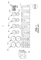
- Each of the colors to be printed is applied in a separate printing station or unit 20, the printing stations or units being disposed along the direction of feed of the sheet 5.
- Examples of printing on the sheet 5 are shown in plan view in the lower part of Fig. 1, each example representing the state of the sheet 5 after completion of the printing stage represented by the printing station or unit 20 of the printer 1 thereabove.
- Fig. 2A shows the relationship of a corrugated cardboard sheet 5 (or "sheet") to the printing cylinder of a printing station 20 of the printer 1.
- a printing area 6, shown as a lined region of the sheet 5, represents that area of the surface of the sheet 5 which may be printed.
- the width of the area to be printed corresponds to the width W of the printing die or plate 23.
- the longer dimension X of the sheet 5 is referred to as the length, and the shorter dimension Y of the sheet 5 is referred to as the width.
- the sheet is fed through the printer 1 in the widthwise direction; that is, the width of the sheet is oriented in the direction of travel of the sheet 5 through the printer 1.
- An side edge of the sheet 5 is also shown in the enlarged insert where the corrugations of approximately sinusoidal shape having an upper and lower liners adhered thereto. As shown, the direction of the corrugations is in the widthwise direction of the sheet 5, such that the successive corrugations are arranged one after another along the length of the sheet.
- the length of the print area 6 determines the circumferential length of the print die or plate 23 at the periphery of the roll 22b.
- the length of the sheet 5 along the direction of travel which may be printed by the printing die or plate 23 depends on the diameter D of the cylindrical roll 22b and the angular extent ⁇ of the periphery occupied by the printing die or plate 23, see Fig.2B.
- the diameter D of the cylindrical roll 22b determines the printing length X of the sheet 5.
- the diameter of the cylindrical roll 22b increases accordingly, and the overall dimensions of the printer 1 may become quite large, and is determined by the longitudinal dimension of the largest sheet that the printer is intended to accommodate.
- the corrugated cardboard sheet 5 may also be fed so that the length X is perpendicular to the direction of feed, as shown in Fig. 1.
- This arrangement results in increasing the width or transverse dimension of the printer 1 in accordance with the maximum length X of sheet 5 to be accommodated by the printer 1.
- Fig. 1 shows a situation where an area on the corrugated cardboard sheet 5, corresponding to the side faces of the completed box 50, are separately printed with different colors, and each color is represented by a different symbol (circle, triangle, square and star).
- each of the faces may be printed with two or more or even all the colors and the example is given for the sake of simplicity.
- the orientation of die corrugated cardboard sheet 5 with respect to the direction of feed may be altered, resulting in a lack of registration of the images or colors.
- ink jet printing technology of corrugated cardboard sheet effects printing in a non-contact manner, ink droplets being ejected from ink jet nozzles toward the surface of the sheet so that in theory they land at predetermined positions and form dots which result in the formation of the desired printing image on the surface.
- Applicant's European published patent applications EP 1 731 318 and 1 733 890 disclose an arrangement of a plurality of ink heads in the transverse direction to enable the desired image to be printed across the entire width of the sheet while permitting continuous movement of the sheet during ink jet printing.
- two rows of print heads arranged adjacent to each other in the transverse direction are offset in the feed direction.
- EP 1 731 318 and EP 1 733 890 disclose using a suction box in communication with suction holes in the conveyor belt for sucking the sheet against the conveyor belt conveying sheets through an ink jet printing unit.
- a pair of 'dampers' is arranged inside the suction box and extends in the longitudinal or feed direction to divide the suction box into suction and non-suction areas.
- the dampers are supported on threaded shafts to adjust their position in accordance with the width of the sheet.
- suction to maintain the sheet in a predetermined, flat position during ink jet printing can, however, affect ink jet droplet trajectories and therefore the quality of the print image, especially when ink jet printing is done in areas close to the longitudinal edges of the sheet or where the sheet is a corrugated cardboard sheet intended for forming a box and has been slotted prior to ink jet printing.
- An object of the present invention is to provide a method and apparatus for printing corrugated cardboard sheets for forming corrugated boxes in succession which eliminates or mitigates such drawbacks.
- Another object of the present invention is to provide a method and apparatus for printing such corrugated cardboard sheets which is capable of ensuring high quality print images in areas of the surface corresponding to side faces of the ultimate corrugated box without the printing apparatus becoming unduly bulky or complex, irrespective of the printing configuration.
- a printer comprising at least one ink jet printing unit having a plurality of ink jet nozzles: a conveyor belt having a direction of travel for conveying corrugated sheets to the ink jet printing unit, perforations or pores extending through the conveyor belt; the plurality of ink jet nozzles being disposed transverse to the direction of travel of the conveyor belt and spaced above or below a liner surface of the corrugated sheet to be printed; a suction chamber in communication with the perforations or pores in the conveyor belt at the ink jet printing unit for applying suction to the corrugated sheet and urging the corrugated sheet against the conveyor belt; and means for selectively controlling the suction area in communication with the perforations or pores in conveyor belt at the ink jet printing unit, so that the transverse dimension of the suction area is substantially less than the width of the corrugated sheet.
- the transverse dimension of the suction area substantially corresponds to the intended printing area on the corrugated sheet.
- the corrugated sheet is slotted to form a box after folding and assembling, the transverse dimension of the suction area is out of communication with the slots in the corrugated sheet. In all cases, the transverse edges of the corrugated sheet at the printing unit should be out of communication with the suction area.
- the suction area is thus defined so that the disturbance caused by air flow generated by suction is reduced or eliminated.
- the means for selectively controlling the section area comprise members for defining transverse limit of the contour of the suction area.
- Such members for defining the suction area may be baffles, also called dampers, for dividing the interior of the suction chamber into zones which respectively are in communication with the exhaust fan or blower and out of communication with an exhaust fan or blower.
- baffles are spaced from each other transversely to the direction of travel of the conveyor belt.
- the nozzles of the ink jet printing unit are spaced above the corrugated sheet at the ink jet printing unit and the corrugated sheet is conveyed by an upper run of the conveyor belt or the nozzles of the ink jet printing unit are spaced below the corrugated sheet at the ink jet printing unit and the corrugated sheet is conveyed by a lower run of the conveyor belt.
- two ink jet printing units are arranged in succession, and each of two conveyor belts conveys the corrugated sheet to a respective ink jet printing unit.
- the nozzles of one of the ink jet printing units are spaced above the corrugated sheet at that ink jet printing unit for printing an upper surface of the sheet and the corrugated sheet is conveyed by an upper run of the associated one of the conveyor belts and the nozzles of the other ink jet printing unit are spaced below the corrugated sheet at the ink jet printing unit for printing a lower surface of the sheet and the corrugated sheet is conveyed by a lower run of the associated one of the conveyor belts.
- a dryer is disposed between the print head of the first printing unit and the print head of the second printing unit.
- the suction chamber may be configured to permit printing of the corrugated sheet in the printing unit having a first dimension in the direction of travel of the conveyor belt which is greater than a second dimension which is transverse to the direction of travel.
- a method of printing on a surface of a corrugated sheet comprising: providing a conveyor belt for conveying corrugated sheets to an ink jet printing unit having an ink jet printing head incorporating a plurality of nozzles; applying suction to a first side of the corrugated sheet through perforations or pores in the conveyor belt; limiting the transverse dimension of the suction area at the ink jet printing unit to be substantially less than the transverse dimension of the corrugated sheet; and printing on a second side of the corrugated sheet opposite the suction area.
- the transverse dimension of the suction area substantially corresponds to the intended printing area on the corrugated sheet.
- the corrugated sheet is slotted and the suction area is out of communication with slots in the corrugated sheet. In all cases the transverse edges of the corrugated sheet at the printing unit are out of communication with the suction area.
- the suction area is defined so that the trajectories of ink droplets ejected from the ink jet nozzles are substantially unaffected by air flow generated by the application of suction to the corrugated sheet at the printing unit whether the suction area corresponds to the intended print area or is out of communication with the slots of a slotted corrugated sheet.
- the corrugated sheet is a corrugated cardboard sheet configured for forming a box or box component and having slots on opposed sides thereof; the printing area of the corrugated sheet being defined by a non-slotted portion corresponding to a side face of the box, and the suction area is defined so that it corresponds to the non-slotted portion, in practice inwardly of the slots.
- the corrugated sheet may be oriented with respect to the direction of travel in accordance with the size of the printing image, the position of the printing image, or the direction of the slots in the corrugated sheet.
- the ink jet nozzles are disposed in groups, each such group having a dimension in the direction transverse to the direction of travel of the corrugated sheet which is less than the transverse dimension of the printing area.
- a gap may be provided between the groups of printing nozzles in the transverse direction, and at least an upstream group of printing nozzles is disposed such that they extend across the gap.
- a printer or printing apparatus comprising a first conveyor belt and a second conveyor belt, disposed in succession along a path of travel of the sheet to be printed; a first suction chamber or box disposed facing one side of a first run of a conveyor belt and a second suction chamber or box facing one side of a first run of the second conveyor belt.
- a first or upper print head is disposed so as to eject ink in a downward direction towards an upper surface of the sheet to be printed; and a second or lower print head is disposed so as to eject ink in an upward direction towards a lower surface of the sheet to be printed.
- a dryer is disposed between one of the print heads and the second conveyor belt.
- a printer or printing apparatus comprising means for conveying a sheet to be printed, a plurality of ink jet nozzles disposed transverse to the direction of travel of the sheet, the ink jet nozzles being spaced from a surface of the sheet to be printed including a first plurality of ink jet nozzles disposed on an opposite side of the sheet to be printed from a second plurality of ink jet nozzles, the sheet to be printed being conveyed between the first and second pluralities of ink jet nozzles by the means for conveying a sheet.
- a method of printing on a surface of a sheet including the steps of providing a conveyor belt with a suction box disposed facing a first side of the conveyor belt; providing an ink jet print head disposed such that the ink jet nozzles are disposed perpendicular to the direction of travel of the conveyor belt; disposing the ink jet print head facing a second surface of the conveyor belt; sensing the position of a first edge of the sheet; and controlling the ink jet print head to eject ink to form an image in accordance with image data received by a print controller.
- corrugated sheet is intended to mean any structure having at least one liner and one corrugated core or structure, the liner and the corrugated core or structure being integral or co-joined by fixing means such as an adhesive, an interlayer or the like.
- Such corrugated sheets are commonly made from cellulose-based materials, but as used herein the term is not intended to exclude other materials such as plastics, staple fibers, or other combinations of materials that may be formed into corrugated sheets.
- a corrugated sheet has at a minimum one liner and one corrugated core or structure, and typically one liner on either side of the corrugated core or structure but may include multiple layers of each type and with various means for joining the layers together.
- sheet as used herein means a corrugated sheet having one or two liners, a flat sheet or liner, or assemblies of corrugated sheets, corrugated cores or structures and flat sheets or liners.
- the corrugations may be sinusoidal, crenellated, triangular or the like.
- the sheet may be cellulose-based, plastic, fibrous or the like and may be a combination of a variety of materials such that a surface suitable for printing is formed.
- image includes a picture, a drawing, a geometric or abstract design, and/or text, and be of one or more colors to be formed from the sheet. More than one image may be combined for printing on a surface of the sheet to be printed corresponding to a face of the box or container formed from the sheet.
- a sheet 5 is printed in a non-contact manner such that ink droplets are ejected from ink jet nozzles towards the surface of the sheet 5 to land at predetermined positions and thus form dots on the surface thereof.
- ink jet nozzles are arranged across the width of the sheet 5, corresponding to area(s) to be printed. Generally, a plurality of nozzles are used and disposed so as to provide zones of coverage of the printing area.
- Fig. 3 is a schematic diagram of an ink-jet printing system 100, including a feeder 112 having a kicker 213 for feeding corrugated sheets 5 in succession or one by one from a stack of sheets 113, an inkjet printing unit 114 for printing a surface of the sheet 5.
- the printed sheets exiting from the printing area may be stacked by a stacker (not shown) and then further processed using another feeder 112, having a kicker 213, and a scorer 30 and a slotter 40, so as to prepare the sheet 5 to be formed into a box 50.
- the sheets 5 may be stored after creasing and slotting steps and formed into boxes 50 at some later stage, and at a different location. Alternatively, the sheets to be printed may be creased or scored and slotted prior to printing.
- a conveyor 180 receives a sheet 5 from the feeder 112 and moves the sheet 5 at a uniform velocity v beneath the ink jet printing unit 114, which may have a plurality of nozzles (not shown) arranged so as to dispense ink of one or more colors.
- a print controller 141 accepts image data from a server, communications system or the like and converts the image data into a format compatible with the printer 100. This may include converting from a red (R), green (G), blue (B) color format typical of video displays to the YMCK (yellow, magenta, cyan, and black) format.
- the print controller may be a microprocessor, computer, or similar device having appropriate electrical interface and associated memory, which may be volatile or non-volatile memory as is known in the art.
- Image data may be considered to represent any type of printed image, including text, graphics, photographs, computer generated art, or the like, and combinations thereof, which may be represented by a pattern of ink dots on a surface.
- the functions, acts or tasks are independent of the particular type of instruction set, storage media, processor or processing strategy and may be performed by software, hardware, integrated circuits, firmware, micro code and the like, operating alone or in combination.
- processing strategies may include multiprocessing, multitasking, parallel processing and the like.
- the instructions may be stored on a removable media device for reading by local or remote systems.
- the instructions may stored in a remote location for transfer through a computer network, a local or wide area network, a wireless network, or over telephone lines.
- the instructions are stored within a given computer or system.
- actions performed under the control of a computer may equally be performed under the control of programmable logic, and by other means including analogue circuitry and mechanical analogues of these devices.
- Fig. 4 is a more detailed example of an ink-jet printer 100.
- a feeder 112, a printing station or unit 114, and a stacker 116 for stacking the printed sheets 5 are arranged in the direction of feeding, or the feed direction, of the sheets.
- the feeder 112 includes a hopper 118 in which the sheets 5 are received prior to feeding into the printing zone; a first transport mechanism 180 comprising, for example, a conveyor mechanism, that transports individual sheets 5 from the hopper 118 towards the printing station or unit 114; and, a second transport mechanism 190 comprising, for example, a conveyor mechanism, that transports each successive fed sheet 5 beneath the print heads 140, located at the printing station or unit 114.
- a conveyor 120 is disposed so that sheets 5 being fed from the hopper 118 are further transported through the printing station or unit 114.
- the conveyor 120 may comprise a plurality of parallel conveyor belts 120a, as shown, disposed between pulleys or rollers 123 and 124, each having an upper run facing the printing heads 140 and a lower run, spaced below the upper run and travelling in an opposite direction to the upper run.
- the conveyor may comprise a single belt (not shown), having a width or transverse dimension substantially equal to the combined width or transverse dimension across the entire plurality of belts.
- the conveyor belts are configured so as to be able to admit the flow of air through at least a perforate or porous portion of the transverse dimension thereof, the perforate or porous portion comprising perforations (also called apertures or holes) 135 or simply pores.
- a plenum chamber 147 may be disposed below a portion of the upper run of the conveyor belts 120a so as to apply suction to the underside of the upper run of the conveyor belts 120a through a suction chamber 129.
- a blower or exhaust fan 149 is connected to the plenum chamber 147 and operated so as to exhaust air from the plenum chamber 147.
- the suction chamber or box 129 is connected to or in communication with the plenum chamber 147 by means of a conduit 150 (shown in Fig.
- the sheet 5 When a sheet 5 is disposed on the upper run of the conveyor belts 120a, the sheet 5 may overlie spaces between individual belts 120a of the conveyor 120, or in the case of a single broad conveyor belt (not shown) may overlie a portion thereof corresponding to the transverse extent of the sheet 5.
- Selective control of the suction area applied through perforations or pores in the conveyor belts or conveyor belt is provided as illustrated by a pair of partitions or baffles 81 and shown in Fig. 6 is disposed beneath the upper run of the conveyor belts so as to limit the flow of air from areas of the conveyor belts or conveyor belt which are not covered by the width of the sheet 5.
- the transverse distance between the baffles or partitions 81 is adjusted to be less than the transverse dimension or width of the sheet 5, and may be set to a distance approximately corresponding to the transverse dimension or width of the printing area.
- the baffles or partitions 81 restrict the air flow such that air is preferentially drawn from the region between the baffles or partitions as compared with regions beyond the baffles or partitions.
- the air pressure differential between the ambient environment above the sheet 5 and the bottom surface of the sheet 5 positioned between the baffles 81 presses the sheet 5 against the conveyor belts 120a.
- the amount of air drawn from beyond the region between the two baffles or partitions 81 may be minimized, so as to reduce the air flow in the vicinity of the printing heads 140 and thereby reduce or eliminate disturbances to ink jet drop trajectories.
- At least one of conveyor pulleys or rolls 123 and 124 is rotatably driven by a motor so as to cause the linear travel of the conveyor belts 120a in the feed direction shown by the arrows.
- the motor may be a stepping motor, or other rotary device as is known in the art, or the pulleys or rolls may be coupled to a prime mover such as an electric motor (not shown) by gears or belts, or the like.
- the lower surface of the sheet 5 which is pressed down against the upper surface of the upper runs of the conveyor belts 120a, is transported through the printing unit 114.
- the inkjet printing unit 114 may include sets of ink jet heads 140a, 140b disposed so as to be oriented with the ink jet nozzles thereof extending in lines perpendicular to the direction of travel of the sheet 5 and further disposed above the sheet 5 as it passes beneath the heads 140 along the direction of travel through the printing station or unit 114.
- a suction chamber 129 is disposed on the underside of the upper runs of the conveyor belts 120a that is the side of the sheet 5 which faces away from the ink jet heads 140.
- the printing station or unit 114 may have sets of ink jet heads 140 disposed above the sheet 5 and facing the upper surface of the sheet 5, that is, facing away from the conveyor belts 120a and the suction chamber 127.
- the ink jet heads 140 are oriented and controlled such that the ink droplets are ejected downwardly so as to form dots with the desired density (dots per inch, DPI) and color on the upper surface of the sheet 5.
- DPI density
- Fig. 4 there are two sets of ink jet heads 140a and 140b, each set of heads having groups of nozzles 144Y, 144M, 144C and144K (such as shown in Fig. 5a), corresponding to the yellow (Y), magenta (M), cyan (C) and black (K) ink.
- the nozzles 144 are disposed such that the ink-jet nozzles for each of the colors YMCK are parallel to each other, and the nozzles for each of the colors are separated by a distance in the feed direction of the sheet 5.
- a controller 141 controls the action of the nozzles 144 so as to deposit the ink droplets in the proper locations to form the image desired.
- the ink jet nozzles 144 are disposed a known distance from the upper surface of the sheet 5, and the vertical position of the ink jet heads 140 may be adjusted to take into account the thickness of the sheet 5.
- Motorized adjustment screws 191a-d driven by motors 192a-d, respectively, may be used to adjust the distance of the ink jet nozzles 144 from the upper surface of the sheet 5 by raising and lowering the platform 190, on which the ink jet heads 140 are mounted. In this manner, a desired distance between the ink jet nozzles 144 and the upper surface of the sheet 5 may be established, depending on the thickness of the sheet 5 to be printed.
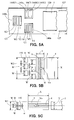
- Figs. 5A-C illustrate several different arrangements of the printing heads 140 and orientations of the sheet 5.
- Fig. 5A is a partial plan view of the printing station or unit 114, showing only the print heads 140, a simplified representation of the conveyor 120, the sheet 5, and, optionally, sheet guides 127a.
- the width or transverse dimension of the sheet 5 to be printed corresponds to three separate ink jet print heads, two ink jet print heads 140a1 and 140a2 being disposed in a line transverse to the direction of travel of the sheet 5, and ink jet print head 140b1, which is located along the centerline of the feed path, and downstream or beyond the ink jet heads 140a1 and 140a2.
- ink jet head 140b1 is disposed so that a print area of a sheet traversing the printing station or unit 114 may be printed by at least one of the print heads 140, resulting in a continuous widthwise image in the width region encompassed by the print heads 140.
- the print controller 141 manages the printing process so as to resuit in the proper density and spacing of ink dots to print the desired image.
- Each of the print heads 140 includes a row of nozzles for each of the YMCK print colors to be used.
- Figs. 5B and 5C show arrangement of print heads which may be used depending on the orientation of the sheet 5 passing through the printing station or unit 114.
- Fig. 5B shows an arrangement of the sheet 5 where the length direction X of the sheet 5 is perpendicular to the direction of travel or feed direction of the sheet (shown by the arrowhead Vo).
- Each of the print heads 140 has a transverse dimension W, and a transverse space ⁇ between each other. Two groups of three print head 140 are disposed so that the total width W2 of six print heads spans the length dimension X of the sheet 5, or at least that portion of the length dimension to be printed.
- Fig. 5C illustrates an arrangement of print heads 140 corresponding to the situation where the sheet 5 is oriented such that the width direction Y of the sheet is perpendicular to the feed direction of the sheet (shown by the arrowhead Vo).
- the arrangement of three print heads 140, as shown also in Fig. 5A is sufficient to print the same or similar print area 6 of the sheet 5.
- the sheet 5 may be held tightly against the conveyor belt 120a by the suction provided by the suction chamber 129 and the plenum 147 so that the distance between an upper surface of sheet 5 and the ink jet nozzles 144 remains substantially constant.
- Undesirable air flow associated with the suction process may be mitigated, and the overall air flow volume required may be reduced by the use of selective suction control means such as baffles or partitions 81 in the suction box 129.
- Figs. 6A and 6B illustrate an embodiment of the selective suction control means comprising a suction box and baffles or partitions 81 for the arrangements shown in Figs. 5B and 5C, respectively.
- the sheet 5 may be oriented with either the length dimension X or the width direction Y in the direction of travel with respect to the printing heads. Where the orientation is such that the length dimension is in the direction of travel, the width of the printer 100, and distance between the baffles or partitions 81 of the suction box 129 is less than that when the width dimension Y of the sheet 5 is parallel to the direction of travel. In addition, the gap between successive sheets 5 in the feed direction is also reduced when the length dimension X of the sheet is parallel to the feed direction. In this case, the amount of air flowing in the vicinity of the printing heads 140 may be reduced and the print quality may be improved.
- one or more print head assemblies may be used to provide coverage of the entire transverse dimension of the print area. Economic considerations may lead to the use of multiple print heads aligned in a direction transverse to the direction of travel of the sheet 5. Where multiple print heads 140 are used, a transverse gap may be provided between adjacent print heads 140. A second row of print heads 140 may be provided so that the transverse gap is covered by the second row of print heads. In such a situation, the operation of the print heads may be coordinated so that the print areas or zones covered by overlapping print heads have a density of ink which is consistent with or comparable to the ink density in print areas covered by a single print head.
- Fig. 6A illustrates a plan view of the configuration of the transport or conveyor mechanism 190 where the sheet 5 is oriented with the length direction X in the feed direction.
- the transverse dimension W of the intended print area 6 is shown.
- Dotted lines extending from the end of the sheet 5 towards the transport or conveyor mechanism 190 show the alignment of the intended print area 6 with the baffles or partitions 81.
- the top of the suction chamber 129 may be comprise a perforate member or be entirely open or open only in the regions underneath the individual belts 120a of the conveyor 120.
- Baffles or partitions 81 may include at least two vertical plates extending in a line and underneath the portion of the belts 120a contacting the sheet 5 to a location near a bottom surface of the suction chamber 129, to restrict or eliminate the flow of air through outlying regions 129a, while providing access for air from the exterior environment to enter region 129b and thence to the plenum 147.
- a conduit 150 (see Fig.7) provides communication between the suction chamber or box 129 and the plenum 147 and thereby permits air flow therebetween. Sufficient clearance is provided between the suction chamber or box 129 for the conveyor belts 120a and other parts of the printer. As illustrated, the upper wall of the suction chamber or box has apertures or openings in communication and in alignment with the perforations in the conveyor belts.
- Fig. 6B illustrates the sheet 5 disposed such that its width dimension Y is parallel to the feed direction.
- the intended print area 6 has the same dimensions as in Fig. 6A. In this case, contrary to the arrangement shown in Fig.6A the larger dimension of the intended print area 6 is perpendicular to the feed direction.
- the maximum transverse dimension of the printing area 6 is extended by dotted lines to show the correspondence with respect to the position of the baffles or partitions 81, where the baffles or partitions 81 are adjusted to provide a suction area under the entire printing area 6.
- the longitudinal dimension of the printing area 6 is as long as the maximum length dimension X of the sheet 5, rather than a portion of the width dimension Y. In this case, the amount of air drawn into the suction chamber 129 is greater.
- the baffles or partitions 81 are moved nearer to the edges of the sheet 5, air flow in this region may be greater than in the case illustrated in Fig. 6A.
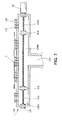
- Fig. 7 shows an embodiment of the means for selectively controlling the suction area transversely to the feed direction where members such as baffles or partitions 81 L and 81 R are threadedly engaged with screw shafts or threaded rods 132 extending transverse to the feed direction.
- Each screw shaft 132 has a left-hand threaded portion132L and a right-hand threaded portion 132R, having opposite thread senses, but as shown are part of a single rotatable shaft supported by a bearing 133 at one end thereof.
- the screw shaft 132 may be rotatably driven by a motor 82, or manual means disposed at an opposite end of the shaft 132.
- the transverse distance between the baffles or partitions 81L and 81 R is increased or decreased.
- the transverse spacing between the baffles or partitions 81 has been set such that each of the baffles or partitions 81 is in line with the dotted lines marking the outer limits of the printing area 6 in the transverse direction.
- the suction applied in suction area 129b is predominantly to the portion of the sheet 5 beneath the print heads 140 and corresponding to the print area 6 on which a printing process is to be performed, holding that portion of the sheet tightly against the conveyor belt and reducing the volume of air flowing into the plenum 147.
- the configuration and effective dimensions of suction area 129b may therefore be sized or adjusted to the transverse dimension of the print area 6. With such an arrangement the air flow generated by the applied suction reduces or eliminates disturbances in the ink droplet trajectories.
- Slots are typically formed in the sheet 5 by a slotter 40 to permit the sheet 5 to be formed into a box 50.
- the slots may be formed either prior to or subsequent to feeding the sheets 5 through a printing apparatus or printer 100, 200. Where the sheet 5 has been slotted prior to feeding through the printer, the sheet may be oriented so that, when the sheet 5 is fed in the direction of feeding, the slots are disposed further from the centerline of the printer so that the selective suction operative between baffles 81 lies between the slots and the centerline of the printer and in the illustrated embodiment, the baffles or partitions, lie between the slots and the center line of the printer. In this case, suction is applied to an unslotted surface of the sheet 5. With such an arrangement the air flow generated by the applied suction reduces or eliminates disturbances in ink droplet trajectories.
- a printing apparatus or printer 200 may be configured to print a sheet 5 on both sides thereof in a single pass of the sheet 5 thought the printer 200.
- Many of the aspects of the printer 200 are similar to those of the printer 100, and only the significant differences will be described. Further, the aspects related to feeding from the input sheet supply, the stacking of the output and subsequent operations, are not shown.
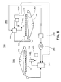
- the printing apparatus or printer 200 shown in Fig. 8 has two sets of print heads 140U and 140L, disposed to face opposite surfaces of the sheet 5. A single sheet 5 is shown in a position such that it is disposed between the print heads 140U and 140L.
- a first conveyor belt 240 and a second conveyor belt 250 are driven by stepping motors (not shown) which in turn are driven by pulse generators 255, and there may be one or more idler pulleys or wheels 257.
- a first suction chamber 260 and a second suction chamber 265 are disposed respectively beneath the upper runs of the conveyor belts 240 and 250 such that the sheet 5 is pressed against the upper surface of the conveyor belts 240, 250 by the differential in air pressure existing between the ambient environment and the air pressure prevailing inside the suction chambers 260, 265.
- the motion of the conveyor belts 240, 250 is such that the sheet 5 moves from right to left (as shown) through the printer 200 when the stepper motors are energized.
- the upper and lower print heads 140U and 140L are supplied with ink from ink reservoirs 145U and 145L, and the printing action of the upper and lower print heads 140U and 140L are controlled by a first print controller 146 and a second print controller 147, respectively. Either or both sides of the sheet 5 may be printed in one pass through the printer 200, in accordance with the desired images to be printed on the sheet 5.
- a sensor 150 which may be an optical sensor, or the like, determines the time when the leading edge of the sheet 5 is at a predetermined distance from the print heads 140U and 140L, and actuates the ink jet nozzles 144 accordingly to produce the images desired.
- a tachometer or shaft encoder may be connected to one or more of the idler or driving pulleys 256, 257 to measure the speed of the conveyor belts 240, 250.
- the print controllers 146, 147 may use the sensor output of the detection of the leading edge of the sheet and the speed of advance of the sheet 5 to determine the time to commence printing. It should be appreciated that the relative registration of the colors, in forming an image, is related predominantly to the accuracy of relative positioning of the print heads 140, and a constant feed velocity v. This same type of control mechanism can be applied to any of the printers in the examples herein. Alter printing, the sheets may be stacked prior to further operation such as scoring and slotting. Alternatively, these operations may be performed as part of a continuous sequential process.
- the printed image on the bottom side of the sheet 5 may be smudged or blurred if the ink is not sufficiently dry by the time the printed area contacts the second conveyor belt 250.
- a dryer 270 may be positioned between the lower print head 140L and the second conveyor belt 250 to accelerate the drying of the ink.
- the dryer may be of any suitable type employing hot air, microwave energy, infra-red or ultraviolet radiation or the like, so long as the sheet can be effectively dried so as to avoid smudging.
- print head 140L may be located closer to the upstream end of the first conveyor belt 240 than to the second conveyor belt 250 so as to increase the ink drying time.
- the vertical position of the upper print head 140U may be adjusted to achieve an optimal printing distance with respect to the facing surface of sheet 5, taking account of the thickness of sheet 5.
- the distance between the lower print head 140L and the lower facing surface of the sheet 5 may not be adjusted, as that distance does not change with sheet thickness.
- printer 200 may apply printing to both surfaces of a sheet 5 in a single operation, where different images may be printed in accordance with the data and instructions furnished to the print controllers 146 and 147.
- the print controllers 146, 147 may receive data for controlling the printer and the images to be printed from a server 290 or other computer, and the server 290 or other computer may be either local or remotely located.
- the connection between the server 290 and the print controllers 146 and 147 may be over a local area network, a wide area network 290 such as the Internet, or by wireless communication techniques.
- two sequentially disposed printing units 300U and 300L may be used to print two surfaces of the sheet 5 in one operation. As in the previous examples, only one side may be printed if the print instructions do not require printing on both sides of the sheet 5. Only significant differences between the printer 300 and the previous examples will be described.
- the printer 300 thus includes an upper printing unit 300U and a lower printing unit 300L.
- the feeder, the stacker, the creaser and slotter are not shown, but have been illustrated and described in the previous examples.
- the upper printer 300U is substantially the same as printer 100 and serves to print on an upper surface of sheet 5.
- a dryer 380 is disposed between the print head 140U on the printer 300U and the upstream end of the lower run of the second conveyor belt 350 of the printer 300 L.
- the dryer 380 is disposed such that the ink that was used to print the image on the upper surface of the sheet 5 is sufficiently dry so that the ink is not smudged or blurred by contact with the second conveyor belt 350, that is when the sheet is held against the conveyor belt 350 by the differential in air pressure between the ambient environment and the suction chamber 370 associated with the second printer 300L.
- Print head 140L is disposed below the sheet 5 in the second printing unit so that the side that was not printed in the first printing unit 300U is printed in the second printing unit 300L.
- the order of the printing units 300U and 300L is indifferent, but the first printed side should be sufficiently dry when it contacts the conveyor belt of the second printer so that smudging or blurring is avoided.
- each of the print heads may be capable of adjustment in the vertical direction so as to accommodate sheets 5 of varying thickness, from print job to print job.
- the distance adjustment may be performed manually, or by a mechanism under the control of the print controllers.
Landscapes
- Ink Jet (AREA)
- Handling Of Sheets (AREA)
- Making Paper Articles (AREA)
- Delivering By Means Of Belts And Rollers (AREA)
- Ink Jet Recording Methods And Recording Media Thereof (AREA)
Applications Claiming Priority (1)
| Application Number | Priority Date | Filing Date | Title |
|---|---|---|---|
| US11/409,551 US8353591B2 (en) | 2006-04-20 | 2006-04-20 | Apparatus and method for printing corrugated cardboard sheets |
Publications (2)
| Publication Number | Publication Date |
|---|---|
| EP1847397A2 true EP1847397A2 (de) | 2007-10-24 |
| EP1847397A3 EP1847397A3 (de) | 2008-06-25 |
Family
ID=38292672
Family Applications (1)
| Application Number | Title | Priority Date | Filing Date |
|---|---|---|---|
| EP07106574A Withdrawn EP1847397A3 (de) | 2006-04-20 | 2007-04-20 | Vorrichtung und Verfahren zum Bedrucken von Wellpappe |
Country Status (6)
| Country | Link |
|---|---|
| US (1) | US8353591B2 (de) |
| EP (1) | EP1847397A3 (de) |
| JP (1) | JP4923296B2 (de) |
| CN (2) | CN101058244A (de) |
| AU (1) | AU2007201656A1 (de) |
| RU (1) | RU2007114847A (de) |
Cited By (14)
| Publication number | Priority date | Publication date | Assignee | Title |
|---|---|---|---|---|
| WO2012152481A1 (de) * | 2011-05-06 | 2012-11-15 | Robert Bosch Gmbh | Verfahren zum bedrucken von zumindest einem trägerelement |
| WO2012168020A1 (de) * | 2011-06-10 | 2012-12-13 | Theodor Hymmen Verwaltungs Gmbh | Verfahren zum bedrucken von werkstücken und druckvorrichtung |
| GB2493208A (en) * | 2011-07-28 | 2013-01-30 | Ds Smith Packaging Ltd | Apparatus and method for producing printed articles |
| ITPD20120046A1 (it) * | 2012-02-23 | 2013-08-24 | Silvano Lovato | Attrezzatura per la stampa su carta per la realizzazione di borse di carta |
| EP2918529A3 (de) * | 2014-03-11 | 2015-09-30 | Sun Automation, Inc. | Fördervorrichtung und Verfahren zum Transport von Artikeln entlang eines im Wesentlichen horizontalen Wegs |
| EP2946937A1 (de) * | 2014-05-21 | 2015-11-25 | Jet-Set Srl | Druckvorrichtung und zugehöriges verfahren |
| WO2016008597A1 (fr) * | 2014-07-18 | 2016-01-21 | Bobst Mex Sa | Caisson d'aspiration pour système de transport de supports plans et machine d'impression ainsi équipée |
| WO2016008596A1 (fr) * | 2014-07-18 | 2016-01-21 | Bobst Mex Sa | Caisson d'aspiration, systeme de transport de supports plans, et machine d'impression ainsi equipee |
| EP3037271A1 (de) * | 2014-12-23 | 2016-06-29 | Jet-Set Srl | Druckeinheit für eine druckvorrichtung und druckvorrichtung mit dieser druckeinheit |
| EP3392048A1 (de) * | 2017-04-20 | 2018-10-24 | HP Scitex Ltd | Medienunterstützung |
| EP3428095A1 (de) * | 2017-07-10 | 2019-01-16 | HP Scitex Ltd | Transport von blättern von druckmedien |
| EP3825136A1 (de) * | 2019-11-21 | 2021-05-26 | Jesús Francisco Barberan Latorre | Vakuumsystem zur sicherung von substraten |
| CN114347662A (zh) * | 2021-11-25 | 2022-04-15 | 司志涛 | 基于瓦楞纸板的数码打印系统及数码打印方法 |
| WO2022079633A1 (en) * | 2020-10-13 | 2022-04-21 | Panotec S.R.L. | Machine for forming and printing cardboard boxes |
Families Citing this family (67)
| Publication number | Priority date | Publication date | Assignee | Title |
|---|---|---|---|---|
| JP4671773B2 (ja) * | 2005-06-10 | 2011-04-20 | 株式会社Isowa | 印刷装置 |
| JP2007175948A (ja) * | 2005-12-27 | 2007-07-12 | Fujifilm Corp | インクジェットプリンタ |
| US20070206038A1 (en) * | 2006-03-03 | 2007-09-06 | Richard Baker | Ink jet printing with multiple conveyors |
| US20090160889A1 (en) * | 2007-12-24 | 2009-06-25 | Pitney Bowes Inc. | Method and apparatus for printing on variable thickness print media |
| WO2009149163A2 (en) * | 2008-06-06 | 2009-12-10 | Fujifilm Dimatix, Inc. | Sensing objects for printing |
| EP2496421B1 (de) * | 2009-07-31 | 2015-06-24 | Memjet Technology Limited | Drucksystem mit fixen druckköpfen und beweglichen vakuumplatten |
| WO2012159130A2 (en) * | 2011-05-19 | 2012-11-22 | FINATZER, Barbara Anne | Conveyor belt section |
| JP2012250384A (ja) * | 2011-06-01 | 2012-12-20 | Ricoh Co Ltd | 画像形成装置 |
| CN102350874B (zh) * | 2011-06-27 | 2014-09-17 | 合肥奥瑞数控科技有限公司 | 数控喷墨绘图及激光切割一体机 |
| CN102874620B (zh) * | 2011-07-15 | 2015-03-11 | 玉田元创包装机械制造有限公司 | 一种全自动卡片输送检测定位装置 |
| CN102491114A (zh) * | 2011-11-14 | 2012-06-13 | 瑞安市博业激光应用技术有限公司 | 无版数码印刷机的纸板传送系统 |
| JP5919762B2 (ja) * | 2011-11-29 | 2016-05-18 | ブラザー工業株式会社 | 印刷制御装置および印刷装置 |
| JP6032003B2 (ja) | 2012-03-30 | 2016-11-24 | ブラザー工業株式会社 | インクジェットプリンタ、インクジェットプリンタのギャップ情報取得方法、及び、液体吐出装置 |
| JP6028565B2 (ja) | 2012-03-30 | 2016-11-16 | ブラザー工業株式会社 | インクジェットプリンタ、インクジェットプリンタのギャップ情報取得方法、及び、液体吐出装置 |
| US8882215B2 (en) | 2012-03-30 | 2014-11-11 | Brother Kogyo Kabushiki Kaisha | Method and inkjet printer for acquiring gap information |
| JP5803785B2 (ja) | 2012-03-30 | 2015-11-04 | ブラザー工業株式会社 | インクジェットプリンタ |
| JP6115128B2 (ja) | 2012-03-30 | 2017-04-19 | ブラザー工業株式会社 | インクジェットプリンタのギャップ情報取得方法、インクジェットプリンタ、及び、液体吐出装置 |
| US8939574B2 (en) * | 2013-02-25 | 2015-01-27 | Memjet Technology Ltd. | Printer with vacuum belt assembly having non-apertured belts |
| CN103389033A (zh) * | 2013-06-27 | 2013-11-13 | 蚌埠申徽彩色印刷包装有限公司 | 一种喷墨测距装置 |
| US9446608B2 (en) * | 2014-05-30 | 2016-09-20 | Eastman Kodak Company | System for generating vacuum response curves |
| JP6456631B2 (ja) * | 2014-09-03 | 2019-01-23 | 理想科学工業株式会社 | シート状物搬送装置及びインクジェット印刷装置 |
| CN105799204A (zh) * | 2014-12-31 | 2016-07-27 | 天津市振宇恒裕科技有限公司 | 一种包装盒印刷工艺 |
| CN105398214B (zh) * | 2015-07-16 | 2017-12-26 | 中山市佑崴自动化科技有限公司 | 立式双面镭射喷码机 |
| RU2609179C1 (ru) | 2015-09-04 | 2017-01-30 | Виктор Владимирович ИСУПОВ | Способ печати на струйном 3d-принтере |
| CN106494085B (zh) * | 2015-09-07 | 2018-09-28 | 深圳市万德环保印刷设备有限公司 | 一种瓦楞纸板数码印刷机 |
| DE102015218338A1 (de) * | 2015-09-24 | 2017-03-30 | Bhs Corrugated Maschinen- Und Anlagenbau Gmbh | Wellpappeanlage |
| DE102015219630A1 (de) * | 2015-09-24 | 2017-03-30 | Bhs Corrugated Maschinen- Und Anlagenbau Gmbh | Wellpappe-Anlage |
| DE102015218316A1 (de) * | 2015-09-24 | 2017-03-30 | Bhs Corrugated Maschinen- Und Anlagenbau Gmbh | Wellpappe-Anlage |
| DE102015218333A1 (de) * | 2015-09-24 | 2017-03-30 | Bhs Corrugated Maschinen- Und Anlagenbau Gmbh | Wellpappeanlage |
| ITUB20154240A1 (it) * | 2015-10-08 | 2017-04-08 | Aleph S R L | Stampante a getto di inchiostro |
| CN108349266A (zh) * | 2016-01-28 | 2018-07-31 | 惠普发展公司有限责任合伙企业 | 关于纸箱衬里的瓦楞板轧制机控制信息 |
| ITUA20161432A1 (it) * | 2016-03-07 | 2017-09-07 | Siti B & T Group Spa | Pressa per la realizzazione di prodotti ceramici |
| EP3463914B1 (de) * | 2016-05-24 | 2020-10-07 | Koenig & Bauer AG | Bogendruckmaschine |
| CN106739547B (zh) * | 2016-09-06 | 2018-09-21 | 深圳汉华工业数码设备有限公司 | 一种数码印刷设备 |
| JP6995331B6 (ja) * | 2016-11-29 | 2022-01-28 | 株式会社Isowa | フォルダグルア |
| CN106515084A (zh) * | 2016-12-09 | 2017-03-22 | 重庆锦沙沣包装有限公司 | 纸箱成型装置 |
| EP3437887B1 (de) * | 2017-07-31 | 2022-03-30 | HP Scitex Ltd | Verfahren und drucksystem zum abscheiden von druckflüssigkeit auf einem blatt von wellmedium |
| CN107757122A (zh) * | 2017-10-30 | 2018-03-06 | 平湖市燎原印刷厂 | 一种可自动清洗干燥的印刷装置 |
| CN109049838A (zh) * | 2018-09-17 | 2018-12-21 | 嘉兴臻胜包装科技有限公司 | 一种纸箱的水性印刷装置 |
| CN109080225A (zh) * | 2018-10-23 | 2018-12-25 | 东莞市厚威包装科技股份有限公司 | 一种纸卡板的纸脚墩自动压紧设备及压紧方法 |
| IT201800020215A1 (it) * | 2018-12-19 | 2020-06-19 | Keraglass Ind S R L | Macchina di stampa a getto di inchiostro su lastre |
| CN109774252A (zh) * | 2019-03-06 | 2019-05-21 | 泰州永盛包装股份有限公司 | 一种节能型瓦楞纸板单面瓦加工设备 |
| CN109849423B (zh) * | 2019-03-08 | 2020-10-16 | 杭州富庆纸制品有限公司 | 一种用于瓦楞纸箱的自动生产流水线系统 |
| CN110039831A (zh) * | 2019-04-02 | 2019-07-23 | 江西新明峰包装科技有限公司 | 内补强装置 |
| EP3753739B1 (de) * | 2019-06-17 | 2023-01-25 | Agfa Nv | Verfahren zum dekorieren einer verpackungsschachtel |
| NL2023752B1 (en) * | 2019-09-03 | 2021-04-13 | Xeikon Mfg Nv | Printing method |
| KR102073648B1 (ko) * | 2019-10-14 | 2020-02-05 | 심백만 | 포장박스용 인쇄 장치 |
| CN110877474B (zh) * | 2019-11-06 | 2021-08-27 | 潍坊泰利包装有限公司 | 一种包装纸箱的印刷装置及其生产方法 |
| US11318760B2 (en) | 2019-12-23 | 2022-05-03 | Xerox Corporation | Media transport belt that attenuates thermal artifacts in images on substrates printed by aqueous ink printers |
| CN111016274A (zh) * | 2019-12-27 | 2020-04-17 | 珠海市腾裕包装制品有限公司 | 一种具有调节机构的包装纸板开槽装置 |
| JP7384676B2 (ja) * | 2020-01-15 | 2023-11-21 | 小池酸素工業株式会社 | 印字装置及び印字設備 |
| JP7267217B2 (ja) * | 2020-01-31 | 2023-05-01 | 三菱重工機械システム株式会社 | インクジェット印刷装置、製函機およびコルゲートマシン |
| US11052678B1 (en) | 2020-02-06 | 2021-07-06 | Xerox Corporation | Dryer platensthat attenuate image defects in images printed on substrates by aqueous ink printers |
| CN111619216A (zh) * | 2020-06-24 | 2020-09-04 | 河北林成包装机械制造有限公司 | 瓦楞纸板成型印刷一体生产线及使用方法 |
| US11161355B1 (en) | 2020-07-08 | 2021-11-02 | Xerox Corporation | Media transport through a dryer that attenuates thermal artifacts in images on substrates printed by aqueous ink printers |
| CN111959125A (zh) * | 2020-07-13 | 2020-11-20 | 上海至亲印刷科技有限公司 | 高效喷墨印刷机 |
| US11440210B2 (en) | 2020-10-19 | 2022-09-13 | Tilia Labs Inc. | Automating the planning, estimating, and impositioning of printer orders via multi-step cutting that involve die cutting |
| CN112847627B (zh) * | 2020-12-22 | 2023-08-15 | 广东爱明科技有限公司 | 一种纸制品加工压痕打孔设备 |
| CN112874161B (zh) * | 2020-12-31 | 2022-01-14 | 江苏瑞彩包装有限公司 | 一种喷码印刷机 |
| CN113064592B (zh) * | 2021-03-31 | 2025-02-11 | 新代科技(苏州)有限公司 | 开槽机图形导入编程方法及系统 |
| CN113371481B (zh) * | 2021-06-16 | 2022-09-02 | 深圳汉华工业数码设备有限公司 | 整形机构及印刷系统 |
| US11685157B2 (en) * | 2021-07-12 | 2023-06-27 | Electronics For Imaging, Inc. | Upwards jetting digital printing platform |
| CN113665173A (zh) * | 2021-08-17 | 2021-11-19 | 漯河市信和包装有限公司 | 一种纸盒包装箱生产用纸板双面印刷设备及印刷工艺 |
| CN114228252A (zh) * | 2021-12-24 | 2022-03-25 | 扬州东兴印刷包装有限公司 | 一种用于环保包装盒的绿色速干印刷工艺 |
| CN115674904B (zh) * | 2022-11-21 | 2025-04-22 | 龙利得智能科技股份有限公司 | 一种改进型瓦楞纸喷印装置 |
| WO2024133178A1 (en) * | 2022-12-22 | 2024-06-27 | Bobst Mex Sa | Digital printing module for a converting machine |
| CN119427965B (zh) * | 2025-01-10 | 2025-04-01 | 宣城市博思特日用品有限公司 | 一种喷涂装置及用于纸杯生产的图案喷涂工艺 |
Family Cites Families (46)
| Publication number | Priority date | Publication date | Assignee | Title |
|---|---|---|---|---|
| US3189502A (en) * | 1961-03-03 | 1965-06-15 | West Virginia Pulp & Paper Com | Method of making impregnated corrugated paperboard sheets on a corrugator machine |
| US3493122A (en) * | 1968-10-14 | 1970-02-03 | Lee C Mckee | Tray |
| US3741117A (en) * | 1970-07-10 | 1973-06-26 | Sinclair & Valentine Co Inc | Pressureless non contact electrostatic printing |
| US4059220A (en) | 1976-07-14 | 1977-11-22 | Macmillan Bloedel Containers, Inc. | Reinforced single-face corrugated containers |
| US4339292A (en) * | 1979-06-27 | 1982-07-13 | Kyokuto Fatty-Acid Corporation | Method for producing a reinforced, double-faced corrugated board |
| US4792249A (en) * | 1985-09-20 | 1988-12-20 | Creative Associates Limited Partnership | Vacuum paper transport system for printer |
| US4992805A (en) * | 1987-08-14 | 1991-02-12 | Canon Kabushiki Kaisha | Image recording apparatus |
| JP2752420B2 (ja) * | 1989-03-24 | 1998-05-18 | キヤノン株式会社 | インクジェット記録装置 |
| JPH03121853A (ja) * | 1989-10-05 | 1991-05-23 | Yoshizawa Kogyo Kk | 非接触式印刷機 |
| US5037079A (en) * | 1990-03-02 | 1991-08-06 | Xerox Corporation | Vacuum platen transport plenum vacuum shutter |
| AU3187493A (en) | 1992-01-21 | 1993-07-22 | Moore Business Forms, Inc. | Variable imaging on packaging material |
| US5428375A (en) * | 1992-05-29 | 1995-06-27 | Simon; Robert J. | Multiple print head ink jet printer |
| JPH0725007A (ja) | 1993-07-09 | 1995-01-27 | Canon Inc | インクジェット記録装置 |
| JPH0768758A (ja) | 1993-09-07 | 1995-03-14 | Fuji Xerox Co Ltd | サーマルインクジェットヘッド |
| DE4425199A1 (de) | 1994-07-16 | 1996-01-18 | Heinr Aug Schoeller Soehne Gmb | Verfahren zum Bedrucken von Wellpappe sowie Einrichtung zur Durchführung des Verfahrens |
| JPH08174941A (ja) * | 1994-12-27 | 1996-07-09 | Mita Ind Co Ltd | 画像記録装置 |
| US5797597A (en) * | 1995-11-14 | 1998-08-25 | Mita Industrial Co., Ltd. | Automatic document conveying device |
| US5992994A (en) * | 1996-01-31 | 1999-11-30 | Hewlett-Packard Company | Large inkjet print swath media support system |
| US5827246A (en) * | 1996-02-28 | 1998-10-27 | Tecnol Medical Products, Inc. | Vacuum pad for collecting potentially hazardous fluids |
| US5966203A (en) * | 1996-02-28 | 1999-10-12 | Bowen; Michael L. | Vacuum easel |
| JP2946201B2 (ja) | 1997-04-17 | 1999-09-06 | 株式会社東京機械製作所 | 付加印刷装置付き輪転機及び付加印刷装置付き印刷ユニット |
| US6079617A (en) * | 1997-08-04 | 2000-06-27 | Kim; Seung-Wook | Corrugated board packaging box |
| WO1999053484A1 (en) * | 1998-04-13 | 1999-10-21 | Seiko Epson Corporation | Information recording method, information reproducing method, recording medium used by the method, information recording device, and information reproducing device |
| JP4001679B2 (ja) * | 1998-09-04 | 2007-10-31 | 富士ゼロックス株式会社 | 用紙搬送装置 |
| JP2000109259A (ja) * | 1998-09-30 | 2000-04-18 | Canon Inc | シート材搬送装置及び画像形成装置 |
| GB2343415C (en) | 1999-03-09 | 2014-10-22 | Richard Gardiner | An ink jet printer |
| JP3469824B2 (ja) * | 1999-07-16 | 2003-11-25 | シャープ株式会社 | 記録媒体搬送装置 |
| US6729720B2 (en) * | 1999-12-20 | 2004-05-04 | Olympus Optical Co., Ltd. | Image forming apparatus having suction holes formed in grooves of the paper supporting surface |
| US6467410B1 (en) * | 2000-01-18 | 2002-10-22 | Hewlett-Packard Co. | Method and apparatus for using a vacuum to reduce cockle in printers |
| JP2002103598A (ja) * | 2000-07-26 | 2002-04-09 | Olympus Optical Co Ltd | プリンタ |
| IT1316139B1 (it) | 2000-09-15 | 2003-03-28 | Durst Phototechnik Ag | Dispositivo di stampa a getto di inchiostro. |
| US6571702B2 (en) | 2000-11-29 | 2003-06-03 | Hewlett-Packard Company | Printer with vacuum platen having bimetallic valve sheet providing selectable active area |
| DE60203331T2 (de) * | 2001-02-01 | 2006-02-09 | Seiko Epson Corp. | Tintenstrahldrucker, Bilddrucksystem und Druckverfahren dafür |
| JP2003072059A (ja) * | 2001-06-21 | 2003-03-12 | Ricoh Co Ltd | インクジェット記録装置及び複写機 |
| CA2364237A1 (en) | 2001-11-29 | 2003-05-29 | Gregor Jankovic | Advertising article, system and method for cigarettes |
| JP2003231244A (ja) | 2002-02-08 | 2003-08-19 | Isowa Corp | 段ボールシート印刷装置 |
| US7824029B2 (en) * | 2002-05-10 | 2010-11-02 | L-1 Secure Credentialing, Inc. | Identification card printer-assembler for over the counter card issuing |
| JP3818259B2 (ja) | 2003-01-10 | 2006-09-06 | ノーリツ鋼機株式会社 | インクジェット式プリンタ |
| JP2004216652A (ja) | 2003-01-10 | 2004-08-05 | Noritsu Koki Co Ltd | インクジェット式プリンタ |
| DE10312600A1 (de) | 2003-03-21 | 2004-10-07 | Bhs Corrugated Maschinen- Und Anlagenbau Gmbh | Wellpappe-Anlage sowie Verfahren zur Herstellung von Wellpappe-Bögen |
| JP2005074763A (ja) | 2003-08-29 | 2005-03-24 | Matsushita Electric Ind Co Ltd | インクジェット式記録装置 |
| DE102004029037A1 (de) | 2004-06-09 | 2005-12-29 | Ebe Hesterman | Vorrichtung zum Bearbeiten von Substraten |
| JP4020105B2 (ja) * | 2004-07-07 | 2007-12-12 | セイコーエプソン株式会社 | インクジェット記録装置 |
| CN1326688C (zh) | 2004-09-29 | 2007-07-18 | 北京印刷学院 | 带数字喷墨式预印装置的瓦楞纸板制做设备 |
| JP4671773B2 (ja) | 2005-06-10 | 2011-04-20 | 株式会社Isowa | 印刷装置 |
| JP2007022807A (ja) * | 2005-06-15 | 2007-02-01 | Isowa Corp | 印刷方法 |
-
2006
- 2006-04-20 US US11/409,551 patent/US8353591B2/en not_active Expired - Fee Related
-
2007
- 2007-04-16 AU AU2007201656A patent/AU2007201656A1/en not_active Abandoned
- 2007-04-19 CN CNA2007100978349A patent/CN101058244A/zh active Pending
- 2007-04-19 RU RU2007114847/12A patent/RU2007114847A/ru not_active Application Discontinuation
- 2007-04-19 CN CN2007100978353A patent/CN101058264B/zh not_active Expired - Fee Related
- 2007-04-20 JP JP2007135996A patent/JP4923296B2/ja active Active
- 2007-04-20 EP EP07106574A patent/EP1847397A3/de not_active Withdrawn
Cited By (27)
| Publication number | Priority date | Publication date | Assignee | Title |
|---|---|---|---|---|
| US9600749B2 (en) | 2011-05-06 | 2017-03-21 | Robert Bosch Gmbh | Method for printing at least one carrier element |
| WO2012152481A1 (de) * | 2011-05-06 | 2012-11-15 | Robert Bosch Gmbh | Verfahren zum bedrucken von zumindest einem trägerelement |
| WO2012168020A1 (de) * | 2011-06-10 | 2012-12-13 | Theodor Hymmen Verwaltungs Gmbh | Verfahren zum bedrucken von werkstücken und druckvorrichtung |
| DE102011106135B4 (de) * | 2011-06-10 | 2015-01-22 | Theodor Hymmen Verwaltungs Gmbh | Druckvorrichtung zum Bedrucken von plattenförmigen Werkstücken |
| GB2493208A (en) * | 2011-07-28 | 2013-01-30 | Ds Smith Packaging Ltd | Apparatus and method for producing printed articles |
| ITPD20120046A1 (it) * | 2012-02-23 | 2013-08-24 | Silvano Lovato | Attrezzatura per la stampa su carta per la realizzazione di borse di carta |
| EP2918529A3 (de) * | 2014-03-11 | 2015-09-30 | Sun Automation, Inc. | Fördervorrichtung und Verfahren zum Transport von Artikeln entlang eines im Wesentlichen horizontalen Wegs |
| EP2918529B2 (de) † | 2014-03-11 | 2022-11-23 | Sun Automation, Inc. | Fördervorrichtung und Verfahren zum Transport von Artikeln entlang eines im Wesentlichen horizontalen Wegs |
| EP2918529B1 (de) | 2014-03-11 | 2018-12-05 | Sun Automation, Inc. | Fördervorrichtung und Verfahren zum Transport von Artikeln entlang eines im Wesentlichen horizontalen Wegs |
| US9493307B2 (en) | 2014-03-11 | 2016-11-15 | Sun Automation, Inc. | Conveyors for box making machines |
| EP2946937A1 (de) * | 2014-05-21 | 2015-11-25 | Jet-Set Srl | Druckvorrichtung und zugehöriges verfahren |
| US9764566B2 (en) | 2014-07-18 | 2017-09-19 | Bobst Mex Sa | Suction box for a system for conveying flat media and printing machine thus equipped |
| TWI610815B (zh) * | 2014-07-18 | 2018-01-11 | 巴柏斯特麥克斯合資公司 | 用於運送平坦媒介物之系統的吸引箱及配備有如此吸引箱的印刷機 |
| US10046573B2 (en) | 2014-07-18 | 2018-08-14 | Bobst Mex Sa | Suction box, system for conveying flat media, and printing machine thus equipped |
| WO2016008596A1 (fr) * | 2014-07-18 | 2016-01-21 | Bobst Mex Sa | Caisson d'aspiration, systeme de transport de supports plans, et machine d'impression ainsi equipee |
| WO2016008597A1 (fr) * | 2014-07-18 | 2016-01-21 | Bobst Mex Sa | Caisson d'aspiration pour système de transport de supports plans et machine d'impression ainsi équipée |
| EP3037271A1 (de) * | 2014-12-23 | 2016-06-29 | Jet-Set Srl | Druckeinheit für eine druckvorrichtung und druckvorrichtung mit dieser druckeinheit |
| US11274006B2 (en) | 2017-04-20 | 2022-03-15 | Hp Scitex Ltd. | Media support |
| EP3392048A1 (de) * | 2017-04-20 | 2018-10-24 | HP Scitex Ltd | Medienunterstützung |
| US10843888B2 (en) | 2017-07-10 | 2020-11-24 | Hp Scitex Ltd. | Transporting sheets of print media |
| EP3428095A1 (de) * | 2017-07-10 | 2019-01-16 | HP Scitex Ltd | Transport von blättern von druckmedien |
| EP3825136A1 (de) * | 2019-11-21 | 2021-05-26 | Jesús Francisco Barberan Latorre | Vakuumsystem zur sicherung von substraten |
| WO2022079633A1 (en) * | 2020-10-13 | 2022-04-21 | Panotec S.R.L. | Machine for forming and printing cardboard boxes |
| US12128645B2 (en) | 2020-10-13 | 2024-10-29 | Panotec S.R.L. | Machine for forming and printing cardboard boxes |
| AU2021359304B2 (en) * | 2020-10-13 | 2025-07-03 | Panotec S.R.L. | Machine for forming and printing cardboard boxes |
| CN114347662A (zh) * | 2021-11-25 | 2022-04-15 | 司志涛 | 基于瓦楞纸板的数码打印系统及数码打印方法 |
| CN114347662B (zh) * | 2021-11-25 | 2023-08-22 | 司志涛 | 基于瓦楞纸板的数码打印系统及数码打印方法 |
Also Published As
| Publication number | Publication date |
|---|---|
| JP4923296B2 (ja) | 2012-04-25 |
| EP1847397A3 (de) | 2008-06-25 |
| CN101058264A (zh) | 2007-10-24 |
| CN101058264B (zh) | 2012-05-02 |
| AU2007201656A1 (en) | 2007-11-08 |
| US8353591B2 (en) | 2013-01-15 |
| JP2007302000A (ja) | 2007-11-22 |
| CN101058244A (zh) | 2007-10-24 |
| US20070247505A1 (en) | 2007-10-25 |
| RU2007114847A (ru) | 2008-10-27 |
Similar Documents
| Publication | Publication Date | Title |
|---|---|---|
| US8353591B2 (en) | Apparatus and method for printing corrugated cardboard sheets | |
| JP6844040B2 (ja) | シート搬送ベルトのためのフレームを有するシート印刷機 | |
| US10486416B2 (en) | Device for overlapping sheets | |
| US10717268B2 (en) | Sheet-fed press | |
| US20070126832A1 (en) | Image recording apparatus | |
| JP5956824B2 (ja) | 画像形成装置 | |
| US7497567B2 (en) | Recording apparatus | |
| US10052886B2 (en) | Method and apparatus for arranging sheets in a shingled position | |
| CN106536207B (zh) | 用于输送平的支撑的系统的吸入增压室及装备其的印刷机 | |
| WO2006120163A1 (en) | Moving floor media transport for digital printers | |
| US7731349B2 (en) | Printing machine | |
| JP5969294B2 (ja) | インクジェット記録装置 | |
| JP2006137027A5 (de) | ||
| JP2007022807A (ja) | 印刷方法 | |
| US12319051B2 (en) | Scanning inkjet printer with low friction transport belt | |
| JP5783965B2 (ja) | メディア保持装置、メディア搬送装置、及び、インクジェット記録装置 | |
| US8926050B2 (en) | Image forming apparatus | |
| JP7109296B2 (ja) | 印刷装置および製函機 | |
| CN110177698B (zh) | 印刷机 | |
| JP2019107808A (ja) | 印刷装置及び印刷制御方法 | |
| US10987952B1 (en) | Chambered vacuum transport platen enabled by honeycomb core | |
| JP2018075814A (ja) | プリント装置およびプラテン | |
| JP2007513808A (ja) | 移動する基体への印刷 |
Legal Events
| Date | Code | Title | Description |
|---|---|---|---|
| PUAI | Public reference made under article 153(3) epc to a published international application that has entered the european phase |
Free format text: ORIGINAL CODE: 0009012 |
|
| AK | Designated contracting states |
Kind code of ref document: A2 Designated state(s): AT BE BG CH CY CZ DE DK EE ES FI FR GB GR HU IE IS IT LI LT LU LV MC MT NL PL PT RO SE SI SK TR |
|
| AX | Request for extension of the european patent |
Extension state: AL BA HR MK YU |
|
| PUAL | Search report despatched |
Free format text: ORIGINAL CODE: 0009013 |
|
| AK | Designated contracting states |
Kind code of ref document: A3 Designated state(s): AT BE BG CH CY CZ DE DK EE ES FI FR GB GR HU IE IS IT LI LT LU LV MC MT NL PL PT RO SE SI SK TR |
|
| AX | Request for extension of the european patent |
Extension state: AL BA HR MK RS |
|
| 17P | Request for examination filed |
Effective date: 20080825 |
|
| 17Q | First examination report despatched |
Effective date: 20081013 |
|
| AKX | Designation fees paid |
Designated state(s): DE FR GB |
|
| STAA | Information on the status of an ep patent application or granted ep patent |
Free format text: STATUS: THE APPLICATION IS DEEMED TO BE WITHDRAWN |
|
| 18D | Application deemed to be withdrawn |
Effective date: 20090424 |