EP1847452A2 - Dispositif de fixation d'un rotor d'un frein à disque - Google Patents
Dispositif de fixation d'un rotor d'un frein à disque Download PDFInfo
- Publication number
- EP1847452A2 EP1847452A2 EP06255559A EP06255559A EP1847452A2 EP 1847452 A2 EP1847452 A2 EP 1847452A2 EP 06255559 A EP06255559 A EP 06255559A EP 06255559 A EP06255559 A EP 06255559A EP 1847452 A2 EP1847452 A2 EP 1847452A2
- Authority
- EP
- European Patent Office
- Prior art keywords
- disc brake
- adapter
- rotor
- brake rotor
- retaining member
- Prior art date
- Legal status (The legal status is an assumption and is not a legal conclusion. Google has not performed a legal analysis and makes no representation as to the accuracy of the status listed.)
- Granted
Links
Images





Classifications
-
- B—PERFORMING OPERATIONS; TRANSPORTING
- B62—LAND VEHICLES FOR TRAVELLING OTHERWISE THAN ON RAILS
- B62L—BRAKES SPECIALLY ADAPTED FOR CYCLES
- B62L1/00—Brakes; Arrangements thereof
- B62L1/005—Brakes; Arrangements thereof constructional features of brake elements, e.g. fastening of brake blocks in their holders
-
- B—PERFORMING OPERATIONS; TRANSPORTING
- B60—VEHICLES IN GENERAL
- B60B—VEHICLE WHEELS; CASTORS; AXLES FOR WHEELS OR CASTORS; INCREASING WHEEL ADHESION
- B60B27/00—Hubs
- B60B27/0047—Hubs characterised by functional integration of other elements
- B60B27/0052—Hubs characterised by functional integration of other elements the element being a brake disc
-
- B—PERFORMING OPERATIONS; TRANSPORTING
- B60—VEHICLES IN GENERAL
- B60B—VEHICLE WHEELS; CASTORS; AXLES FOR WHEELS OR CASTORS; INCREASING WHEEL ADHESION
- B60B27/00—Hubs
- B60B27/02—Hubs adapted to be rotatably arranged on axle
- B60B27/023—Hubs adapted to be rotatably arranged on axle specially adapted for bicycles
-
- F—MECHANICAL ENGINEERING; LIGHTING; HEATING; WEAPONS; BLASTING
- F16—ENGINEERING ELEMENTS AND UNITS; GENERAL MEASURES FOR PRODUCING AND MAINTAINING EFFECTIVE FUNCTIONING OF MACHINES OR INSTALLATIONS; THERMAL INSULATION IN GENERAL
- F16D—COUPLINGS FOR TRANSMITTING ROTATION; CLUTCHES; BRAKES
- F16D65/00—Parts or details
- F16D65/02—Braking members; Mounting thereof
- F16D65/12—Discs; Drums for disc brakes
-
- F—MECHANICAL ENGINEERING; LIGHTING; HEATING; WEAPONS; BLASTING
- F16—ENGINEERING ELEMENTS AND UNITS; GENERAL MEASURES FOR PRODUCING AND MAINTAINING EFFECTIVE FUNCTIONING OF MACHINES OR INSTALLATIONS; THERMAL INSULATION IN GENERAL
- F16D—COUPLINGS FOR TRANSMITTING ROTATION; CLUTCHES; BRAKES
- F16D65/00—Parts or details
- F16D65/02—Braking members; Mounting thereof
- F16D2065/13—Parts or details of discs or drums
- F16D2065/134—Connection
- F16D2065/1384—Connection to wheel hub
-
- F—MECHANICAL ENGINEERING; LIGHTING; HEATING; WEAPONS; BLASTING
- F16—ENGINEERING ELEMENTS AND UNITS; GENERAL MEASURES FOR PRODUCING AND MAINTAINING EFFECTIVE FUNCTIONING OF MACHINES OR INSTALLATIONS; THERMAL INSULATION IN GENERAL
- F16D—COUPLINGS FOR TRANSMITTING ROTATION; CLUTCHES; BRAKES
- F16D65/00—Parts or details
- F16D65/02—Braking members; Mounting thereof
- F16D2065/13—Parts or details of discs or drums
- F16D2065/134—Connection
- F16D2065/1392—Connection elements
Definitions
- the present invention relates to bicycles and, more particularly, to an apparatus for retaining a bicycle disc brake rotor to a bicycle wheel hub.
- Disc brake systems usually are the braking systems of choice when the rider requires a very high-performance braking system. That is because disc brake systems confer a very large amount of control relative to the force of operation applied to the brake lever, and they generally are very robust under any weather or riding condition.
- Disc brake systems normally comprise a caliper connected to the bicycle frame, a brake lever attached to the bicycle handlebar for operating the caliper, and a disc brake rotor securely connected to the bicycle wheel hub.
- Several different methods are used for connecting the disc brake rotor to the wheel hub.
- a common method is to bolt the disc brake rotor to an adapter using, e.g., three to eight bolts, wherein the adapter is attached to the wheel hub.
- an adapter e.g., three to eight bolts
- an apparatus for coupling a bicycle disc brake rotor to a bicycle wheel hub comprising:
- Some embodiments provide the advantage that a disc brake rotor can be secured to a bicycle wheel hub without having to tighten a plurality of separate bolts.
- an apparatus for coupling a bicycle disc brake rotor to a bicycle wheel hub includes an adapter and a rotor retaining member.
- the adapter is adapted to be nonrotatably coupled to the bicycle wheel hub and to be nonrotatably coupled to the disc brake rotor.
- the adapter includes a plurality of axially extending protruding portions adapted to extend through the disc brake rotor to nonrotatably couple the disc brake rotor to the adapter. At least one of the protruding portions has a groove defined therein. A portion of the rotor retaining member is received in the groove in the protruding portion. In a preferred embodiment, at least two of the protruding portions have a groove defined therein, and a portion of the rotor retaining member is received in each of the grooves.
- an apparatus for coupling a bicycle disc brake rotor having a plurality of openings defined therein to a bicycle wheel hub includes an adapter and an annularly shaped rotor retaining member.
- the adapter includes a plurality of axially extending protrusions adapted to extend through the openings in the disc brake rotor, and the rotor retaining member engages the protrusions to couple the disc brake rotor to the adapter.
- the rotor retaining member is elastically deformable.
- an apparatus for coupling a bicycle disc brake rotor to a bicycle wheel hub that includes an adapter formed integrally with the hub, and a rotor retaining member.
- the adapter includes a plurality of axially extending protruding portions adapted to extend through the disc brake rotor to nonrotatably couple the disc rotor to the hub. At least one of the protruding portions has a groove define therein, and a portion of the rotor retaining member is received in the at least one groove.
- FIG. 1 is a side view of a particular embodiment of a bicycle 10.
- Bicycle 10 comprises a frame 14, a front wheel 13 rotatably connected to a front fork of frame 14 through a front disc brake hub 12, a rear wheel 13' rotatably connected to the rear portion of frame 14 through a rear disc brake hub 12', a seat 17 adjustably connected to frame 14, handlebars 18 connected to the front fork for rotating front wheel 13, and a drive train 19 for propelling the bicycle 10.
- a plurality of spokes 24 extend outwardly from the front and rear disc brake hubs 12 and 12', and the outer ends of spokes 24 are fastened to a rim 25 with spoke nipples (not shown) in a conventional manner.
- a tire 26 is disposed on the outer circumference of each rim 25.
- Bicycle 10 and its various parts are well known, so a description thereof shall be omitted, except for the components comprising the front and rear disc brake hubs 12 and 12'.
- Other components such as other brakes, derailleurs, additional sprockets, etc. may be used with bicycle 10.
- bicycle 10 further comprises front and rear disc brake assemblies 20 and 20', respectively.
- Each disc brake assembly 20 and 20' comprises a caliper 21 mounted to the front fork or frame 14, respectively, a brake lever 22 mounted to handlebar 18, and a disc brake rotor 23 mounted to its associated hub 12 or 12'. Since the disc brake assemblies 20 and 20' are substantially the same, only the relevant components of disc brake assembly 20 shall be described further.
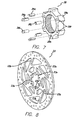
- FIG. 4 is an exploded view of particular embodiments of disc brake components associated with wheel hub 12.
- disc (or disk) brake rotor 23 is detachably and nonrotatably connected to disc brake hub 12 using an adapter 28, a fastener in the form of a lock ring 29, a washer 27 and a securing ring or rotor retaining member 30.
- Disc brake rotor 23, adapter 28, lock ring 29 and rotor retaining member 30 comprise a disc brake rotor assembly 8.
- rotor retaining member 30 couples disc brake rotor 23 to adapter 28 without requiring rivets, bolts or tools.
- Front disc brake hub 12 is nearly identical to the rear disc brake hub 12' except that it lacks a freewheel.
- disc brake hub 12 comprises a hub axle 31, a hub shell 32 rotatably supported on hub axle 31 in a conventional manner, a first spoke connecting flange 33a, a second spoke connecting flange 33b, and a brake rotor attachment unit 34.
- First and second spoke connecting flanges 33a and 33b and brake rotor attachment unit 34 are formed as a unified part with hub shell 32.
- First spoke connecting flange 33a is an annular spoke flange disposed on hub shell 32 at a first hub shell end 32a of hub shell 32.
- a plurality of first spoke openings 43a are formed circumferentially equidistant in first spoke connecting flange 33a for receiving the curved ends of each of a plurality of the spokes 24.
- second spoke connecting flange 33b is an annular spoke flange disposed on hub shell 32 at a second hub shell end 32b of hub shell 32.
- a plurality of second spoke openings 43b are formed circumferentially equidistant in second spoke connecting flange 33b for receiving the curved ends of each of another plurality of spokes 24.
- the spokes 24 extend radially outwardly in a circumferential manner.
- Brake rotor attachment unit 34 is disposed at first hub shell end 32a of hub shell 32 adjacent to first spoke connecting flange 33a.
- Brake rotor attachment unit 34 comprises a tubular member 34a and an annular adjoining flange 34b extending radially outwardly from tubular member 34a.
- Tubular member 34a has an outer peripheral surface defining a plurality of male splines 34c and an inner peripheral surface defining a female threaded portion 34d. It will be understood that the brake rotor attachment unit 34 is not a limitation on the present invention, and that any unit for coupling the hub 12 and adapter 28 is within the scope of the present invention.
- adapter 28 comprises a main body 28a that is generally annular in shape with a center opening 28b.
- the inner peripheral surface of center opening 28b defines a plurality of female splines 28c.
- Splines 28c are adapted to engage the plurality of splines 34c on brake rotor attachment unit 34 of hub 12 so that adapter 28 can be nonrotatably coupled to hub 12.
- Main body 28a includes a plurality of equally spaced rotor attachment arms 28e. Each rotor attachment arm 28e preferably includes at least one axially extending protruding portion 28d.
- Adapter 28 is preferably made of a rigid material, such as aluminum.
- adapter 28 has a plurality of openings 28f defined therein for receiving the protruding portions 28d.
- the openings 28f each include a key 28g extending axially that couples with a corresponding keyway 28h defined in each of the protruding portions 28d.
- the protruding portions 28d preferably each include a stepped portion 28i and have a groove 28j defined therein, as best shown in FIG. 16.
- the protruding portions 28d can be formed as a unit with the remainder of the adapter 28.
- protruding portions 28d may be welded to the main body 28a.
- Other ways of forming protruding portions on the main body portion will be readily apparent to those skilled in the art.
- disc brake rotor 23 comprises a braking ring 23a formed with a plurality of openings, a plurality of (e.g., eight) connecting arms 23b disposed circumferentially equidistant and extending radially inwardly from braking ring 23a, and an inner attachment unit 23c connected tangentially to the inner ends of the plurality of connecting arms 23b so that the plurality of connecting arms 23b form a plurality of triangular openings.
- braking ring 23a, the plurality of connecting arms 23b and inner attachment unit 23c are one piece.
- Disc brake rotor 23 preferably is made from stainless steel or some other appropriate material, usually with a specific gravity greater than that of the material forming adapter 28, that can withstand braking forces.
- Inner attachment unit 23c comprises a plurality of circumferentially equidistant connection openings 23d, preferably one per protruding portion 28d on adapter 28, a plurality of (e.g., six) circumferentially equidistant connection notches 23e.
- Each protruding portion 28d in adapter 28 engages a corresponding connection opening 23d in inner attachment unit 23c so that disc brake rotor 23 may be nonrotatably attached to adapter 28.
- the axial length of each protruding portion 28d is preferably long enough to extend through the connection opening 28d so that groove 28j is on the opposite side of disc brake rotor 28 that main body 28a of adapter 28 is.
- disc brake rotor 23 and that the components making up disc brake rotor 23 are not a limitation on the present invention.
- disc brake rotor 23 could be solid.
- rotor retaining member 30 is generally annular or ring shaped.
- rotor retaining member 30 comprises an elongated piece of metal or wire that is formed into a ring and includes a gap 30a between the opposite ends of the wire.
- the gap 30a allows the rotor retaining member 30 to be elastically deformable and sized so that it can fit into the grooves 28j in the protruding portions 28d.
- the rotor retaining member 30 does not have to be made of metal. Any substantially ring shaped member that can engage the protrusive portions 28d (preferably by fitting into the grooves 28j) is within the scope of the present invention.
- rotor retaining member 30 could be a rubber or plastic band.
- lock ring 29 comprises an annular flange 29c and a tubular portion 29d that extends axially from the inner peripheral surface of flange 29c.
- Flange 29c includes a central opening 29a partially defined by a plurality of female splines 29b that are adapted to engage an assembly tool (not shown).
- Tubular portion 29d includes a male threaded portion 29e structured to engage the female threaded portion 34d on brake rotor attachment unit 34 of hub 12.
- Side face of flange 29c includes a rotation inhibiting structure, which is preferably a plurality of serrations or ridges 29f that are adapted to engage a plurality of corresponding ridges 27a on a side face of washer 27.
- washer 27 includes a central opening 27b, ridges 27a (as described above) and a plurality of washer connection openings 27c defined therethrough.
- the washer connection openings 27c correspond to the connection openings 23d in the disc brake rotor 23 and the protruding portions 28d on the adapter 28.
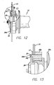
- FIGS. 12-15 show the disc brake rotor assembly 8 attached to hub 12.
- FIG. 13 is a detailed view showing how rotor retaining member 30 retains disc brake rotor 23 to adapter 28.
- adapter 28 is mounted to brake rotor attachment unit 34 of hub 12 by engaging the male splines 34c on brake rotor attachment unit 34 with the female splines 28c on adapter 28.
- disc brake rotor 23 is placed on adapter 28 by engaging protruding portions 28d of adapter 28 with the corresponding connection openings 23d in disc brake rotor 23.
- Washer 27 is then also placed on adapter 28 by engaging protruding portions 28d of adapter 28 with the corresponding washer connection openings 27c.
- Rotor retaining member 30 is then engaged with protruding portions 28d. Preferably, this is done by elastically deforming the rotor retaining member 30 and placing portions of the rotor retaining member 30 into each of the grooves 28j in the protruding portions 28d, as shown in FIG. 15.
- rotor retaining member 30 is elastically deformable because gap 30a prevents rotor retaining member 30 from forming a complete ring. This allows rotor retaining member 30 to be deformable radially outwardly by pulling the opposite ends of the ring apart at the gap 30a. Because of the elastic qualities of the material from which the rotor retaining member 30 is made, it snaps back into place once placed in the grooves 28j and released.
- disc brake rotor 23 is retained to adapter 28 simply by elastically deforming rotor retaining member 30 and placing portions of it into the grooves 28j in the protruding portions 28d of the adapter 28. Attaching and tightening bolts are not required, thus greatly simplifying the manufacturing operation and enhancing production efficiency.
- lock ring 29 is screwed into the female threaded portion 34d of brake rotor attachment unit 34 of hub 12 to tightly secure disc brake rotor assembly 8 to hub 12.
- the ridges 29f thereon engage the ridges on the washer 27.
- the washer can be omitted and the ridges can be defined in the disc brake rotor or the ridges can be omitted altogether.
- the disc brake rotor 23, sandwiched between adapter 28 and washer 27 and lock ring 29 to form a strong connection, is thereby secured in a non-rotatable state to the brake rotor attachment unit 34 of hub 12.
- lock ring 29 is unscrewed from the female threaded portion 34d of brake rotor attachment unit 34 of hub 12. Then, the rotor retaining member 30 is elastically deformed by pulling the opposite ends of the ring apart at the gap 30a, such that the rotor retaining member 30 is disengaged from the grooves 28j. Washer 27 and disc brake rotor 23 may then be removed from adapter 28, and adapter 28 may be removed from brake rotor attachment unit 34 of hub 12.
- FIG. 17 shows another preferred embodiment of the present invention.
- the adapter 28 and hub 50 are formed as an integral unit.
- This embodiment is similar to the embodiment described above, except that the brake rotor attachment unit 34 and its associated components are omitted because the adapter 28 is already part of the hub 50.
- the remainder of the components of the disc brake rotor assembly 8 (the lock ring 29, rotor retaining member 30 and washer 27) are assembled with the adapter 28 in the same manner as described above.
- the step of having to couple the adapter to the hub is omitted. This simplifies production and allows for a reduction in the number of separate components necessary to assembly the hub 50 and disc brake rotor assembly 8.
- the size, shape, location or orientation of the various components may be changed as desired. Components that are shown directly connected or contacting each other may have intermediate structures disposed between them. Those features that are designated as preferable certainly are not necessary. The functions of one element may be performed by two, and vice versa. The structures and functions of one embodiment may be adopted in another embodiment. It is not necessary for all advantages to be present in a particular embodiment at the same time. Every feature which is unique from the prior art, alone or in combination with other features, also should be considered a separate description of further inventions by the applicant, including the structural and/or functional concepts embodied by such feature(s). Thus, the scope of the invention should not be limited by the specific structures disclosed or the apparent initial focus or emphasis on a particular structure or feature.
Landscapes
- Engineering & Computer Science (AREA)
- Mechanical Engineering (AREA)
- General Engineering & Computer Science (AREA)
- Braking Arrangements (AREA)
Applications Claiming Priority (1)
| Application Number | Priority Date | Filing Date | Title |
|---|---|---|---|
| US11/406,476 US7665584B2 (en) | 2006-04-17 | 2006-04-17 | Disc rotor retaining assembly |
Publications (3)
| Publication Number | Publication Date |
|---|---|
| EP1847452A2 true EP1847452A2 (fr) | 2007-10-24 |
| EP1847452A3 EP1847452A3 (fr) | 2008-11-05 |
| EP1847452B1 EP1847452B1 (fr) | 2010-01-06 |
Family
ID=37533248
Family Applications (1)
| Application Number | Title | Priority Date | Filing Date |
|---|---|---|---|
| EP06255559A Not-in-force EP1847452B1 (fr) | 2006-04-17 | 2006-10-27 | Dispositif de fixation d'un rotor d'un frein à disque |
Country Status (3)
| Country | Link |
|---|---|
| US (1) | US7665584B2 (fr) |
| EP (1) | EP1847452B1 (fr) |
| DE (1) | DE602006011577D1 (fr) |
Cited By (5)
| Publication number | Priority date | Publication date | Assignee | Title |
|---|---|---|---|---|
| WO2012025604A1 (fr) * | 2010-08-26 | 2012-03-01 | Gustav Magenwirth Gmbh & Co. Kg | Instrument capteur et frein à disque hydraulique |
| CN103979058A (zh) * | 2014-05-26 | 2014-08-13 | 郑永华 | 一种碟刹的刹车盘装配方法 |
| IT201700046888A1 (it) * | 2017-05-02 | 2018-11-02 | Campagnolo Srl | Assieme di disco freno per bicicletta |
| WO2019158486A1 (fr) * | 2018-02-19 | 2019-08-22 | Renault S.A.S | Dispositif de freinage avec élément de pré-maintien d'un disque de frein sur un moyeu |
| US10480601B2 (en) | 2016-06-22 | 2019-11-19 | Sram, Llc | Heat dissipating brake rotor |
Families Citing this family (28)
| Publication number | Priority date | Publication date | Assignee | Title |
|---|---|---|---|---|
| EP2066578B1 (fr) * | 2006-09-14 | 2011-12-28 | Otis Elevator Company | Frein d'ascenseur à moyeu de frein composite |
| US8671949B2 (en) | 2009-06-23 | 2014-03-18 | 3M Innovative Properties Company | Headgear-earwear assembly and a method of assembling same |
| US11274717B2 (en) | 2010-07-02 | 2022-03-15 | Shimano Inc. | Brake rotor assembly |
| DE102010040045A1 (de) * | 2010-08-31 | 2012-03-01 | Gustav Magenwirth Gmbh & Co. Kg | Geberarmatur und hydraulische Scheibenbremse |
| DE102010035492A1 (de) * | 2010-08-26 | 2012-03-01 | Gustav Magenwirth Gmbh & Co. Kg | Hydraulische Scheibenbremse |
| US8186698B2 (en) * | 2010-10-27 | 2012-05-29 | Gunderson Mark E | Tricycle |
| TW201233919A (en) * | 2011-02-15 | 2012-08-16 | William B Shook | Bicycle and ring thereof |
| US20130240309A1 (en) * | 2011-10-13 | 2013-09-19 | Wayne-Ian Moore | Brake Disk Assembly |
| US9878577B2 (en) * | 2013-09-12 | 2018-01-30 | Walther Engineering And Manufacturing Company, Inc. | Hub-rotor adapter |
| US9334910B2 (en) * | 2014-05-28 | 2016-05-10 | Shimano Inc. | Lock member for fixedly locking a disc brake rotor on a bicycle hub |
| USD749477S1 (en) * | 2014-12-17 | 2016-02-16 | Sram, Llc | Disc brake rotor portion |
| USD749025S1 (en) * | 2014-12-17 | 2016-02-09 | Sram, Llc | Disc brake rotor portion |
| USD749476S1 (en) * | 2014-12-17 | 2016-02-16 | Sram, Llc | Disc brake rotor portion |
| TWI549854B (zh) * | 2015-05-28 | 2016-09-21 | Bicycle rear wheel quick release structure | |
| US10215245B2 (en) | 2015-09-16 | 2019-02-26 | Performance Friction Corporation | Floating rotor disc with compressible retention ring fastener |
| IT201600069575A1 (it) * | 2016-07-05 | 2018-01-05 | Campagnolo Srl | Disco freno per bicicletta |
| IT201600069580A1 (it) | 2016-07-05 | 2018-01-05 | Campagnolo Srl | Disco freno per bicicletta |
| US10995806B2 (en) | 2017-07-26 | 2021-05-04 | Dt Swiss Inc. | Hub, in particular for bicycles |
| DE102017116960A1 (de) * | 2016-07-26 | 2018-02-01 | Dt Swiss Ag | Nabe insbesondere für Fahrräder |
| CN117703964A (zh) | 2017-01-13 | 2024-03-15 | 株式会社岛野 | 盘式制动器转子 |
| US10919339B2 (en) * | 2017-05-22 | 2021-02-16 | Shimano Inc. | Bicycle hub assembly and bicycle drive train assembly |
| CN109695645B (zh) * | 2017-10-24 | 2024-03-05 | 广东洛梵狄智能科技有限公司 | 一种轮毂制动组件 |
| US10704628B2 (en) | 2018-07-20 | 2020-07-07 | Bendix Spicer Foundation Brake Llc | Brake disc mounting arrangement |
| US10830295B2 (en) | 2018-07-20 | 2020-11-10 | Bendix Spicer Foundation Brake Llc | Brake disc mounting arrangement |
| US10837509B2 (en) * | 2018-07-20 | 2020-11-17 | Bendix Spicer Foundation Brake Llc | Brake disc mounting arrangement |
| US12403981B2 (en) * | 2022-03-28 | 2025-09-02 | Trickstuff Gmbh | Wheel component with a fixing ring for attaching a brake disk device to a bicycle hub |
| WO2024103170A1 (fr) * | 2022-11-15 | 2024-05-23 | 2360216 Ontario Inc | Ensemble adaptateur de frein à disque |
| DE102024208259A1 (de) * | 2024-08-30 | 2026-03-05 | Shimano Inc. | Komponente für ein menschlich angetriebenes fahrzeug |
Family Cites Families (17)
| Publication number | Priority date | Publication date | Assignee | Title |
|---|---|---|---|---|
| US3542166A (en) * | 1967-11-09 | 1970-11-24 | Girling Ltd | Brake disc and supporting means therefor |
| JPS61241538A (ja) * | 1985-04-19 | 1986-10-27 | Yamaha Motor Co Ltd | フロ−ト型制動デイスクの支持構造 |
| JPS63280937A (ja) * | 1987-05-12 | 1988-11-17 | Aisin Chem Co Ltd | 摩擦部材 |
| IT1271250B (it) * | 1994-10-07 | 1997-05-27 | Freni Brembo Spa | Disco di un freno a disco autoventilato |
| FR2783491B1 (fr) | 1998-09-17 | 2000-12-15 | Mavic Sa | Frein a disque a commande mecanique pour bicyclette et roue equipe d'un tel frein a disque |
| DE69836212D1 (de) * | 1998-09-17 | 2006-11-30 | Freni Brembo Spa | Scheibe für eine Scheibenbremse |
| US6540306B2 (en) * | 2001-06-29 | 2003-04-01 | Shimano Inc. | Bicycle disc brake hub |
| US6371252B1 (en) | 2001-08-30 | 2002-04-16 | Shimano Inc. | Bicycle disc brake hub |
| WO2003100281A1 (fr) * | 2002-05-27 | 2003-12-04 | Yutaka Giken Co., Ltd. | Disque de frein de type flottant |
| US6854569B2 (en) * | 2003-03-18 | 2005-02-15 | Kun Teng Industry Co., Ltd. | Brakable wheel hub device |
| WO2004088162A1 (fr) * | 2003-03-28 | 2004-10-14 | Hayes Disc Brakes, Llc | Rotor de frein a disque a montage rapide |
| JP2005188703A (ja) * | 2003-12-26 | 2005-07-14 | Shimano Inc | ディスクブレーキロータアセンブリ |
| JP2005188704A (ja) * | 2003-12-26 | 2005-07-14 | Shimano Inc | ディスクブレーキロータアセンブリ |
| EP1634725A1 (fr) | 2004-09-10 | 2006-03-15 | Kun Teng Industry Co., Ltd. | Dispositif de moyeu de roue freinable |
| DE202004016158U1 (de) | 2004-10-19 | 2005-02-24 | Kun Teng Industry Co., Ltd., Ta-Ya Hsiang | Bremsbare Radnabenvorrichtung |
| DE202005009504U1 (de) | 2005-06-17 | 2005-11-03 | Kun Teng Industry Co., Ltd., Ta-Ya Hsiang | Bremsbare Radnabenvorrichtung |
| DE202006000549U1 (de) | 2006-01-14 | 2006-03-09 | Ming Cycle Industrial CO., LTD., Taiping | Nabenanordnung für eine Scheibenbremse eines Fahrrades |
-
2006
- 2006-04-17 US US11/406,476 patent/US7665584B2/en not_active Expired - Fee Related
- 2006-10-27 DE DE602006011577T patent/DE602006011577D1/de active Active
- 2006-10-27 EP EP06255559A patent/EP1847452B1/fr not_active Not-in-force
Cited By (11)
| Publication number | Priority date | Publication date | Assignee | Title |
|---|---|---|---|---|
| WO2012025604A1 (fr) * | 2010-08-26 | 2012-03-01 | Gustav Magenwirth Gmbh & Co. Kg | Instrument capteur et frein à disque hydraulique |
| EP3150879A1 (fr) * | 2010-08-26 | 2017-04-05 | Gustav Magenwirth GmbH & Co. KG | Frein à disque hydraulique |
| CN103979058A (zh) * | 2014-05-26 | 2014-08-13 | 郑永华 | 一种碟刹的刹车盘装配方法 |
| CN103979058B (zh) * | 2014-05-26 | 2016-05-04 | 郑永华 | 一种碟刹的刹车盘装配方法 |
| US10480601B2 (en) | 2016-06-22 | 2019-11-19 | Sram, Llc | Heat dissipating brake rotor |
| IT201700046888A1 (it) * | 2017-05-02 | 2018-11-02 | Campagnolo Srl | Assieme di disco freno per bicicletta |
| EP3399206A1 (fr) * | 2017-05-02 | 2018-11-07 | Campagnolo S.r.l. | Ensemble de disque de frein de bicyclette |
| CN108799361A (zh) * | 2017-05-02 | 2018-11-13 | 坎培诺洛有限公司 | 自行车制动盘组件 |
| US10753412B2 (en) | 2017-05-02 | 2020-08-25 | Campagnolo S.R.L. | Bicycle brake disc assembly |
| WO2019158486A1 (fr) * | 2018-02-19 | 2019-08-22 | Renault S.A.S | Dispositif de freinage avec élément de pré-maintien d'un disque de frein sur un moyeu |
| FR3078123A1 (fr) * | 2018-02-19 | 2019-08-23 | Renault S.A.S | Dispositif de freinage avec element de pre-maintien d’un disque de frein sur un moyeu |
Also Published As
| Publication number | Publication date |
|---|---|
| EP1847452A3 (fr) | 2008-11-05 |
| DE602006011577D1 (de) | 2010-02-25 |
| US20070240945A1 (en) | 2007-10-18 |
| EP1847452B1 (fr) | 2010-01-06 |
| US7665584B2 (en) | 2010-02-23 |
Similar Documents
| Publication | Publication Date | Title |
|---|---|---|
| EP1847452B1 (fr) | Dispositif de fixation d'un rotor d'un frein à disque | |
| EP1548318B1 (fr) | Appareil pour retenir un rotor de frein à disque de bicyclette sur un moyeu de roue de bicyclette. | |
| US7143872B2 (en) | Apparatus for retaining a bicycle disk brake rotor to a bicycle wheel hub | |
| US6371252B1 (en) | Bicycle disc brake hub | |
| US5626401A (en) | Spoked wheel hub | |
| US7216743B2 (en) | Bicycle disc brake rotor assembly | |
| US6523659B2 (en) | Bicycle hub with tight connection ratchet and detachable freewheel | |
| US9944119B2 (en) | Hub assembly for a bicycle | |
| TW553855B (en) | Bicycle hub with threaded spacer and detachable freewheel | |
| US6886894B2 (en) | Bicycle hub axle | |
| CZ20014361A3 (cs) | Hlava kola bicyklu s kluznou spojovací součástí a oddělitelnou volnoběžkou | |
| JP3619458B2 (ja) | ディスクブレーキ用自転車ハブ | |
| TW436430B (en) | Hub shell for bicycle | |
| JP3703781B2 (ja) | 自転車用ディスクブレーキハブ | |
| EP1122097A2 (fr) | Moyeu de bicyclette pour rayons tangentielles | |
| US20030219303A1 (en) | Locking member for bicycle component | |
| CN205044904U (zh) | 用于自行车部件的锁定构件 | |
| US6485108B1 (en) | Bicycle hub | |
| WO2009000011A1 (fr) | Système de transmission pour un vélo | |
| CN223865056U (zh) | 一种压铆式的锁碟片 | |
| CN117858807A (zh) | 用于电动助力自行车的轮单元和电动助力自行车 |
Legal Events
| Date | Code | Title | Description |
|---|---|---|---|
| PUAI | Public reference made under article 153(3) epc to a published international application that has entered the european phase |
Free format text: ORIGINAL CODE: 0009012 |
|
| AK | Designated contracting states |
Kind code of ref document: A2 Designated state(s): AT BE BG CH CY CZ DE DK EE ES FI FR GB GR HU IE IS IT LI LT LU LV MC NL PL PT RO SE SI SK TR |
|
| AX | Request for extension of the european patent |
Extension state: AL BA HR MK YU |
|
| PUAL | Search report despatched |
Free format text: ORIGINAL CODE: 0009013 |
|
| AK | Designated contracting states |
Kind code of ref document: A3 Designated state(s): AT BE BG CH CY CZ DE DK EE ES FI FR GB GR HU IE IS IT LI LT LU LV MC NL PL PT RO SE SI SK TR |
|
| AX | Request for extension of the european patent |
Extension state: AL BA HR MK RS |
|
| RIC1 | Information provided on ipc code assigned before grant |
Ipc: B60B 27/02 20060101ALI20080926BHEP Ipc: B62L 1/00 20060101AFI20061227BHEP Ipc: F16D 65/12 20060101ALI20080926BHEP |
|
| 17P | Request for examination filed |
Effective date: 20081110 |
|
| 17Q | First examination report despatched |
Effective date: 20081211 |
|
| AKX | Designation fees paid |
Designated state(s): DE NL |
|
| GRAP | Despatch of communication of intention to grant a patent |
Free format text: ORIGINAL CODE: EPIDOSNIGR1 |
|
| GRAS | Grant fee paid |
Free format text: ORIGINAL CODE: EPIDOSNIGR3 |
|
| GRAA | (expected) grant |
Free format text: ORIGINAL CODE: 0009210 |
|
| AK | Designated contracting states |
Kind code of ref document: B1 Designated state(s): DE NL |
|
| REF | Corresponds to: |
Ref document number: 602006011577 Country of ref document: DE Date of ref document: 20100225 Kind code of ref document: P |
|
| REG | Reference to a national code |
Ref country code: NL Ref legal event code: T3 |
|
| PLBE | No opposition filed within time limit |
Free format text: ORIGINAL CODE: 0009261 |
|
| STAA | Information on the status of an ep patent application or granted ep patent |
Free format text: STATUS: NO OPPOSITION FILED WITHIN TIME LIMIT |
|
| 26N | No opposition filed |
Effective date: 20101007 |
|
| PGFP | Annual fee paid to national office [announced via postgrant information from national office to epo] |
Ref country code: NL Payment date: 20111020 Year of fee payment: 6 |
|
| REG | Reference to a national code |
Ref country code: NL Ref legal event code: V1 Effective date: 20130501 |
|
| PG25 | Lapsed in a contracting state [announced via postgrant information from national office to epo] |
Ref country code: NL Free format text: LAPSE BECAUSE OF NON-PAYMENT OF DUE FEES Effective date: 20130501 |
|
| PGFP | Annual fee paid to national office [announced via postgrant information from national office to epo] |
Ref country code: DE Payment date: 20181016 Year of fee payment: 13 |
|
| REG | Reference to a national code |
Ref country code: DE Ref legal event code: R119 Ref document number: 602006011577 Country of ref document: DE |
|
| PG25 | Lapsed in a contracting state [announced via postgrant information from national office to epo] |
Ref country code: DE Free format text: LAPSE BECAUSE OF NON-PAYMENT OF DUE FEES Effective date: 20200501 |