EP1847470A2 - Fermeture pour un récipient - Google Patents
Fermeture pour un récipient Download PDFInfo
- Publication number
- EP1847470A2 EP1847470A2 EP07007716A EP07007716A EP1847470A2 EP 1847470 A2 EP1847470 A2 EP 1847470A2 EP 07007716 A EP07007716 A EP 07007716A EP 07007716 A EP07007716 A EP 07007716A EP 1847470 A2 EP1847470 A2 EP 1847470A2
- Authority
- EP
- European Patent Office
- Prior art keywords
- guide
- closure
- closure according
- outlet opening
- hinged lid
- Prior art date
- Legal status (The legal status is an assumption and is not a legal conclusion. Google has not performed a legal analysis and makes no representation as to the accuracy of the status listed.)
- Granted
Links
Images


Classifications
-
- B—PERFORMING OPERATIONS; TRANSPORTING
- B65—CONVEYING; PACKING; STORING; HANDLING THIN OR FILAMENTARY MATERIAL
- B65D—CONTAINERS FOR STORAGE OR TRANSPORT OF ARTICLES OR MATERIALS, e.g. BAGS, BARRELS, BOTTLES, BOXES, CANS, CARTONS, CRATES, DRUMS, JARS, TANKS, HOPPERS, FORWARDING CONTAINERS; ACCESSORIES, CLOSURES, OR FITTINGS THEREFOR; PACKAGING ELEMENTS; PACKAGES
- B65D51/00—Closures not otherwise provided for
- B65D51/18—Arrangements of closures with protective outer cap-like covers or of two or more co-operating closures
- B65D51/20—Caps, lids, or covers co-operating with an inner closure arranged to be opened by piercing, cutting, or tearing
- B65D51/22—Caps, lids, or covers co-operating with an inner closure arranged to be opened by piercing, cutting, or tearing having means for piercing, cutting, or tearing the inner closure
- B65D51/221—Caps, lids, or covers co-operating with an inner closure arranged to be opened by piercing, cutting, or tearing having means for piercing, cutting, or tearing the inner closure a major part of the inner closure being left inside the container after the opening
- B65D51/222—Caps, lids, or covers co-operating with an inner closure arranged to be opened by piercing, cutting, or tearing having means for piercing, cutting, or tearing the inner closure a major part of the inner closure being left inside the container after the opening the piercing or cutting means being integral with, or fixedly attached to, the outer closure
- B65D51/225—Caps, lids, or covers co-operating with an inner closure arranged to be opened by piercing, cutting, or tearing having means for piercing, cutting, or tearing the inner closure a major part of the inner closure being left inside the container after the opening the piercing or cutting means being integral with, or fixedly attached to, the outer closure and further comprising a device first inhibiting displacement of the outer closure
-
- B—PERFORMING OPERATIONS; TRANSPORTING
- B65—CONVEYING; PACKING; STORING; HANDLING THIN OR FILAMENTARY MATERIAL
- B65D—CONTAINERS FOR STORAGE OR TRANSPORT OF ARTICLES OR MATERIALS, e.g. BAGS, BARRELS, BOTTLES, BOXES, CANS, CARTONS, CRATES, DRUMS, JARS, TANKS, HOPPERS, FORWARDING CONTAINERS; ACCESSORIES, CLOSURES, OR FITTINGS THEREFOR; PACKAGING ELEMENTS; PACKAGES
- B65D47/00—Closures with filling and discharging, or with discharging, devices
- B65D47/04—Closures with discharging devices other than pumps
- B65D47/06—Closures with discharging devices other than pumps with pouring spouts or tubes; with discharge nozzles or passages
- B65D47/08—Closures with discharging devices other than pumps with pouring spouts or tubes; with discharge nozzles or passages having articulated or hinged closures
- B65D47/0804—Closures with discharging devices other than pumps with pouring spouts or tubes; with discharge nozzles or passages having articulated or hinged closures integrally formed with the base element provided with the spout or discharge passage
- B65D47/0809—Closures with discharging devices other than pumps with pouring spouts or tubes; with discharge nozzles or passages having articulated or hinged closures integrally formed with the base element provided with the spout or discharge passage and elastically biased towards both the open and the closed positions
-
- B—PERFORMING OPERATIONS; TRANSPORTING
- B65—CONVEYING; PACKING; STORING; HANDLING THIN OR FILAMENTARY MATERIAL
- B65D—CONTAINERS FOR STORAGE OR TRANSPORT OF ARTICLES OR MATERIALS, e.g. BAGS, BARRELS, BOTTLES, BOXES, CANS, CARTONS, CRATES, DRUMS, JARS, TANKS, HOPPERS, FORWARDING CONTAINERS; ACCESSORIES, CLOSURES, OR FITTINGS THEREFOR; PACKAGING ELEMENTS; PACKAGES
- B65D2251/00—Details relating to container closures
- B65D2251/0003—Two or more closures
- B65D2251/0006—Upper closure
- B65D2251/0025—Upper closure of the 47-type
-
- B—PERFORMING OPERATIONS; TRANSPORTING
- B65—CONVEYING; PACKING; STORING; HANDLING THIN OR FILAMENTARY MATERIAL
- B65D—CONTAINERS FOR STORAGE OR TRANSPORT OF ARTICLES OR MATERIALS, e.g. BAGS, BARRELS, BOTTLES, BOXES, CANS, CARTONS, CRATES, DRUMS, JARS, TANKS, HOPPERS, FORWARDING CONTAINERS; ACCESSORIES, CLOSURES, OR FITTINGS THEREFOR; PACKAGING ELEMENTS; PACKAGES
- B65D2251/00—Details relating to container closures
- B65D2251/0003—Two or more closures
- B65D2251/0068—Lower closure
- B65D2251/0093—Membrane
Definitions
- the invention relates to a closure for a container, in particular a tube, wherein the container has an outlet opening, which is sealed in a delivery state with a designed as a predetermined breaking point sealing element, in particular a membrane, wherein the closure is a lower part, which is connected to the container , a passage opening and an upper part, which is connectable to the lower part comprises.
- Containers with a sealed outlet port are used, for example, in the cosmetics industry, the pharmaceutical industry or the food industry for packaging products which require particularly safe and possibly detectable product protection, such as, for example, personal care and sun creams or oils.
- product protection such as, for example, personal care and sun creams or oils.
- medicinal ointments and lotions but also for liquid or pasty foods, such as mayonnaise, mustard or ketchup, as well as other fluid or pasty substances.
- a particularly reliable product protection is in the construction of such containers z.
- B. achieved by the use of aluminum foils, usually in combination with materials such as plastic or paper in a composite.
- aluminum is used in aluminum or aluminum laminate tubes.
- the sealing elements of such containers are often foils which are mounted over the outlet opening and in particular often have aluminum foils or are made entirely of aluminum.
- sealing membranes have the consequence that they are susceptible to damage.
- the closure reliably protect the sealing element from manufacture to first use on the part of the consumer, in particular during transport.
- the piercing spike is arranged on the inside of the closure cap and is only applied to the container neck to the extent that the tip of the piercing spike is spaced from the membrane during production of the delivery condition. Once the closure is completely applied, the membrane is pierced by the piercing spike, whereby the use state is established.
- a removable spacer ring is used, which is mounted between the container shoulder and the underside of the cap and the full application of the cap initially prevents existing spacer ring.
- the spacer ring is obtained by the removal as a waste product. Moreover, it is disadvantageous that the removal of the spacer ring requires a certain manual skill of the consumer, which can not be assumed in many people.
- the disadvantage here is that the overcoming of the locking connection results in a jerky movement of the closure cap towards the container, which is stopped by the meeting of the internal thread of the cap on the external thread of the container neck.
- a repeated jerky approach of the two threads can damage them permanently, so that a reliable closure of the container may no longer be possible.
- Object of the present invention is to provide a closure for a container and a container, which eliminate the disadvantages described and are safe and also comfortable to handle.
- an auxiliary device is provided for opening the sealed outlet opening of the container, which is assigned to the upper part and which can be guided by a guide means from a first to a second position, whereby a force can be applied to the sealing element, which sealed outlet opening opens.
- the container is a tube, in particular an aluminum tube or a tube made of aluminum laminate.
- the container is preferably provided with a designed as a predetermined breaking point sealing element, which may be a membrane.
- the sealing element may be formed by an aluminum wall of small thickness, or may comprise an aluminum foil or a foil of aluminum laminate.
- the container preferably has a container neck, which is arranged coaxially to an axis of the container on an outer side of the container. But it is also possible that no Be fiscalnishals is provided.
- the container preferably has latching means, by means of which the lower part can be secured by a latching connection to the container.
- These locking means preferably have a substantially annular bead, which surrounds the container neck and is preferably arranged close to the container, so that between the bead and the container, a substantially annular Umlaufsnut is formed.
- the lower part of the closure is a substantially hollow cylinder-like body, which preferably has latching means for a latching connection with the container.
- These locking means are preferably formed at its lower end on its inner side as a circumferential projection and a circumferential groove arranged above it so that the peripheral projection of the lower part can engage in the Umlaufsnut on the container and at the same time engage the peripheral bead on the container in the circumferential groove on the lower part can.
- the lower part can be reliably connected by means of the locking connection described with the container.
- the lower part is attached to the container by another type of locking connection, that it is fastened by an adhesive connection to the container or that a further type of connection is provided.
- the guide device of the closure according to the invention preferably has at least one groove-like guide, which is preferably arranged on the outside of the lower part. But it is also possible that this guide is arranged on the inside of the upper part. In particular, at least three such guides can be provided.
- the inventive design of this guide allows the guide of the upper part and the auxiliary device associated therewith from a first to a second position.
- the guide device has at least one projection which is preferably arranged on the inside of the upper part and which is designed for positive engagement in this guide and is guided in a movement of the upper part connected to the upper part in the guide.
- the projection is provided on the outside of the lower part. In particular, at least three such projections may be provided.
- three groove-like guides are provided on the outside of the lower part.
- three projections are preferably provided on the inside of the upper part, by means of which the upper part moves according to the guide profile, i. can be performed.
- the groove-like guide is preferably formed by two mutually parallel walls, which rise from the outer wall of the lower part.
- the guide is formed as a recess in the outside of the lower part.
- the guide extends substantially from the upper end of the lower part along its guide line to the lower end of the lower part. Accordingly, the guide has an upper end, which is preferably substantially open, and also has a lower end, which is preferably closed by an end wall.
- the guide starting from its upper end, preferably has a first guide area, which in the essentially perpendicular to the container pointing downward. Following this first guide region, the guide preferably has a second guide region, which lies substantially in a horizontal plane and runs counter to the closure direction of the closure, ie, preferably counterclockwise as viewed from above, along the outside of the lower part. This horizontal plane is preferably located approximately halfway up the lower part. This second guidance area is followed by a third guidance area.
- This third guide region preferably begins approximately at the middle height of the lower part and then runs in the direction of the lower end of the lower part, preferably in the closing direction of the closure, ie seen from above in the clockwise direction. This results in a winding course of the third guide portion of the guide.
- An advantage of the design according to the invention of this guide profile is that a comparatively complex course of the movement of the upper part can be predetermined by the comparatively complex course of the guide. So it is also possible that the leadership has other or more leadership areas, resulting in a different leadership.
- the above-described design of the guide with a first, a second and a third guide region has the advantage according to the invention that two positions of the upper part and its associated auxiliary device can be defined.
- the auxiliary device In the first position, the auxiliary device is arranged such that its lower end is close to the sealing element of the outlet opening of the container.
- the projection In this first position, the projection is in a first position within the guide formed by the transition region of the first guide portion and the second guide portion of the guide.
- the upper part In this first position of the projection, the upper part can preferably be moved substantially only upwards or against the closing direction.
- the sealing element is accidentally broken by the auxiliary device by applying a force directed perpendicularly to the top of the upper part, as may be the case, in particular in a shock load, which occur for example in a fall of the container could.
- a shock load which occur for example in a fall of the container could.
- the greater compared to a conventional thread depth of the guide results in a higher load capacity against such impact load.
- the second position is the position in which the auxiliary device is arranged completely passing through the plane of the outlet opening of the container.
- the projection In this second position, the projection is in a second position, which is located at the lower end of the third guide region.
- the projection is preferably substantially opposite only to the direction of closure, i. seen from above counter-clockwise movable.
- the projection in this second position can be locked by suitable means. As a result, the upper part can be locked in this second position.
- the projection moves along the second guide region, in which it performs a substantially rotational movement.
- the projection performs a movement which is essentially translatory and rotational at the same time.
- the guide may have further means for influencing the mobility of the projection within the guide. It is provided that the guide preferably has at least one constriction in which the guide channel is narrowed by the thickening of at least one inner wall, whereby the accidental passage of the projection through the constriction is less likely, such a passage but by applying a force, in particular an intended Movement of the upper part is possible.
- such a narrowing point is provided in the first guide region of the guide and also provided in the second guide region of the guide, so that a locking of the projection in the first position can result.
- the advantage of this locking is that inertial forces, e.g. can occur during transport of a container provided with the closure, preferably does not lead to an unintentional change in the position of the upper part and in particular not to a detachment of the upper part connected to the lower part.
- such a constriction point is provided for locking the projection in the second position.
- At least one stop element is preferably provided, which is formed on the bottom of the guide groove as a threshold.
- the height of this threshold is less than the height of the inner wall of the guide, whereby the unintentional transfer of the projection to a position beyond the stubble is less likely, such a transfer but by applying a force, in particular by an intended movement of the upper part is possible.
- such a stop member may be disposed at the upper end of the guide to prevent inadvertent separation of the top from the base, as e.g. can be caused by transport inertial forces or slight impact forces can be prevented.
- the guide is formed as a puncture channel, which is provided as a recess in the outside of the lower part.
- the lower part of this is formed by a substantially hollow cylinder-like element, on whose outer wall at least one guide is arranged and which has for attachment to the container by means of a latching connection preferably at its lower end latching means.
- a latching connection preferably at its lower end latching means.
- the lower part is designed on its inner side such that the container neck positively engages in the lower part.
- the lower part has two hollow-cylindrical parts in a coaxial arrangement, which are preferably interconnected at its upper end by an annular connecting web, wherein an outer hollow cylinder-like part is provided, on the outer wall of which at least one guide is arranged and an inner hollow cylinder-like Part is provided which forms the passage opening and which preferably has at its lower end latching means for attachment to the container by means of a latching connection.
- the upper part is designed essentially as a lid, which has a lid end wall and a lid peripheral wall. It is possible that the lid peripheral wall to improve the handling of the lid has a structuring by depressions and / or elevations on the Cover peripheral wall may be formed.
- the cover end wall is preferably substantially planar, but may also be designed differently and in particular funnel-shaped and, in addition, may be designed in particular for the suitable arrangement of the auxiliary device.
- the auxiliary device is preferably a pin, in particular preferably a hollow pin, which is preferably arranged coaxially on the inside of the upper end side of the upper part.
- the lower end of the auxiliary device preferably has a tapered shape, and may be formed in particular conical. It is provided that the outer diameter is at most as large as the inner diameter of the outlet opening of the container.
- the upper part is designed as a hinged closure cap.
- the cap shows essentially the features of the DE 198 32 799 B4 described cap and is described by means of embodiments in the figures.
- Figure 1 shows a side cross-sectional view of the lower part with the container neck of the closure according to the invention according to embodiment 1.
- the embodiment 1 uses the lower part 101 according to its second embodiment.
- the lower part 101 has a passage opening 134 and two hollow cylindrical parts, i. H. an inner hollow cylinder 102 and an outer hollow cylinder 103, which are connected in coaxial arrangement with the axis 105 at its upper side by an annular connecting web 106 with each other.
- the inner hollow cylinder 102 is designed on its inside for the positive engagement of the container neck 108.
- the container neck 108 and the inner hollow cylinder 102 of the lower part have latching means which enable a latching connection of the lower part 101 to the container neck 108.
- These locking means consist in the embodiment 1 of a circumferential groove 110 which is provided at the lower end of the container neck 108 and the container neck circumferential bead 111. Furthermore, these locking means consist of a locking projection 112 which rotates on the inside at the bottom of the inner hollow cylinder 102 and an inner circumferential groove 113, which is disposed on the inside thereof over the locking projection 112 and also rotates in the inner hollow cylinder 102.
- the locking connection indicated in the drawing comes about in that the locking projection 112 engages in the circumferential groove 110 and the bead 111 in the inner circumferential groove 113.
- the wall of the inner hollow cylinder may be formed at least in its lower portion by downwardly facing tongues, preferably at the lower edge of these tongues described latching means, ie a latching projection 112 and an inner circumferential groove 113 may be provided.
- These tongues are in the lower area in the radial direction outwardly compared to a closed hollow cylinder wall relatively easily deflected elastically, whereby a conventional injection molding material can be used for the production of the lower part.
- the material of the inner hollow cylinder is chosen so soft that on the one hand, the production of the locking connection possible and on the other hand, the locking connection is stable.
- the guide 115 is located on the outside of the outer hollow cylinder 103 with a guide profile, as shown in FIG.
- the guide 115 consists essentially of two mutually parallel guide walls, which rise vertically from the surface outside of the outer hollow cylinder 103.
- the lower end is preferably closed by a closure wall 116.
- a stop member 117 which is formed as a threshold at the bottom of the guide groove.
- the height of this stop element is preferably made smaller than the height of a guide wall. It is envisaged that, depending on the height of the stop element, a certain force is necessary to move the projection over the stop element away from the guide and thus to remove the upper part from the lower part.
- the height of the stop element is designed such that the upper part provided with the projections can be attached to the lower part by an increased force without damaging the closure, which may be the case in particular during the mechanical assembly of the closure for producing the delivery state.
- the upper edge guide 118 which can serve as a guide for threading the projections into the guides in particular when omitting the Stoppelements 117.
- stop member 117 In addition to the stop member 117 are to control the mobility of the projection in the guide and constrictions 119 in the Guiding provided, which are preferably formed by a thickened portion of the inside of one or both guide walls. In this way, in particular a first position 125 and a second position 126 of the projection can be defined in the guide.
- the first position 125 of the projection is the position in which the auxiliary device for opening the sealing element is close to the sealing element, but this preferably still not touched.
- the second position 126 of the projection is the position in which the auxiliary device has completely passed through the sealing element and the outlet opening is thus opened.
- the upper part In order to be able to pierce the sealing element, in the exemplary embodiment shown in FIG. 1, the upper part must first be moved in the counterclockwise direction, before it can then, in a clockwise direction, pierce the sealing element with its auxiliary device. This will be explained with reference to the embodiment 2 shown in Fig. 2.
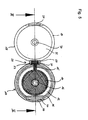
- FIG. 2 shows a schematic drawing of the guide of the closure according to the invention according to embodiment 2.
- the lower part 101 has in the embodiment 2 a guide with a first guide portion 131, a second guide portion 132 and a third guide portion 133.
- the projection can perform essentially only a translatory movement.
- This translational movement when using a closure designed according to embodiment 2, in connection with the movement of the upper part in the closure direction blocked in the first position 125 of the protrusion, can make clear to the consumer that, by placing the upper part on the lower part, the joining the two parts is still incomplete.
- a restriction 119 in the first guide area can serve to prevent inadvertent removal of the upper part from the lower part in the delivery state of the closure, in which the projection is preferably in the first position 125, by inertial forces or light impact loads, as z. B. may occur during transport of the container provided with the closure to prevent.
- the constrictions 119 have a signal effect on the consumer, since their overcoming requires a perceptible application of force.
- the change between the two positions 125 and 126 of the projection is thereby signaled, which in turn makes an accidental puncture of the sealing element less likely.
- the closure according to the invention therefore becomes even safer due to the constrictions 119.
- a simultaneous translational and rotational movement of the projection in the guide 115 and the upper part with respect to the lower part leads to the position 126 of the projection, the auxiliary device pierces the sealing element and opens the outlet opening of the container.
- the constriction 119 near the protrusion 126 position helps to hold the top in communication with the base, regardless of inertial forces and light impact forces that can act on the top, thereby making the operation of the closure more reliable. But it is also z. B. by a corresponding dimensioning of the parts possible that the upper part is held by a clamping connection between the projection, guide, the inside of the upper end face of the upper part and the upper side of the lower part on the lower part.
- an upper edge guide 118 runs substantially parallel to the upper edge, wherein the upper edge guide 118, in particular in the illustrated embodiment with a rounded and flowing transition into the guide 115 can simplify the threading of the projections into the guides.
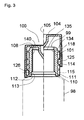
- FIG. 3 shows a lateral cross-sectional view of a container with the closure according to the invention, in particular in its first and its second position, according to embodiment 3.
- the embodiment 3 has a container 98 with a container neck 108 and an outlet opening 99 and the closure 100, the one Lower part 101 and an upper part 104 which are arranged substantially coaxially with axis 105.
- the upper part has on its inner peripheral side projections 114 for engagement in the guides 115 of the lower part 101.
- the lower part 101 corresponds in the embodiment 3 of the first embodiment of the lower part of the closure according to the invention and is essentially a hollow cylinder-like part.
- the upper part and the auxiliary device are shown in their first position to the right of the axis 105, in which the projection is in its first position 125.
- the upper part and the auxiliary device are shown in their second position, in which the projection is in its second position 126.
- the auxiliary device 140 In the first position, the auxiliary device 140 is located with its lower end near the position 135 of the sealing member, but this preferably still does not touch. In the second position, the auxiliary 135 passes completely through the position 135 of the sealing element.
- “Complete” in this context means that in the manner provided for by the construction of the closure according to the invention, the sealing element has passed through the sealing element in which a sufficient opening of the sealing element has taken place and does not necessarily mean that the complete volume of the auxiliary device through the sealing element has entered. It is easy to see that it is also possible that the sealing element is attached to the container after connection of the lower part in particular at least partially on the lower part or even completely on the lower part instead of the container.
- the auxiliary device 140 is formed in the embodiment 3 as a substantially hollow cylinder-like pin which tapers conically downwards and has a tip 141 which assists the piercing of the sealing element. But it is also possible that the lower end of the auxiliary device has a different shape than that provided in the embodiment 3 cone point by z. B. has multiple or no tips or projections.
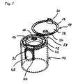
- FIG. 4 shows an embodiment of the upper part of the closure according to the invention designed as a closure cap in a schematic perspective view.
- the two embodiments of the closure caps each have a closure cap body 10 with a substantially cylindrical shape and a circular cross-section.
- a hollow cylinder 13 with projections 114, which are arranged on the inner wall, is preferably integrally connected to the underside of the upper boundary wall 12 of the closure cap body 10 and ensures a connection between the lower part 101 and the upper part 104.
- This hollow cylinder 13 is referred to below as a guide wall.
- a round hinged lid 18 is hingedly hinged by means of a hinge connection 28.
- the hinged lid 18 is shown in the open position in FIGS. 4 to 9.
- the hinged lid 18 is curved outward and comes in (not shown) closed position with its lower, annular boundary region 19 preferably on the upper boundary wall 12 of the cap body 10 into abutment.
- a protruding extension 34 with a circular cross-section and a rounded edge region is arranged centrally.
- the upper boundary wall 12 of the closure cap body 10 is circular and terminates flush with the closed hinged lid 18.
- a circular outlet opening 16 is arranged in the center of the circular upper boundary wall 12.
- an elevated area 14 is aligned in the upper boundary wall 12. It can be seen in FIGS. 6 and 9 that the raised area 14 tapers in a funnel shape toward the central outlet opening 16.
- the extension 34 bears against the inside 32 of the hinged lid 18 at the edge of the outlet opening 16 and closes it.
- the articulated connection between the cap body 10 and the hinged lid 18 is formed by two webs 50 and 52 extending parallel to one another and to the upper boundary wall 12 of the cap body 10.
- the webs 50 and 52 form with the hinged lid 18 and the cap body 10 a closed unit, i. the hinged lid 18 is preferably integrally formed with the cap body 10 and the webs 50 and 52 disposed therebetween.
- the webs 50 and 52 are formed with so little material thickness that they can be deformed when the lid is closed.
- elastically deformable member 30 is mounted, which generates a bias between the cap body 10 and the hinged lid 18 to bring the hinged lid 18 in an unfolded position.
- the elastic member 30 between the cap body 10 and the hinged lid 18 is elastically deformed.
- the elastic member 30 is preferably made of a thermoplastic elastomer (TPE).
- TPE thermoplastic elastomer
- the elastic element 30 is fixedly connected to both webs 50 and 52 as well as to the closure cap body 10 and the hinged lid 18 in the region near the articulated connection 28.
- a so-called turning method is preferably used in the production.
- the closure cap body 10 and the hinged lid 18 are formed together with the webs 50 and 52 in a first step of polypropylene.
- the generated shape is rotated by 180 ° and applied a TPE film in the region of the hinge connection. Due to the Thermal conditions in this process creates a strong bond between the polypropylene and the TPE film.
- the raised region 14 on the upper boundary wall 12 of the closure cap body 10 is preferably made as an elastically deformable region of TPE. Also, this increased TPE region 14 can be produced by the above-mentioned turning process from a TPE film. In order that the increased TPE region 14 and the TPE element 30 can be easily produced in terms of manufacture, a TPE web 15 is preferably formed between the elevated TPE region 14 and the TPE element 30 on the upper boundary wall 12 of the closure cap body 10. Thus, TPE region 14 and TPE element 30 are formed together with TPE land 15 as a contiguous TPE region.
- the extension 34 formed on the inside 32 of the hinged lid 18 extends at least partially towards the outlet opening 16 and lies sealingly against the edge of the outlet opening 16.
- the edge of the outlet opening 16 and the raised portion 14 deform elastically, and a particularly good sealing closure is formed.
- the hinged lid 18 has at its edge region 19 in the closed position downwardly facing tongue 20 with an inwardly extending locking projection 22.
- the locking extension 22 engages in the closed position in the manner of a snap closure, an outwardly extending locking element 24 which is formed within a rectangular recess 44, 45 on the outer wall 46 of the closure cap body 10.
- the hinged lid 18 preferably made of polypropylene tongue 20, which has a certain elastic deformability, pulled manually outwards, whereby the locking projection 22 is released and the hinged lid 18 opens.
- the hinged lid 18 has at its edge region 19 a downwardly facing tongue 20 with an outwardly extending locking extension 38.
- the locking extension 38 engages in a closed position (not shown) in the manner of a snap closure, a biased inwardly extending locking element 42 which is disposed in an approximately rectangular recess 44 in the outer wall 46 of the cap body 10 and into which the tongue 20 extends.
- an elastically deformable portion 26 is formed, which in turn preferably consists of TPE.
- an actuating button 48 is arranged in the lower part and the locking element 42 in the upper part.
- FIG. 10 shows the upper part of the closure according to the invention designed as a closure cap in conjunction with the lower part in the first position.
- the closure cap essentially corresponds to the embodiment of the closure cap shown in FIGS. 7 to 9.
- the design of the lower part 101 corresponds to the lower part described in Example 1.
- the projection 114 is in the first position 125.
- the lower end of the auxiliary device is located near the position 135 of the sealing element, but does not touch it.
- the elastically deformable element 26 in the exemplary embodiment of FIG. 10 consists of a press-on tongue 80, which in a contact region 81, which preferably consists of an elastic material, in particular TPE, is connected to the outer wall of the closure cap body 10, and preferably has a spring tongue 82, which is also connected in the contact region 81 with the outer wall of the closure cap body 10.
- a pressure on the pressing tongue 80 moves under elastic deformation of the spring tongue 82 which is arranged here on the Anpresszunge 80 locking element 24 inwardly and releases the locking projection 22 of the arranged here on the hinged lid 18 tongue 20, whereby the hinged lid 18 opens.
- the closure cap has a web 85 over which the elastic element 30 is tensioned. The web 85 can increase the tension that occurs in the closed position of the hinged lid in the elastic member 30, whereby the opening movement of the hinged lid is supported.
- FIG. 11 shows the upper part of the closure according to the invention designed as a closure cap in conjunction with the lower part in the second position of the auxiliary device.
- the design of the lower part 101 corresponds to that described in the embodiment 1 and the lower part shown in Fig. 10.
- the projection 114 is in the second position 126.
- the lower end of the auxiliary has completely passed through the position 135 of the sealing element.
- the substantially hollow cylinder-like auxiliary device 140 has an upper region 141 with a larger outer diameter compared to the lower region 142. Between the two regions 141 and 142 there is a middle region 143, in which the region 141 to the region 142 preferably tapers conically.
- auxiliary device 140 The advantage of this design of the auxiliary device 140 is that a better sealing of the two parts in the region of the outlet opening 99 of the container or in the region of the passage opening 134 can be achieved when connecting the upper part 104 to the lower part 101. As a result, the contents of the container is better protected in use.
- the auxiliary device 140 is formed substantially as a hollow cylinder which is cut at its lower end by a plane whose normal forms an angle of about 25 ° with the axis.
- this angle has a different size, preferably forming an angle of 20 °, preferably an angle of 15 °, preferably an angle of 30 ° and preferably an angle of 35 °.
- the advantage of this design of the lower end of the auxiliary device 140 is that the auxiliary device not only exerts a pressing force on the sealing element when piercing the sealing element, but also performs a cutting operation by the blade-like design of its lower end, which in particular means the separation of a foil-like sealing element simplified.
- the cutting operation is based on the structural feature of the guide 115, in addition to a translational at the same time a rotational movement of the upper part and its associated auxiliary device is effected in the third guide portion 133 relative to the lower part.
- the hollow cylinder of the auxiliary device forms a channel through which the filling material can pass from the outlet opening 99 of the container and out of the passage opening 134 of the lower part in the second position of the upper part with the hinged lid 18 open exit the outlet opening 16 of the cap (the upper part). Due to the tight connection of the upper part with the container in the region of the outlet opening 99 and by the resealable closure cap which reliably seals the outlet opening 16 in the region of the extension 34, a closure is provided according to the invention which is particularly safe and comfortable to use.
Landscapes
- Engineering & Computer Science (AREA)
- Mechanical Engineering (AREA)
- Closures For Containers (AREA)
Applications Claiming Priority (1)
| Application Number | Priority Date | Filing Date | Title |
|---|---|---|---|
| DE102006018527.7A DE102006018527B4 (de) | 2006-04-21 | 2006-04-21 | Verschluss für ein Behältnis |
Publications (3)
| Publication Number | Publication Date |
|---|---|
| EP1847470A2 true EP1847470A2 (fr) | 2007-10-24 |
| EP1847470A3 EP1847470A3 (fr) | 2008-01-23 |
| EP1847470B1 EP1847470B1 (fr) | 2012-03-28 |
Family
ID=38230000
Family Applications (1)
| Application Number | Title | Priority Date | Filing Date |
|---|---|---|---|
| EP07007716A Not-in-force EP1847470B1 (fr) | 2006-04-21 | 2007-04-16 | Fermeture pour un récipient |
Country Status (3)
| Country | Link |
|---|---|
| EP (1) | EP1847470B1 (fr) |
| AT (1) | ATE551274T1 (fr) |
| DE (1) | DE102006018527B4 (fr) |
Cited By (5)
| Publication number | Priority date | Publication date | Assignee | Title |
|---|---|---|---|---|
| CN102941966A (zh) * | 2012-11-22 | 2013-02-27 | 中山环亚塑料包装有限公司 | 一种柔性密封弹开式瓶盖 |
| CN102941965A (zh) * | 2012-11-22 | 2013-02-27 | 中山环亚塑料包装有限公司 | 一种双层柔性盖 |
| CN102951355A (zh) * | 2012-11-22 | 2013-03-06 | 中山环亚塑料包装有限公司 | 一种双柔式密封扣位瓶盖 |
| CN111232423A (zh) * | 2020-03-06 | 2020-06-05 | 山东碧海机械科技有限公司 | 可二次密封的开口装置 |
| CN115461279A (zh) * | 2020-05-13 | 2022-12-09 | 阿普塔尔拉多尔夫策尔有限责任公司 | 按摩涂抹器 |
Families Citing this family (1)
| Publication number | Priority date | Publication date | Assignee | Title |
|---|---|---|---|---|
| DE202015003160U1 (de) | 2015-04-29 | 2016-08-01 | Kunststoffwerk Kutterer Gmbh & Co. Kg | Klappverschluss mit Originalitätssicherung |
Family Cites Families (14)
| Publication number | Priority date | Publication date | Assignee | Title |
|---|---|---|---|---|
| DE1143612B (de) * | 1955-09-07 | 1963-02-14 | Solitaire Iaproduits D Entreti | Aufstreichpfropfen fuer Behaelter |
| GB936781A (en) * | 1961-12-04 | 1963-09-11 | Gibaud Provost & Cie Ets | Perforating stoppers or closure members |
| US4234103A (en) * | 1978-03-31 | 1980-11-18 | Baxter Travenol Laboratories, Inc. | Diagnostic reagent dispensing bottle |
| CH669575A5 (fr) * | 1985-08-20 | 1989-03-31 | Alfatechnic Ag | |
| BE905791A (fr) * | 1986-11-19 | 1987-03-16 | Lynes Holding Sa | Bouchon verseur. |
| BE1000760A6 (fr) * | 1987-07-27 | 1989-03-28 | Lynes Holding Sa | Dispositif de bouchon verseur. |
| CH678843A5 (fr) * | 1989-06-09 | 1991-11-15 | Alfatechnic Ag | |
| DE4100894A1 (de) * | 1991-01-15 | 1992-07-16 | Cebal Verpackungen | Behaelter mit einem schraubverschluss und einem dazu passenden aussengewindehals mit perforierbarer membran |
| US20010047976A1 (en) * | 1995-02-01 | 2001-12-06 | Steven J Frank | Child resistant container |
| DE19603632C2 (de) * | 1996-02-01 | 1999-06-02 | Claus H Dr Ing Backes | Adapter für ein Fluidentnahmesystem |
| DE19832799B4 (de) * | 1998-07-21 | 2006-03-02 | Kunststoffwerk Kutterer Gmbh & Co. Kg | Aufklappbare Verschlußkappe |
| KR200182877Y1 (ko) * | 1999-12-30 | 2000-05-15 | 김종기 | 유체용 밀폐용기의 개폐장치 |
| FR2855815B1 (fr) * | 2003-06-06 | 2006-03-17 | Zebra Company | Bouchon a couvercle deverrouillable et a rappel elastique |
| DE102004040928B4 (de) * | 2004-08-24 | 2012-10-31 | Georg Menshen Gmbh & Co. Kg | Verschluss für einen Behälter |
-
2006
- 2006-04-21 DE DE102006018527.7A patent/DE102006018527B4/de not_active Expired - Fee Related
-
2007
- 2007-04-16 AT AT07007716T patent/ATE551274T1/de active
- 2007-04-16 EP EP07007716A patent/EP1847470B1/fr not_active Not-in-force
Non-Patent Citations (1)
| Title |
|---|
| None |
Cited By (6)
| Publication number | Priority date | Publication date | Assignee | Title |
|---|---|---|---|---|
| CN102941966A (zh) * | 2012-11-22 | 2013-02-27 | 中山环亚塑料包装有限公司 | 一种柔性密封弹开式瓶盖 |
| CN102941965A (zh) * | 2012-11-22 | 2013-02-27 | 中山环亚塑料包装有限公司 | 一种双层柔性盖 |
| CN102951355A (zh) * | 2012-11-22 | 2013-03-06 | 中山环亚塑料包装有限公司 | 一种双柔式密封扣位瓶盖 |
| CN102941966B (zh) * | 2012-11-22 | 2015-06-24 | 中山环亚塑料包装有限公司 | 一种柔性密封弹开式瓶盖 |
| CN111232423A (zh) * | 2020-03-06 | 2020-06-05 | 山东碧海机械科技有限公司 | 可二次密封的开口装置 |
| CN115461279A (zh) * | 2020-05-13 | 2022-12-09 | 阿普塔尔拉多尔夫策尔有限责任公司 | 按摩涂抹器 |
Also Published As
| Publication number | Publication date |
|---|---|
| DE102006018527A1 (de) | 2007-10-25 |
| ATE551274T1 (de) | 2012-04-15 |
| EP1847470A3 (fr) | 2008-01-23 |
| DE102006018527B4 (de) | 2014-12-11 |
| EP1847470B1 (fr) | 2012-03-28 |
Similar Documents
| Publication | Publication Date | Title |
|---|---|---|
| DE19832799B4 (de) | Aufklappbare Verschlußkappe | |
| DE69100886T2 (de) | Abnehmbare Kappe und Behälter versehen mit einem Garantieverschluss. | |
| DE602005004565T2 (de) | Originalitätssicherungsmittel für einen verschluss und originalitätssicherungsverschluss | |
| DE202021004459U1 (de) | Mehrkomponentenverschluss | |
| AT516449B1 (de) | Verschluss für eine Trinkflasche | |
| CH692194A5 (de) | Verpackung. | |
| EP0675051B1 (fr) | Capuchon à vis avec un anneau soudé | |
| EP1847470B1 (fr) | Fermeture pour un récipient | |
| CH715914A1 (de) | Verschlusskappe zum Verschliessen eines Behälters und Behälter mit einer solchen unverlierbar gehaltenen Verschlusskappe. | |
| EP3233016A1 (fr) | Système de connecteurs comprenant au moins deux ports de prélèvement | |
| WO2017067803A1 (fr) | Dispositif de fermeture d'un récipient | |
| WO1998045190A1 (fr) | Element verseur pour sachet plastique | |
| DE102020120441A1 (de) | Mehrteiliger verschluss | |
| WO2014173952A1 (fr) | Fermeture de récipient | |
| EP3400177B1 (fr) | Fermeture de récipient avec organe de perforation et bague d'inviolabilité imperdable | |
| CH624073A5 (en) | Closure device for bottles, jugs and similar containers | |
| DE102021132116A1 (de) | Aseptischer behälterverschluss mit einem scharnier und einem mundstück | |
| EP1806295A2 (fr) | Fermeture avec un dispositif de support | |
| EP4107083B1 (fr) | Fermeture de récipient aseptique comprenant une charnière et un embout buccal | |
| WO2017198711A1 (fr) | Récipient comprenant un espace de réception et procédé de prélèvement d'une substance présente dans l'espace de réception d'un récipient | |
| DE202006006426U1 (de) | Verschluss für ein Behältnis | |
| DE20111584U1 (de) | Verschluss/Behälter-Kombination mit Originalitätssicherung | |
| DE2024385C3 (de) | Sicherheitsverschluß für einen Behalter | |
| DE8710784U1 (de) | Flasche mit Kappe | |
| EP1790582B1 (fr) | Fermeture inviolable |
Legal Events
| Date | Code | Title | Description |
|---|---|---|---|
| PUAI | Public reference made under article 153(3) epc to a published international application that has entered the european phase |
Free format text: ORIGINAL CODE: 0009012 |
|
| AK | Designated contracting states |
Kind code of ref document: A2 Designated state(s): AT BE BG CH CY CZ DE DK EE ES FI FR GB GR HU IE IS IT LI LT LU LV MC MT NL PL PT RO SE SI SK TR |
|
| AX | Request for extension of the european patent |
Extension state: AL BA HR MK YU |
|
| PUAL | Search report despatched |
Free format text: ORIGINAL CODE: 0009013 |
|
| AK | Designated contracting states |
Kind code of ref document: A3 Designated state(s): AT BE BG CH CY CZ DE DK EE ES FI FR GB GR HU IE IS IT LI LT LU LV MC MT NL PL PT RO SE SI SK TR |
|
| AX | Request for extension of the european patent |
Extension state: AL BA HR MK YU |
|
| 17P | Request for examination filed |
Effective date: 20080604 |
|
| AKX | Designation fees paid |
Designated state(s): AT BE BG CH CY CZ DE DK EE ES FI FR GB GR HU IE IS IT LI LT LU LV MC MT NL PL PT RO SE SI SK TR |
|
| 17Q | First examination report despatched |
Effective date: 20101213 |
|
| GRAP | Despatch of communication of intention to grant a patent |
Free format text: ORIGINAL CODE: EPIDOSNIGR1 |
|
| GRAS | Grant fee paid |
Free format text: ORIGINAL CODE: EPIDOSNIGR3 |
|
| GRAA | (expected) grant |
Free format text: ORIGINAL CODE: 0009210 |
|
| AK | Designated contracting states |
Kind code of ref document: B1 Designated state(s): AT BE BG CH CY CZ DE DK EE ES FI FR GB GR HU IE IS IT LI LT LU LV MC MT NL PL PT RO SE SI SK TR |
|
| REG | Reference to a national code |
Ref country code: GB Ref legal event code: FG4D Free format text: NOT ENGLISH |
|
| REG | Reference to a national code |
Ref country code: CH Ref legal event code: EP |
|
| REG | Reference to a national code |
Ref country code: AT Ref legal event code: REF Ref document number: 551274 Country of ref document: AT Kind code of ref document: T Effective date: 20120415 |
|
| REG | Reference to a national code |
Ref country code: IE Ref legal event code: FG4D Free format text: LANGUAGE OF EP DOCUMENT: GERMAN |
|
| REG | Reference to a national code |
Ref country code: DE Ref legal event code: R096 Ref document number: 502007009549 Country of ref document: DE Effective date: 20120524 |
|
| REG | Reference to a national code |
Ref country code: NL Ref legal event code: VDEP Effective date: 20120328 |
|
| PG25 | Lapsed in a contracting state [announced via postgrant information from national office to epo] |
Ref country code: LT Free format text: LAPSE BECAUSE OF FAILURE TO SUBMIT A TRANSLATION OF THE DESCRIPTION OR TO PAY THE FEE WITHIN THE PRESCRIBED TIME-LIMIT Effective date: 20120328 |
|
| LTIE | Lt: invalidation of european patent or patent extension |
Effective date: 20120328 |
|
| PG25 | Lapsed in a contracting state [announced via postgrant information from national office to epo] |
Ref country code: LV Free format text: LAPSE BECAUSE OF FAILURE TO SUBMIT A TRANSLATION OF THE DESCRIPTION OR TO PAY THE FEE WITHIN THE PRESCRIBED TIME-LIMIT Effective date: 20120328 Ref country code: FI Free format text: LAPSE BECAUSE OF FAILURE TO SUBMIT A TRANSLATION OF THE DESCRIPTION OR TO PAY THE FEE WITHIN THE PRESCRIBED TIME-LIMIT Effective date: 20120328 Ref country code: GR Free format text: LAPSE BECAUSE OF FAILURE TO SUBMIT A TRANSLATION OF THE DESCRIPTION OR TO PAY THE FEE WITHIN THE PRESCRIBED TIME-LIMIT Effective date: 20120629 |
|
| PG25 | Lapsed in a contracting state [announced via postgrant information from national office to epo] |
Ref country code: CY Free format text: LAPSE BECAUSE OF FAILURE TO SUBMIT A TRANSLATION OF THE DESCRIPTION OR TO PAY THE FEE WITHIN THE PRESCRIBED TIME-LIMIT Effective date: 20120328 |
|
| BERE | Be: lapsed |
Owner name: KUNSTSTOFFWERK KUTTERER G.M.B.H. & CO. KG Effective date: 20120430 |
|
| PG25 | Lapsed in a contracting state [announced via postgrant information from national office to epo] |
Ref country code: SI Free format text: LAPSE BECAUSE OF FAILURE TO SUBMIT A TRANSLATION OF THE DESCRIPTION OR TO PAY THE FEE WITHIN THE PRESCRIBED TIME-LIMIT Effective date: 20120328 Ref country code: EE Free format text: LAPSE BECAUSE OF FAILURE TO SUBMIT A TRANSLATION OF THE DESCRIPTION OR TO PAY THE FEE WITHIN THE PRESCRIBED TIME-LIMIT Effective date: 20120328 Ref country code: SE Free format text: LAPSE BECAUSE OF FAILURE TO SUBMIT A TRANSLATION OF THE DESCRIPTION OR TO PAY THE FEE WITHIN THE PRESCRIBED TIME-LIMIT Effective date: 20120328 Ref country code: PL Free format text: LAPSE BECAUSE OF FAILURE TO SUBMIT A TRANSLATION OF THE DESCRIPTION OR TO PAY THE FEE WITHIN THE PRESCRIBED TIME-LIMIT Effective date: 20120328 Ref country code: CZ Free format text: LAPSE BECAUSE OF FAILURE TO SUBMIT A TRANSLATION OF THE DESCRIPTION OR TO PAY THE FEE WITHIN THE PRESCRIBED TIME-LIMIT Effective date: 20120328 Ref country code: RO Free format text: LAPSE BECAUSE OF FAILURE TO SUBMIT A TRANSLATION OF THE DESCRIPTION OR TO PAY THE FEE WITHIN THE PRESCRIBED TIME-LIMIT Effective date: 20120328 Ref country code: IS Free format text: LAPSE BECAUSE OF FAILURE TO SUBMIT A TRANSLATION OF THE DESCRIPTION OR TO PAY THE FEE WITHIN THE PRESCRIBED TIME-LIMIT Effective date: 20120728 |
|
| PG25 | Lapsed in a contracting state [announced via postgrant information from national office to epo] |
Ref country code: PT Free format text: LAPSE BECAUSE OF FAILURE TO SUBMIT A TRANSLATION OF THE DESCRIPTION OR TO PAY THE FEE WITHIN THE PRESCRIBED TIME-LIMIT Effective date: 20120730 Ref country code: MC Free format text: LAPSE BECAUSE OF NON-PAYMENT OF DUE FEES Effective date: 20120430 Ref country code: SK Free format text: LAPSE BECAUSE OF FAILURE TO SUBMIT A TRANSLATION OF THE DESCRIPTION OR TO PAY THE FEE WITHIN THE PRESCRIBED TIME-LIMIT Effective date: 20120328 |
|
| REG | Reference to a national code |
Ref country code: CH Ref legal event code: PL |
|
| REG | Reference to a national code |
Ref country code: IE Ref legal event code: MM4A |
|
| PG25 | Lapsed in a contracting state [announced via postgrant information from national office to epo] |
Ref country code: CH Free format text: LAPSE BECAUSE OF NON-PAYMENT OF DUE FEES Effective date: 20120430 Ref country code: BE Free format text: LAPSE BECAUSE OF NON-PAYMENT OF DUE FEES Effective date: 20120430 Ref country code: IE Free format text: LAPSE BECAUSE OF NON-PAYMENT OF DUE FEES Effective date: 20120416 Ref country code: DK Free format text: LAPSE BECAUSE OF FAILURE TO SUBMIT A TRANSLATION OF THE DESCRIPTION OR TO PAY THE FEE WITHIN THE PRESCRIBED TIME-LIMIT Effective date: 20120328 Ref country code: LI Free format text: LAPSE BECAUSE OF NON-PAYMENT OF DUE FEES Effective date: 20120430 Ref country code: NL Free format text: LAPSE BECAUSE OF FAILURE TO SUBMIT A TRANSLATION OF THE DESCRIPTION OR TO PAY THE FEE WITHIN THE PRESCRIBED TIME-LIMIT Effective date: 20120328 |
|
| PLBE | No opposition filed within time limit |
Free format text: ORIGINAL CODE: 0009261 |
|
| STAA | Information on the status of an ep patent application or granted ep patent |
Free format text: STATUS: NO OPPOSITION FILED WITHIN TIME LIMIT |
|
| PG25 | Lapsed in a contracting state [announced via postgrant information from national office to epo] |
Ref country code: IT Free format text: LAPSE BECAUSE OF FAILURE TO SUBMIT A TRANSLATION OF THE DESCRIPTION OR TO PAY THE FEE WITHIN THE PRESCRIBED TIME-LIMIT Effective date: 20120328 |
|
| 26N | No opposition filed |
Effective date: 20130103 |
|
| REG | Reference to a national code |
Ref country code: DE Ref legal event code: R097 Ref document number: 502007009549 Country of ref document: DE Effective date: 20130103 |
|
| PG25 | Lapsed in a contracting state [announced via postgrant information from national office to epo] |
Ref country code: ES Free format text: LAPSE BECAUSE OF FAILURE TO SUBMIT A TRANSLATION OF THE DESCRIPTION OR TO PAY THE FEE WITHIN THE PRESCRIBED TIME-LIMIT Effective date: 20120709 |
|
| REG | Reference to a national code |
Ref country code: AT Ref legal event code: MM01 Ref document number: 551274 Country of ref document: AT Kind code of ref document: T Effective date: 20120416 |
|
| PG25 | Lapsed in a contracting state [announced via postgrant information from national office to epo] |
Ref country code: BG Free format text: LAPSE BECAUSE OF FAILURE TO SUBMIT A TRANSLATION OF THE DESCRIPTION OR TO PAY THE FEE WITHIN THE PRESCRIBED TIME-LIMIT Effective date: 20120628 Ref country code: AT Free format text: LAPSE BECAUSE OF NON-PAYMENT OF DUE FEES Effective date: 20120416 Ref country code: MT Free format text: LAPSE BECAUSE OF FAILURE TO SUBMIT A TRANSLATION OF THE DESCRIPTION OR TO PAY THE FEE WITHIN THE PRESCRIBED TIME-LIMIT Effective date: 20120328 |
|
| PG25 | Lapsed in a contracting state [announced via postgrant information from national office to epo] |
Ref country code: TR Free format text: LAPSE BECAUSE OF FAILURE TO SUBMIT A TRANSLATION OF THE DESCRIPTION OR TO PAY THE FEE WITHIN THE PRESCRIBED TIME-LIMIT Effective date: 20120328 |
|
| PG25 | Lapsed in a contracting state [announced via postgrant information from national office to epo] |
Ref country code: LU Free format text: LAPSE BECAUSE OF NON-PAYMENT OF DUE FEES Effective date: 20120416 |
|
| PG25 | Lapsed in a contracting state [announced via postgrant information from national office to epo] |
Ref country code: HU Free format text: LAPSE BECAUSE OF FAILURE TO SUBMIT A TRANSLATION OF THE DESCRIPTION OR TO PAY THE FEE WITHIN THE PRESCRIBED TIME-LIMIT Effective date: 20070416 |
|
| REG | Reference to a national code |
Ref country code: FR Ref legal event code: PLFP Year of fee payment: 10 |
|
| REG | Reference to a national code |
Ref country code: FR Ref legal event code: PLFP Year of fee payment: 11 |
|
| REG | Reference to a national code |
Ref country code: FR Ref legal event code: PLFP Year of fee payment: 12 |
|
| PGFP | Annual fee paid to national office [announced via postgrant information from national office to epo] |
Ref country code: FR Payment date: 20210421 Year of fee payment: 15 Ref country code: DE Payment date: 20210421 Year of fee payment: 15 |
|
| PGFP | Annual fee paid to national office [announced via postgrant information from national office to epo] |
Ref country code: GB Payment date: 20210422 Year of fee payment: 15 |
|
| REG | Reference to a national code |
Ref country code: DE Ref legal event code: R119 Ref document number: 502007009549 Country of ref document: DE |
|
| GBPC | Gb: european patent ceased through non-payment of renewal fee |
Effective date: 20220416 |
|
| PG25 | Lapsed in a contracting state [announced via postgrant information from national office to epo] |
Ref country code: GB Free format text: LAPSE BECAUSE OF NON-PAYMENT OF DUE FEES Effective date: 20220416 Ref country code: FR Free format text: LAPSE BECAUSE OF NON-PAYMENT OF DUE FEES Effective date: 20220430 Ref country code: DE Free format text: LAPSE BECAUSE OF NON-PAYMENT OF DUE FEES Effective date: 20221103 |
|
| P01 | Opt-out of the competence of the unified patent court (upc) registered |
Effective date: 20230505 |