EP1847659A1 - Trockenverlegter Fussboden mit Nuten versehenen vorgefertigtten Bodenplatten - Google Patents
Trockenverlegter Fussboden mit Nuten versehenen vorgefertigtten Bodenplatten Download PDFInfo
- Publication number
- EP1847659A1 EP1847659A1 EP07360015A EP07360015A EP1847659A1 EP 1847659 A1 EP1847659 A1 EP 1847659A1 EP 07360015 A EP07360015 A EP 07360015A EP 07360015 A EP07360015 A EP 07360015A EP 1847659 A1 EP1847659 A1 EP 1847659A1
- Authority
- EP
- European Patent Office
- Prior art keywords
- beams
- slabs
- distribution
- floor
- interjoists
- Prior art date
- Legal status (The legal status is an assumption and is not a legal conclusion. Google has not performed a legal analysis and makes no representation as to the accuracy of the status listed.)
- Granted
Links
Images




Classifications
-
- E—FIXED CONSTRUCTIONS
- E04—BUILDING
- E04B—GENERAL BUILDING CONSTRUCTIONS; WALLS, e.g. PARTITIONS; ROOFS; FLOORS; CEILINGS; INSULATION OR OTHER PROTECTION OF BUILDINGS
- E04B5/00—Floors; Floor construction with regard to insulation; Connections specially adapted therefor
- E04B5/02—Load-carrying floor structures formed substantially of prefabricated units
- E04B5/14—Load-carrying floor structures formed substantially of prefabricated units with beams or girders laid in two directions
-
- E—FIXED CONSTRUCTIONS
- E04—BUILDING
- E04B—GENERAL BUILDING CONSTRUCTIONS; WALLS, e.g. PARTITIONS; ROOFS; FLOORS; CEILINGS; INSULATION OR OTHER PROTECTION OF BUILDINGS
- E04B5/00—Floors; Floor construction with regard to insulation; Connections specially adapted therefor
- E04B5/02—Load-carrying floor structures formed substantially of prefabricated units
- E04B5/04—Load-carrying floor structures formed substantially of prefabricated units with beams or slabs of concrete or other stone-like material, e.g. asbestos cement
- E04B5/046—Load-carrying floor structures formed substantially of prefabricated units with beams or slabs of concrete or other stone-like material, e.g. asbestos cement with beams placed with distance from another
-
- E—FIXED CONSTRUCTIONS
- E04—BUILDING
- E04B—GENERAL BUILDING CONSTRUCTIONS; WALLS, e.g. PARTITIONS; ROOFS; FLOORS; CEILINGS; INSULATION OR OTHER PROTECTION OF BUILDINGS
- E04B5/00—Floors; Floor construction with regard to insulation; Connections specially adapted therefor
- E04B5/16—Load-carrying floor structures wholly or partly cast or similarly formed in situ
- E04B5/17—Floor structures partly formed in situ
- E04B5/23—Floor structures partly formed in situ with stiffening ribs or other beam-like formations wholly or partly prefabricated
- E04B5/26—Floor structures partly formed in situ with stiffening ribs or other beam-like formations wholly or partly prefabricated with filling members between the beams
- E04B5/266—Filling members covering the undersurface of the beams
Definitions
- the present invention relates to a prefabricated floor, said dry floor, comprising a set of prefabricated beams, parallel, spaced apart by a predetermined interval and supported by a bearing structure, and a set of prefabricated distribution slabs resting on said beams, the length of these slabs of distribution being at least equal to twice the interval between two adjacent beams.
- concrete floors or the like having both industrial and domestic applications, are made from a set of reinforced and / or prestressed concrete beams, arranged in parallel in support on beams or load-bearing walls, and a set of interjoists arranged between the beams to close the bays, each interjoists resting on two adjacent beams.
- the concrete or other similar product is directly brought on site and poured on the supporting structure formed by beams and interjoists to achieve a compression slab.
- the operation of pouring the concrete directly on site is, therefore, time consuming, concrete, means implemented such as a mobile concrete plant, etc. In addition, this operation is subject to the vagaries of bad weather.
- a first example is described in the publication FR 2 800 111 belonging to the same applicant, in which the floor consists of concrete joists between which are closely interjoined form complementary, the assembly of these elements forming the floor.
- the interjoists carry loads on the two adjacent beams on which they rest without distributing them over the entire floor.
- This disadvantage leads to unevenness of the floor, especially in the case of concentrated loads, such as at the level of the partitions. Therefore, this solution requires casting a specific screed to make up these differences in levels.
- a third example is described in the publication DE 911 068 in which the floor consists of beams and slabs of constant thickness resting on the beams.
- a system of tenons and mortises provided respectively on the web of the beams and in the slabs makes it possible to stiffen the floor in the horizontal plane.
- the floor does not have a uniform surface because of the tenons and exposed mortises and does not meet the thermal requirements because of the small thickness of these slabs.
- the present invention aims to solve these problems by proposing a new dry floor, requiring no compression slab or specific screed, both in the interim phase during the construction site, and in the final phase the resulting dry floor having a uniform surface and sufficient rigidity to avoid any parasitic deformation as much under the site loads as under fixed and operating costs in the final phase, while responding to seismic and thermal constraints.
- the invention relates to a prefabricated floor as defined in the preamble, characterized in that the distribution slabs comprise grooves of section substantially complementary to that of the beams to fit on said beams.
- the distribution slabs advantageously comprise at least on their longitudinal edges complementary forms of interlocking.
- These distribution slabs may have a thickness substantially equal to the height of the beams.
- These distribution slabs may comprise a solid structure, hollow, honeycomb or a combination of these structures. If they are hollow or honeycombed, they can be filled with at least thermally insulating filler material.
- the floor may include interjoists arranged between the beams, the distribution slabs then covering the beams and interjoists.
- the interjoists have transverse slots and the distribution slabs have side walls able to fit into these transverse slots.
- the distribution slabs may be made by extrusion or molding, in at least one material selected from the group consisting of metals and its alloys, lightweight concretes, reinforced concretes, synthetic materials, composites, or a combination of these materials.
- the present invention relates to a method of manufacturing a prefabricated floor, said dry floor 10, 10 ', that is to say not requiring the casting of a concrete slab or the like on the site, the dry floor obtained being intended to all types of buildings for both domestic and industrial use.
- the dry floor 10, 10 ' comprises a set of prefabricated beams 1, preferably of reinforced and / or prestressed concrete, resting at their ends on a supporting structure 2, for example beams or load-bearing walls. These beams 1 are arranged parallel, spaced apart by an interval I or a predetermined pitch, delimiting spans 3.
- the manufacturing method consists in covering these beams 1 with prefabricated distribution slabs 30-50, disposed adjacently and resting on the top of said beams 1, the longitudinal direction of these slabs 30-50 being perpendicular to the beams 1, in the measure where these slabs are longer than they are wide.
- This mounting principle makes it possible to distribute the loads of the dry floor 10, 10 'uniformly over all of the beams 1, to avoid the problems of flatness defects and to improve the mechanical characteristics of the floor.
- These distribution slabs 30-50 have a length L greater than the gap I between two adjacent beams 1 and for example equal to substantially three times this gap I to bear on four adjacent beams 1, as shown in Figure 1. This example of length L is not limiting.
- the distribution slabs 30-50 may be aligned with each other or staggered as in the figures. They may also include complementary interlocking shapes on their longitudinal edges to be able to fit into each other as explained below, so as to ensure lateral retention of the slabs therebetween.
- the distribution slabs 30-40 are placed directly on the beams 1 without interjoists, unlike the dry floor 10 'of Figures 6 to 8 in which the spans 3 are filled in prior to placing slabs 50 interjoists 60 including insulating.
- the distribution slabs 30-40 used in the manufacture of this first embodiment of dry floor 10 can be in various forms.
- the distribution slab 30 is profiled and has a thickness substantially equal to the height of the beams 1. It comprises in the lower part, parallel grooves 31 of section substantially complementary to the section of the beams 1, these grooves 31 being transverse to the longitudinal direction of the slabs 30. In the example illustrated, it comprises two grooves 31 solid in the middle part and two half-grooves 31 at the ends of the distribution slab 30, these grooves 31 being spaced apart from the interval I. Thanks to its construction, the distribution slab 30 rests on the top of the beams 1, at least partially fills the spans 3 defined between the beams 1 and extends to the heel 13 of these beams 1.
- the distribution slabs 30 being nested on the beams 1 give the floor 10 a rigidity in the horizontal plane, improving the characteristics anti-seismic construction.
- the distribution slab 30 comprises an open structure formed of a flat upper face 36 and two lateral faces 37, and is partitioned by four parallel inner walls 38 inverted T reinforcing the strength of the slab. Any other form may be suitable. It is obtained by machining, molding and / or extruding concrete and / or synthetic materials, composites, metals or a combination of these materials, and is filled by a filling material 35 closing the structure, such as for example an expanded polystyrene or the like, having in particular good thermal insulation performance. It comprises on one of its longitudinal edges a longitudinal rib 32 and on the opposite edge a longitudinal groove 33, of complementary dimensions to be able to fit into a longitudinal groove 33 and a longitudinal rib 32 of adjacent identical distribution slabs 30.
- the distribution slab 40 is structured and has a thickness greater than the height of the beams 1. It comprises, in its lower part, parallel grooves 41 of section substantially complementary to the section of the beams 1, oriented transversely with respect to the length of the slabs 40. In the example shown, it comprises two grooves 41 solid in the middle part and two half-grooves 41 at the ends of the distribution slab 40, these grooves 41 being distant of the interval I. Thanks to its construction, the distribution slab 40 rests on the top of the beams 1, at least partially fills the spans 3 defined between the beams 1 and extends to the base of the beams 1.
- the distribution slabs 40 being nested on the beams 1 give the floor 10 a rigidity in the horizontal plane, improving the characteristics anti-seismic effects of construction.
- the distribution slab 40 has an upper face 46 and a lower face 47 planes and an inner honeycomb structure, the lower face 47 stopping at the heels 13 of the beams 1. It also has two side faces 48 which extend to at the base of the sole 12 of the beams 1. It is obtained by machining, molding and / or extrusion of concrete and / or synthetic material, composite, metal or a combination of these materials, and can be filled or not with a material 45, for example an expanded polystyrene or the like, having in particular good insulation performance thermal.
- a material 45 for example an expanded polystyrene or the like
- a longitudinal rib 42 and on the opposite edge a longitudinal groove 43, of complementary dimensions to be able to fit into a longitudinal groove 43 and a longitudinal rib 42 of adjacent identical distribution slabs 40. It also has on its upper face 46 running grooves 44 for passages of ducts.
- a set of beams 1 interval I regular and predetermined depending on the floor load.
- the distribution slabs 40 such as those illustrated in FIGS. 5A-5C, are then placed perpendicularly to the beams 1, by connecting the grooves 41 provided in the slabs in correspondence of the beams 1.
- the positioning of these grooves 41 is determined precisely according to the mounting scheme of the distribution slabs 40 relative to the beams 1.
- the distribution slabs 40 are arranged staggered further improving the distribution of floor loads on the set of beams 1.
- the distribution slabs 40 have a length L such that they cover three adjacent intervals 1 and rest on the top of four adjacent beams 1, the support of the slab on the two end beams 1 being limited to half a support to allow the installation of the next distribution slab 40.
- FIG. 2 shows the bottom of the dry floor 10 obtained delimiting square-shaped voids 4 between the beams 1 and the lateral faces 48 of the distribution slabs 40.
- FIG. 3 illustrates in detail the end of a beam 1 resting on a bearing wall 2, the distribution slab 40 which descends to the base of the beams 1, the lateral face 48 closing the space between the beam 1 and the bearing wall 2, as well as the assembly of the slabs of distribution 40 adjacent by interlocking longitudinal ribs 42 in the grooves longitudinal 43.
- the ends of the beams 1 are sealed with respect to the supporting structure 2 for example by means of a reinforcement and a pouring of concrete seal or by any other known method.
- the dry floor 10 is finished and is ready to receive any type of dressing according to the interior decoration.
- the distribution slabs 50 are placed on the beams 1 and on the intervals 60, in particular the insulating ones, filling the spans 3.
- the interjoists 60 consists of a block of thermally insulating material, obtained for example by molding of synthetic or composite materials, such as a concrete / wood mixture, expanded polystyrene, etc. It has a width less than the interval I and its height does not exceed the top of the beams 1. It comprises two spoilers 61 able to bear on the heels 13 of two adjacent beams 1, and a cover tongue 62 suitable for styling the underside of one of the beams 1. It has in its upper part transverse slots 63 parallel arranged at a regular space E to receive by interlocking the distribution slabs 50. It has two transverse slots 63 full in its central part and two half transverse slits 63 at its ends. These transverse slots 63 stop before the spoilers 61 to avoid creating break primers in the interjoists 60.
- the distribution slab 50 consists of an inverted U-shaped plate or plate obtained by folding, machining, molding and / or extruding concrete and / or synthetic, composite or metallic materials or a combination of these materials. It defines a flat top wall 51 and two side walls 52 at right angles. Its width is equal to the space E between the transverse slots 63 so that the side walls 52 of two adjacent distribution slabs 50 fit side by side in These transverse slots 63.
- the length of the distribution slab 50 extends over three intervals 1 and covers four beams 1. Other shapes and dimensions may be suitable. It comprises, in its side walls 52, notches 53 in correspondence, of complementary section to that of the core 11 of the beams 1. It comprises two notches 53 full in its central part and two half-notches 53 at its ends.
- a set of beams 1 interval I regular and predetermined depending on the load of the floor .
- interjoists 60 such as those illustrated in FIGS. 10A-C, placed end to end on each side on the heel 13 of the beams 1 to fill the spans 3 as illustrated in FIG. 7.
- distribution slabs 50 such as those shown in FIGS. 9A-9C, are placed perpendicularly to the beams 1, by matching the beams 1, the notches 53 and fitting the lateral walls 52 of the slabs in the transverse slots 63 of the interjoists. 60.
- the positioning of the notches 53 is determined precisely according to the mounting scheme of the distribution slabs 50 with respect to the beams 1.
- the distribution slabs 50 are arranged staggered further improving the distribution of loads of the floor over all of the beams 1.
- the distribution slabs 50 have a length L such that they cover three adjacent intervals I and rest on r the top of four adjacent beams 1, the support of the slab on the two end beams 1 being limited to a half-support to allow the installation of the next distribution slab 50.
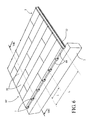
- FIG. 8 illustrates in detail the end of a beam 1 resting on a load-bearing wall 2, the interjoists 60 placed end-to-end and the distribution slabs 50 fitted side-by-side in the interjoists 60.
- the covering tabs 62 of FIGS. interjoists 60 allow to close the space between the beam 1 and the load-bearing wall 2. After assembly and assembly of intervous 60 and slabs of distribution 50, the ends of the beams 1 are sealed with respect to the supporting structure 2 by means of, for example, a reinforcement and a pouring of sealing concrete or by any other known method.
- the dry floor 10 ' is finished and is ready to receive any type of dressing according to the interior decoration.
- a thermal and / or phonic insulation in the form of, for example, a coating integrated with the distribution slabs or a sheet of material interposed between the beams. and the distribution slabs.
Landscapes
- Engineering & Computer Science (AREA)
- Architecture (AREA)
- Physics & Mathematics (AREA)
- Electromagnetism (AREA)
- Civil Engineering (AREA)
- Structural Engineering (AREA)
- Building Environments (AREA)
- Floor Finish (AREA)
Priority Applications (1)
| Application Number | Priority Date | Filing Date | Title |
|---|---|---|---|
| PL07360015T PL1847659T3 (pl) | 2006-04-10 | 2007-04-05 | Suchy stop składający się z zestawu prefabrykowanych płyt wyposażonych w rowki |
Applications Claiming Priority (1)
| Application Number | Priority Date | Filing Date | Title |
|---|---|---|---|
| FR0603135A FR2899612B1 (fr) | 2006-04-10 | 2006-04-10 | Procede de fabrication d'un plancher sec et plancher sec obtenu par ledit procede |
Publications (2)
| Publication Number | Publication Date |
|---|---|
| EP1847659A1 true EP1847659A1 (de) | 2007-10-24 |
| EP1847659B1 EP1847659B1 (de) | 2013-11-20 |
Family
ID=37513839
Family Applications (1)
| Application Number | Title | Priority Date | Filing Date |
|---|---|---|---|
| EP07360015.7A Active EP1847659B1 (de) | 2006-04-10 | 2007-04-05 | Trockenverlegter Fussboden mit Nuten versehenen vorgefertigten Bodenplatten |
Country Status (3)
| Country | Link |
|---|---|
| EP (1) | EP1847659B1 (de) |
| FR (1) | FR2899612B1 (de) |
| PL (1) | PL1847659T3 (de) |
Cited By (1)
| Publication number | Priority date | Publication date | Assignee | Title |
|---|---|---|---|---|
| ITUA20164023A1 (it) * | 2016-06-01 | 2017-12-01 | Febo S R L | Solaio con isolamento acustico e termico e resistenza al fuoco |
Citations (6)
| Publication number | Priority date | Publication date | Assignee | Title |
|---|---|---|---|---|
| US2083725A (en) * | 1932-02-26 | 1937-06-15 | United States Gypsum Co | Preformed slab building structure |
| DE911068C (de) * | 1951-12-30 | 1954-05-10 | Fritz Grebner | Aus fabrikmaessig hergestellten metallbewehrten Betontragbalken und Betonplatten erstellte, schalungsfrei verlegte Betondecke |
| EP0139798A1 (de) * | 1983-10-28 | 1985-05-08 | Trent Jetfloor Limited | Trockenverlegter Fussboden |
| FR2583805A1 (fr) * | 1985-06-21 | 1986-12-26 | Henry Cie Sa | Entrevous agence pour supporter une structure de revetement sous-jacente |
| FR2800111A1 (fr) * | 1999-10-22 | 2001-04-27 | Rector Sa | Plancher emboitable |
| US20030110727A1 (en) * | 1999-07-19 | 2003-06-19 | Gregori Karl H. W. | Decking assembly and decking kit with hold-down clip |
-
2006
- 2006-04-10 FR FR0603135A patent/FR2899612B1/fr not_active Expired - Fee Related
-
2007
- 2007-04-05 PL PL07360015T patent/PL1847659T3/pl unknown
- 2007-04-05 EP EP07360015.7A patent/EP1847659B1/de active Active
Patent Citations (6)
| Publication number | Priority date | Publication date | Assignee | Title |
|---|---|---|---|---|
| US2083725A (en) * | 1932-02-26 | 1937-06-15 | United States Gypsum Co | Preformed slab building structure |
| DE911068C (de) * | 1951-12-30 | 1954-05-10 | Fritz Grebner | Aus fabrikmaessig hergestellten metallbewehrten Betontragbalken und Betonplatten erstellte, schalungsfrei verlegte Betondecke |
| EP0139798A1 (de) * | 1983-10-28 | 1985-05-08 | Trent Jetfloor Limited | Trockenverlegter Fussboden |
| FR2583805A1 (fr) * | 1985-06-21 | 1986-12-26 | Henry Cie Sa | Entrevous agence pour supporter une structure de revetement sous-jacente |
| US20030110727A1 (en) * | 1999-07-19 | 2003-06-19 | Gregori Karl H. W. | Decking assembly and decking kit with hold-down clip |
| FR2800111A1 (fr) * | 1999-10-22 | 2001-04-27 | Rector Sa | Plancher emboitable |
Cited By (1)
| Publication number | Priority date | Publication date | Assignee | Title |
|---|---|---|---|---|
| ITUA20164023A1 (it) * | 2016-06-01 | 2017-12-01 | Febo S R L | Solaio con isolamento acustico e termico e resistenza al fuoco |
Also Published As
| Publication number | Publication date |
|---|---|
| PL1847659T3 (pl) | 2014-05-30 |
| FR2899612A1 (fr) | 2007-10-12 |
| FR2899612B1 (fr) | 2009-11-27 |
| EP1847659B1 (de) | 2013-11-20 |
Similar Documents
| Publication | Publication Date | Title |
|---|---|---|
| EP0112213B1 (de) | Aussen isolierter Betonstein und Verfahren zum Zusammenbau | |
| WO2014053905A2 (fr) | Poutrelle structuree et element modulaire de construction realise avec cette poutrelle | |
| EP2792806B1 (de) | Vorgefertigte platte mit unterbrochener wärmebrücke, ihr herstellungsverfahren und baumethode einer decke mit einer solchen platte | |
| EP1427897B1 (de) | Hochwirksamer isolierungsfüllkörper zur herstellung von decken | |
| EP1149213B1 (de) | Platte, zusammenbau solcher platten und verwendung zum aufnehmen schwerer lasten | |
| EP1847659B1 (de) | Trockenverlegter Fussboden mit Nuten versehenen vorgefertigten Bodenplatten | |
| WO2009092890A2 (fr) | Elément modulaire préfabriqué de plancher sec, procédé de fabrication d'un tel élément modulaire et plancher sec comprenant une pluralité d'éléments modulaires | |
| FR3127240A1 (fr) | Élément de plancher fini préfabriqué, procédé de fabrication d’un plancher et plancher obtenu | |
| EP3058150A2 (de) | Konstruktionsmodul auf grundlage von pappe und herstellungsverfahren dafür | |
| BE1017285A3 (fr) | Entrevous isolant pour plancher a poutrelles et plancher obtenu. | |
| EP2444567B1 (de) | Verschalungselement zum Bau eines Trägers | |
| EP2576933A2 (de) | Kartonbauelement und konstruktionsverfahren unter verwendung solcher elemente | |
| EP2789760B1 (de) | Isolationsanordnung einer decke über einem kriechraum | |
| EP2357293A1 (de) | Füllstein für Trägerdecken | |
| EP0674136B1 (de) | Wärmedämmplatte für integrierte Heizungs- und/oder Klimatisierungsanlagen und Verfahren zur Herstellung solcher Platten | |
| FR3132725A1 (fr) | Dalle de plancher à rupture de pont thermique, procédé de fabrication d’un plancher et plancher obtenu | |
| FR2962462A1 (fr) | Panneau isolant pour l'execution de parois de batiment et son procede de fabrication | |
| FR2913993A1 (fr) | Entrevous en matrice minerale, dispositif de plancher a entrevous et son procede de realisation | |
| EP2767646A1 (de) | Isolieraufbau für eine Trägerdecke über einem Kriechraum | |
| FR2790021A1 (fr) | Poutre de construction en bois comportant au moins une reservation verticale pour l'insertion d'un isolant | |
| BE1025884B1 (fr) | Procede de fabrication d'un mur interieur et mur interieur obtenu | |
| WO2007045744A1 (fr) | Coffrage isolant pour parois en beton | |
| EP2464798B1 (de) | Vorgefertigtes bauelement, zur vermeidung von wärmebrücken | |
| FR2530705A1 (fr) | Elements de construction pour la prefabrication notamment de planchers | |
| FR2691191A1 (fr) | Mur à double paroi avec correction thermique, acoustique et hygrométrique, et procédé de fabrication de ses blocs constitutifs. |
Legal Events
| Date | Code | Title | Description |
|---|---|---|---|
| PUAI | Public reference made under article 153(3) epc to a published international application that has entered the european phase |
Free format text: ORIGINAL CODE: 0009012 |
|
| AK | Designated contracting states |
Kind code of ref document: A1 Designated state(s): AT BE BG CH CY CZ DE DK EE ES FI FR GB GR HU IE IS IT LI LT LU LV MC MT NL PL PT RO SE SI SK TR |
|
| AX | Request for extension of the european patent |
Extension state: AL BA HR MK YU |
|
| 17P | Request for examination filed |
Effective date: 20080110 |
|
| AKX | Designation fees paid |
Designated state(s): AT BE BG CH CY CZ DE DK EE ES FI FR GB GR HU IE IS IT LI LT LU LV MC MT NL PL PT RO SE SI SK TR |
|
| 17Q | First examination report despatched |
Effective date: 20110225 |
|
| REG | Reference to a national code |
Ref country code: DE Ref legal event code: R079 Ref document number: 602007033865 Country of ref document: DE Free format text: PREVIOUS MAIN CLASS: E04B0005020000 Ipc: E04B0005140000 |
|
| GRAP | Despatch of communication of intention to grant a patent |
Free format text: ORIGINAL CODE: EPIDOSNIGR1 |
|
| RIC1 | Information provided on ipc code assigned before grant |
Ipc: E04B 5/14 20060101AFI20130507BHEP Ipc: E04B 5/06 20060101ALI20130507BHEP Ipc: E04B 5/04 20060101ALI20130507BHEP |
|
| INTG | Intention to grant announced |
Effective date: 20130613 |
|
| GRAS | Grant fee paid |
Free format text: ORIGINAL CODE: EPIDOSNIGR3 |
|
| GRAP | Despatch of communication of intention to grant a patent |
Free format text: ORIGINAL CODE: EPIDOSNIGR1 |
|
| GRAA | (expected) grant |
Free format text: ORIGINAL CODE: 0009210 |
|
| INTG | Intention to grant announced |
Effective date: 20130930 |
|
| AK | Designated contracting states |
Kind code of ref document: B1 Designated state(s): AT BE BG CH CY CZ DE DK EE ES FI FR GB GR HU IE IS IT LI LT LU LV MC MT NL PL PT RO SE SI SK TR |
|
| REG | Reference to a national code |
Ref country code: GB Ref legal event code: FG4D Free format text: NOT ENGLISH |
|
| REG | Reference to a national code |
Ref country code: CH Ref legal event code: EP |
|
| REG | Reference to a national code |
Ref country code: AT Ref legal event code: REF Ref document number: 641757 Country of ref document: AT Kind code of ref document: T Effective date: 20131215 |
|
| REG | Reference to a national code |
Ref country code: IE Ref legal event code: FG4D Free format text: LANGUAGE OF EP DOCUMENT: FRENCH |
|
| REG | Reference to a national code |
Ref country code: DE Ref legal event code: R096 Ref document number: 602007033865 Country of ref document: DE Effective date: 20140116 |
|
| REG | Reference to a national code |
Ref country code: NL Ref legal event code: VDEP Effective date: 20131120 |
|
| REG | Reference to a national code |
Ref country code: AT Ref legal event code: MK05 Ref document number: 641757 Country of ref document: AT Kind code of ref document: T Effective date: 20131120 |
|
| REG | Reference to a national code |
Ref country code: LT Ref legal event code: MG4D |
|
| PG25 | Lapsed in a contracting state [announced via postgrant information from national office to epo] |
Ref country code: SE Free format text: LAPSE BECAUSE OF FAILURE TO SUBMIT A TRANSLATION OF THE DESCRIPTION OR TO PAY THE FEE WITHIN THE PRESCRIBED TIME-LIMIT Effective date: 20131120 Ref country code: LT Free format text: LAPSE BECAUSE OF FAILURE TO SUBMIT A TRANSLATION OF THE DESCRIPTION OR TO PAY THE FEE WITHIN THE PRESCRIBED TIME-LIMIT Effective date: 20131120 Ref country code: FI Free format text: LAPSE BECAUSE OF FAILURE TO SUBMIT A TRANSLATION OF THE DESCRIPTION OR TO PAY THE FEE WITHIN THE PRESCRIBED TIME-LIMIT Effective date: 20131120 Ref country code: IS Free format text: LAPSE BECAUSE OF FAILURE TO SUBMIT A TRANSLATION OF THE DESCRIPTION OR TO PAY THE FEE WITHIN THE PRESCRIBED TIME-LIMIT Effective date: 20140320 Ref country code: NL Free format text: LAPSE BECAUSE OF FAILURE TO SUBMIT A TRANSLATION OF THE DESCRIPTION OR TO PAY THE FEE WITHIN THE PRESCRIBED TIME-LIMIT Effective date: 20131120 |
|
| PG25 | Lapsed in a contracting state [announced via postgrant information from national office to epo] |
Ref country code: ES Free format text: LAPSE BECAUSE OF FAILURE TO SUBMIT A TRANSLATION OF THE DESCRIPTION OR TO PAY THE FEE WITHIN THE PRESCRIBED TIME-LIMIT Effective date: 20131120 Ref country code: AT Free format text: LAPSE BECAUSE OF FAILURE TO SUBMIT A TRANSLATION OF THE DESCRIPTION OR TO PAY THE FEE WITHIN THE PRESCRIBED TIME-LIMIT Effective date: 20131120 Ref country code: LV Free format text: LAPSE BECAUSE OF FAILURE TO SUBMIT A TRANSLATION OF THE DESCRIPTION OR TO PAY THE FEE WITHIN THE PRESCRIBED TIME-LIMIT Effective date: 20131120 |
|
| REG | Reference to a national code |
Ref country code: PL Ref legal event code: T3 |
|
| REG | Reference to a national code |
Ref country code: SK Ref legal event code: T3 Ref document number: E 15949 Country of ref document: SK |
|
| PG25 | Lapsed in a contracting state [announced via postgrant information from national office to epo] |
Ref country code: PT Free format text: LAPSE BECAUSE OF FAILURE TO SUBMIT A TRANSLATION OF THE DESCRIPTION OR TO PAY THE FEE WITHIN THE PRESCRIBED TIME-LIMIT Effective date: 20140320 |
|
| PG25 | Lapsed in a contracting state [announced via postgrant information from national office to epo] |
Ref country code: EE Free format text: LAPSE BECAUSE OF FAILURE TO SUBMIT A TRANSLATION OF THE DESCRIPTION OR TO PAY THE FEE WITHIN THE PRESCRIBED TIME-LIMIT Effective date: 20131120 |
|
| REG | Reference to a national code |
Ref country code: DE Ref legal event code: R097 Ref document number: 602007033865 Country of ref document: DE |
|
| PG25 | Lapsed in a contracting state [announced via postgrant information from national office to epo] |
Ref country code: RO Free format text: LAPSE BECAUSE OF FAILURE TO SUBMIT A TRANSLATION OF THE DESCRIPTION OR TO PAY THE FEE WITHIN THE PRESCRIBED TIME-LIMIT Effective date: 20131120 |
|
| PLBE | No opposition filed within time limit |
Free format text: ORIGINAL CODE: 0009261 |
|
| STAA | Information on the status of an ep patent application or granted ep patent |
Free format text: STATUS: NO OPPOSITION FILED WITHIN TIME LIMIT |
|
| PG25 | Lapsed in a contracting state [announced via postgrant information from national office to epo] |
Ref country code: DK Free format text: LAPSE BECAUSE OF FAILURE TO SUBMIT A TRANSLATION OF THE DESCRIPTION OR TO PAY THE FEE WITHIN THE PRESCRIBED TIME-LIMIT Effective date: 20131120 |
|
| 26N | No opposition filed |
Effective date: 20140821 |
|
| REG | Reference to a national code |
Ref country code: DE Ref legal event code: R119 Ref document number: 602007033865 Country of ref document: DE |
|
| PG25 | Lapsed in a contracting state [announced via postgrant information from national office to epo] |
Ref country code: LU Free format text: LAPSE BECAUSE OF FAILURE TO SUBMIT A TRANSLATION OF THE DESCRIPTION OR TO PAY THE FEE WITHIN THE PRESCRIBED TIME-LIMIT Effective date: 20140405 Ref country code: MC Free format text: LAPSE BECAUSE OF FAILURE TO SUBMIT A TRANSLATION OF THE DESCRIPTION OR TO PAY THE FEE WITHIN THE PRESCRIBED TIME-LIMIT Effective date: 20131120 |
|
| REG | Reference to a national code |
Ref country code: CH Ref legal event code: PL |
|
| REG | Reference to a national code |
Ref country code: DE Ref legal event code: R097 Ref document number: 602007033865 Country of ref document: DE Effective date: 20140821 |
|
| GBPC | Gb: european patent ceased through non-payment of renewal fee |
Effective date: 20140405 |
|
| REG | Reference to a national code |
Ref country code: DE Ref legal event code: R119 Ref document number: 602007033865 Country of ref document: DE Effective date: 20141101 |
|
| REG | Reference to a national code |
Ref country code: IE Ref legal event code: MM4A |
|
| PG25 | Lapsed in a contracting state [announced via postgrant information from national office to epo] |
Ref country code: LI Free format text: LAPSE BECAUSE OF NON-PAYMENT OF DUE FEES Effective date: 20140430 Ref country code: DE Free format text: LAPSE BECAUSE OF NON-PAYMENT OF DUE FEES Effective date: 20141101 Ref country code: GB Free format text: LAPSE BECAUSE OF NON-PAYMENT OF DUE FEES Effective date: 20140405 Ref country code: CH Free format text: LAPSE BECAUSE OF NON-PAYMENT OF DUE FEES Effective date: 20140430 |
|
| PG25 | Lapsed in a contracting state [announced via postgrant information from national office to epo] |
Ref country code: SI Free format text: LAPSE BECAUSE OF FAILURE TO SUBMIT A TRANSLATION OF THE DESCRIPTION OR TO PAY THE FEE WITHIN THE PRESCRIBED TIME-LIMIT Effective date: 20131120 |
|
| PG25 | Lapsed in a contracting state [announced via postgrant information from national office to epo] |
Ref country code: IT Free format text: LAPSE BECAUSE OF FAILURE TO SUBMIT A TRANSLATION OF THE DESCRIPTION OR TO PAY THE FEE WITHIN THE PRESCRIBED TIME-LIMIT Effective date: 20131120 |
|
| PG25 | Lapsed in a contracting state [announced via postgrant information from national office to epo] |
Ref country code: IE Free format text: LAPSE BECAUSE OF NON-PAYMENT OF DUE FEES Effective date: 20140405 |
|
| REG | Reference to a national code |
Ref country code: FR Ref legal event code: PLFP Year of fee payment: 9 |
|
| REG | Reference to a national code |
Ref country code: FR Ref legal event code: CJ Effective date: 20150722 |
|
| REG | Reference to a national code |
Ref country code: FR Ref legal event code: TP Owner name: LESAGE DEVELOPPEMENT S.A.S., FR Effective date: 20160204 |
|
| PG25 | Lapsed in a contracting state [announced via postgrant information from national office to epo] |
Ref country code: MT Free format text: LAPSE BECAUSE OF FAILURE TO SUBMIT A TRANSLATION OF THE DESCRIPTION OR TO PAY THE FEE WITHIN THE PRESCRIBED TIME-LIMIT Effective date: 20131120 |
|
| REG | Reference to a national code |
Ref country code: FR Ref legal event code: PLFP Year of fee payment: 10 |
|
| PG25 | Lapsed in a contracting state [announced via postgrant information from national office to epo] |
Ref country code: BG Free format text: LAPSE BECAUSE OF FAILURE TO SUBMIT A TRANSLATION OF THE DESCRIPTION OR TO PAY THE FEE WITHIN THE PRESCRIBED TIME-LIMIT Effective date: 20131120 |
|
| PG25 | Lapsed in a contracting state [announced via postgrant information from national office to epo] |
Ref country code: GR Free format text: LAPSE BECAUSE OF FAILURE TO SUBMIT A TRANSLATION OF THE DESCRIPTION OR TO PAY THE FEE WITHIN THE PRESCRIBED TIME-LIMIT Effective date: 20140221 Ref country code: CY Free format text: LAPSE BECAUSE OF FAILURE TO SUBMIT A TRANSLATION OF THE DESCRIPTION OR TO PAY THE FEE WITHIN THE PRESCRIBED TIME-LIMIT Effective date: 20131120 |
|
| PG25 | Lapsed in a contracting state [announced via postgrant information from national office to epo] |
Ref country code: HU Free format text: LAPSE BECAUSE OF FAILURE TO SUBMIT A TRANSLATION OF THE DESCRIPTION OR TO PAY THE FEE WITHIN THE PRESCRIBED TIME-LIMIT; INVALID AB INITIO Effective date: 20070405 Ref country code: TR Free format text: LAPSE BECAUSE OF FAILURE TO SUBMIT A TRANSLATION OF THE DESCRIPTION OR TO PAY THE FEE WITHIN THE PRESCRIBED TIME-LIMIT Effective date: 20131120 Ref country code: BE Free format text: LAPSE BECAUSE OF FAILURE TO SUBMIT A TRANSLATION OF THE DESCRIPTION OR TO PAY THE FEE WITHIN THE PRESCRIBED TIME-LIMIT Effective date: 20140430 |
|
| REG | Reference to a national code |
Ref country code: FR Ref legal event code: PLFP Year of fee payment: 11 |
|
| REG | Reference to a national code |
Ref country code: FR Ref legal event code: PLFP Year of fee payment: 12 |
|
| REG | Reference to a national code |
Ref country code: SK Ref legal event code: PC4A Ref document number: E 15949 Country of ref document: SK Owner name: LESAGE DEVELOPMENT, MULHOUSE, FR Free format text: FORMER OWNER: RECTOR LESAGE S.A., MULHOUSE, FR Effective date: 20180913 |
|
| PGFP | Annual fee paid to national office [announced via postgrant information from national office to epo] |
Ref country code: PL Payment date: 20200326 Year of fee payment: 14 |
|
| PGFP | Annual fee paid to national office [announced via postgrant information from national office to epo] |
Ref country code: SK Payment date: 20200313 Year of fee payment: 14 Ref country code: CZ Payment date: 20200316 Year of fee payment: 14 |
|
| PG25 | Lapsed in a contracting state [announced via postgrant information from national office to epo] |
Ref country code: CZ Free format text: LAPSE BECAUSE OF NON-PAYMENT OF DUE FEES Effective date: 20210405 |
|
| REG | Reference to a national code |
Ref country code: SK Ref legal event code: MM4A Ref document number: E 15949 Country of ref document: SK Effective date: 20210405 |
|
| PG25 | Lapsed in a contracting state [announced via postgrant information from national office to epo] |
Ref country code: SK Free format text: LAPSE BECAUSE OF NON-PAYMENT OF DUE FEES Effective date: 20210405 |
|
| PG25 | Lapsed in a contracting state [announced via postgrant information from national office to epo] |
Ref country code: PL Free format text: LAPSE BECAUSE OF NON-PAYMENT OF DUE FEES Effective date: 20210405 |
|
| PGFP | Annual fee paid to national office [announced via postgrant information from national office to epo] |
Ref country code: FR Payment date: 20250423 Year of fee payment: 19 |