EP1847682A1 - Méthode d'alimentation d'un fluide dans le flux principal de gaz d'une turbine et aube de turbine associée. - Google Patents
Méthode d'alimentation d'un fluide dans le flux principal de gaz d'une turbine et aube de turbine associée. Download PDFInfo
- Publication number
- EP1847682A1 EP1847682A1 EP06008320A EP06008320A EP1847682A1 EP 1847682 A1 EP1847682 A1 EP 1847682A1 EP 06008320 A EP06008320 A EP 06008320A EP 06008320 A EP06008320 A EP 06008320A EP 1847682 A1 EP1847682 A1 EP 1847682A1
- Authority
- EP
- European Patent Office
- Prior art keywords
- gas
- turbine
- medium
- turbine blade
- blade
- Prior art date
- Legal status (The legal status is an assumption and is not a legal conclusion. Google has not performed a legal analysis and makes no representation as to the accuracy of the status listed.)
- Withdrawn
Links
- 238000000034 method Methods 0.000 title claims abstract description 21
- 239000012530 fluid Substances 0.000 title description 7
- 238000001816 cooling Methods 0.000 claims abstract description 26
- 239000000446 fuel Substances 0.000 claims description 24
- 239000000203 mixture Substances 0.000 claims description 15
- 238000003303 reheating Methods 0.000 claims description 8
- 238000011144 upstream manufacturing Methods 0.000 claims description 3
- 230000007704 transition Effects 0.000 claims description 2
- 239000007789 gas Substances 0.000 description 84
- 238000002485 combustion reaction Methods 0.000 description 12
- 210000003734 kidney Anatomy 0.000 description 6
- 239000011797 cavity material Substances 0.000 description 4
- 239000002826 coolant Substances 0.000 description 4
- 206010016754 Flashback Diseases 0.000 description 3
- 238000011065 in-situ storage Methods 0.000 description 3
- 239000000654 additive Substances 0.000 description 2
- 230000015572 biosynthetic process Effects 0.000 description 2
- 238000006243 chemical reaction Methods 0.000 description 2
- 230000000694 effects Effects 0.000 description 2
- 239000008240 homogeneous mixture Substances 0.000 description 2
- 238000002347 injection Methods 0.000 description 2
- 239000007924 injection Substances 0.000 description 2
- 239000000463 material Substances 0.000 description 2
- 239000002245 particle Substances 0.000 description 2
- 239000000243 solution Substances 0.000 description 2
- 230000004323 axial length Effects 0.000 description 1
- 230000000903 blocking effect Effects 0.000 description 1
- 238000007664 blowing Methods 0.000 description 1
- 230000008859 change Effects 0.000 description 1
- 230000000739 chaotic effect Effects 0.000 description 1
- 230000007423 decrease Effects 0.000 description 1
- 230000018109 developmental process Effects 0.000 description 1
- 239000003344 environmental pollutant Substances 0.000 description 1
- 239000002737 fuel gas Substances 0.000 description 1
- 238000010438 heat treatment Methods 0.000 description 1
- 210000000003 hoof Anatomy 0.000 description 1
- 238000009434 installation Methods 0.000 description 1
- 239000007788 liquid Substances 0.000 description 1
- 238000004519 manufacturing process Methods 0.000 description 1
- 230000002093 peripheral effect Effects 0.000 description 1
- 231100000719 pollutant Toxicity 0.000 description 1
- 238000012805 post-processing Methods 0.000 description 1
- 230000008569 process Effects 0.000 description 1
- 230000035484 reaction time Effects 0.000 description 1
- 239000011369 resultant mixture Substances 0.000 description 1
- 230000003319 supportive effect Effects 0.000 description 1
Images


Classifications
-
- F—MECHANICAL ENGINEERING; LIGHTING; HEATING; WEAPONS; BLASTING
- F02—COMBUSTION ENGINES; HOT-GAS OR COMBUSTION-PRODUCT ENGINE PLANTS
- F02K—JET-PROPULSION PLANTS
- F02K3/00—Plants including a gas turbine driving a compressor or a ducted fan
- F02K3/08—Plants including a gas turbine driving a compressor or a ducted fan with supplementary heating of the working fluid; Control thereof
-
- F—MECHANICAL ENGINEERING; LIGHTING; HEATING; WEAPONS; BLASTING
- F01—MACHINES OR ENGINES IN GENERAL; ENGINE PLANTS IN GENERAL; STEAM ENGINES
- F01D—NON-POSITIVE DISPLACEMENT MACHINES OR ENGINES, e.g. STEAM TURBINES
- F01D5/00—Blades; Blade-carrying members; Heating, heat-insulating, cooling or antivibration means on the blades or the members
- F01D5/12—Blades
- F01D5/14—Form or construction
- F01D5/141—Shape, i.e. outer, aerodynamic form
- F01D5/145—Means for influencing boundary layers or secondary circulations
-
- F—MECHANICAL ENGINEERING; LIGHTING; HEATING; WEAPONS; BLASTING
- F05—INDEXING SCHEMES RELATING TO ENGINES OR PUMPS IN VARIOUS SUBCLASSES OF CLASSES F01-F04
- F05D—INDEXING SCHEME FOR ASPECTS RELATING TO NON-POSITIVE-DISPLACEMENT MACHINES OR ENGINES, GAS-TURBINES OR JET-PROPULSION PLANTS
- F05D2270/00—Control
- F05D2270/01—Purpose of the control system
- F05D2270/17—Purpose of the control system to control boundary layer
Definitions
- the invention relates to a method for feeding a medium into a gas flowing through a turbine and a turbine blade with a platform, on which a transversely extending, can be flowed around by a gas turbine blade and in the at least one opening for mixing a medium into the gas is provided.
- Such a method and a suitable for carrying out the method turbine blade is for example from the WO 2005/3517 A1 known.
- the blade walls forming the airfoil surround a cavity provided for guiding cooling air.
- further channels for guiding a second medium, namely fuel, are provided in the blade wall of the turbine blade.
- both the gas flowing through the turbine and the cooling air flowing out of the turbine blade can be reheated by burning the mixture, which is generally carried out to increase the efficiency of the gas turbine, to reduce pollutant emissions and to improve the efficiency of the gas turbine and a form of carnotization is known.
- a combustion chamber with a plurality of porous heat shield elements known by a combustible mixture subsequently, ie outside of burners of the gas turbine, can be introduced into the combustion chamber of a gas turbine.
- the reheating of the gas in the turbine by at this point subsequently i. outside the burner of the gas turbine, introduced fuel to unintentionally high emissions.
- the high emissions are due to insufficient mixing of fuel and air, as they are only supplied to a mixing chamber. Other measures that promote further mixing are not provided.
- the combustion may also take place only partially so that fuel flows out of the turbine unburnt and unused.
- the object of the invention is therefore to provide a method for supplying a medium into a gas flowing through a turbine, in which the components of the medium are mixed particularly efficiently.
- a further object of the invention is to provide a generic turbine blade with which a medium which can be flowed out of it can be mixed particularly efficiently with the medium flowing around the turbine blade.
- the medium at a those points are supplied to the gas, at which a vortex of a flow occurs and / or at which the vortex flows along.
- the solution of the task directed to the turbine blade provides that the generic turbine blade has the opening at a location in the surface of the airfoil or in the surface of the platform at which a flow medium flows in a vortex-like manner.
- the invention is based on the recognition that the vortex systems naturally occurring in the flow can be used to subdue the medium of the flow, since the best possible mixing is desired.
- the improved mixing is thus achieved without significant structural change of the gas space or the turbine blade.
- the vortex energy already present in the vortex systems of the flow can be used efficiently for the mixing of the media.
- the gas flowing through the gas space can have the turbulent flow in which the vortices form due to the geometry of the gas space. It is also possible to dispense with any necessary flow installations and to maintain the aerodynamic capability of the component.
- Vortexes are circular flows of a fluid, in which the respective fluid particles move in concentric circular paths.
- the vertebrae may be formed, for example, as Karman vortex streets, as corner vertebrae, canal vertebrae or as hoof vertebrae.
- the vortices differ substantially from the turbulence, which is spatially and temporally disordered, i. chaotic flow of a gas or a liquid.
- Turbulent flows in contrast to laminar flows, contain such numerous turbulences with a wide range of length and time scales that they are unpredictable due to the random nature of the flow condition and velocities.
- the medium when the medium is to be mixed as a fuel mixture or fuel for reheating the gas flowing through the turbine, what is known as "in-situ blade reheat" is, it proves to be particularly advantageous if this medium is injected into a horseshoe vortex or Kärmän vortex.
- the particularly efficient mixing leads to particularly short burnout times, whereby a low-emission combustion of the fuel or fuel mixture is achieved by auto-ignition in the gas. Consequently, the proposed solution allows the rapid mixing of fuel or other fluids with the gas of the turbine, without the risk of flashbacks or autoignition of a possibly reactive mixture, since the vortices are backflow-free. It can be minimized by the utilization of vortex systems already present in the flow field of the gas, the design effort and the aerodynamic losses in the working fluid.
- the fast burnout time achieved with the invention enables comparatively short turbine lengths, i.
- the axial length can be shortened or not extended for the use of the method. This saves material and manufacturing costs.
- the first medium is blown into a cooling flow emerging from a film cooling opening.
- the turbulent flow can thus also comprise a cooling air flow, which flows out of the film cooling opening as a kidney vortex.
- film cooling holes are designed as so-called “fan-shaped holes", which do not have a circular or, due to their inclination to the surface, oval opening, but due to post-processing a diverging diffuser region, so that the coolant flowing from the diffuser opening generates a backflow-free kidney vertebra , This kidney vortex can be used for mixing a fuel with the cooling flow, which is preferably cooling air.
- a horseshoe vortex of the gas is caused by an airfoil of the turbine or by a turbulizer. Due to the impact of the gas on the leading edge of the blade in the region of the platform, horseshoe vortices arise in this area, which propagate along the blade. The medium can be injected into these vortices for particularly efficient mixing.
- the opening from which the first medium is blown into the gas space is provided in a transition region arranged between the platform and the blade, since the impact of the gas flow causes horseshoe vortices in the gas, especially in this area.
- the opening in the platform downstream of a trailing edge of the airfoil or is arranged laterally of the airfoil. It is also possible to arrange the opening in the platform in front of a leading edge of the airfoil, with respect to the direction of flow of the gas.
- the platform and / or on the blade may be necessary to provide means for generating vortices on the platform and / or on the blade, from which the first fluid that can be supplied to the vertebrae can be flowed out.
- these means may be some cylinder-like projections or ribs, which are arranged on the platform or the blade and from which the first medium can be flowed out.
- a gas turbine equipped with such a turbine blade or a gas turbine, in which the method according to the invention runs, is particularly suitable for manipulating the working medium or gas flowing through it by supplying media or additives.
- the energy content of the gas can be increased by "in-situ blade reheat" or the emission load of the working medium can be lowered by the addition of additives.
- FIG. 1 shows a gas turbine 1 in a longitudinal partial section. It has inside a rotatably mounted about a rotation axis 2 rotor 3, which is also referred to as a turbine runner. Along the rotor 3 successive an intake 4, a compressor 5, a toroidal annular combustion chamber 6 with a plurality of rotationally symmetrical to each other arranged burners 7, a turbine unit 8 and an exhaust housing 9.
- the annular combustion chamber 6 forms a combustion chamber 17, which communicates with a ring-channel gas space 18.
- There four successive turbine stages 10 form the turbine unit 8. Each turbine stage 10 is formed of two blade rings.
- one row of guide vanes 13 follows one of the rotor blades 15 formed row 14.
- the vanes 12 are attached to the stator, whereas the blades 15 of a row 14 are each mounted by means of a turbine disk on the rotor 3.
- a generator or a working machine (not shown) is coupled.
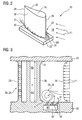
- the generally cast turbine blade 20 may be formed both as a guide blade 12 or as a rotor blade 15, the platform 22 the arranged in the turbine unit 8 gas space 18 radially outside and / or radially inwardly partially limited.
- the airfoil 24 extends from a leading edge 26 to a trailing edge 28, with a suction side sidewall 30 and a pressure side sidewall 32 forming the airfoil 24.
- the turbine blade 20 is partially hollow for guiding a first medium and suitable in the manner described below for supplying a first medium M1 flowing through the cavities to the gas 11 flowing around the blade 24.
- openings 31 are provided in the surface of the platform 22 exposed to the gas 11 upstream of the front edge 26, through which openings the first medium M1, preferably fuel, can be blown out.
- the hot gas 11 flowing along the gas space 18 is divided by each of the blades 24 arranged therein into two partial streams which flow along each blade 24 on both sides. Due to the radially outer boundary of the gas space 18 and due to the radially inner boundary of the gas space 18 through the platforms 22 of the turbine blade 20 arise on the platform side at the leading edges 26 of the blades 24 so-called secondary flows as part of the hot gas 11, for example, as horseshoe vortices 33, 34th each flow along the side walls 30, 32 of the airfoil 24 in concentric circular paths.
- the vortices 33, 34 are formed as circular or spiral flows, where all fluid particles move on concentric circular paths. All successive centers of the advancing circular or spiral paths describe a vortex axis, which is denoted by 51.
- FIG. 3 partly shows the turbine blade 20 shown in FIG. 2 in longitudinal section.
- the leading edge 26 of the airfoil 24 passes over a radius R in the platform 22, in which a plurality of mutually parallel, obliquely to the surface of the platform 22 arranged holes 50 are provided, which open into a lying inside the platform 22 supply channel 52.
- the supply channel 52, the first medium M1 from outside the turbine blade 20 can be fed.
- the gas 11 flowing toward the front edge 26 of the turbine blade 20 and its velocity profile 35 along the radial direction of the gas space 18 are shown.
- the gas 11 flowing past the inner platform 22 flows due to the friction with the surface of the platform 22 at a comparatively low speed (shorter arrow lengths).
- the local flow velocity within a short distance is greater (longer arrow lengths) until it has reached a maximum value.
- the flow rate remains constant at the maximum value until it decreases in the region of the outer platform 22 of the turbine blade 20 in the same manner as on the inner platform 22.
- the backflow vortex 33, 34 Due to the slowed down at the outer and inner regions velocity profile of the gas 11 and due to the blocking of the gas space 18 by the blades 24 of the arranged in the annular channel gas chamber 18 turbine blades 20 are the impact of the gas 11 at the leading edges 26 in the area of the platforms 22, the backflow vortex 33, 34 generates, whose Vortex energy is used to mix the effluent from the bores 50 first medium M1 with the gas 11. The emerging from the holes 50 first medium M1 is thereby injected almost perpendicular to the vortex axis 51 in the vortex. After the formation of the vortices 33, 34, this part of the gas 11 flows along the airfoil until, after a certain swirling length, it collapses. This process can be used to stabilize the existing flame for combustion of the mixture.
- the ejection of the fuel flowing through the bores 50 proceeds in a supportive manner from the vortices 33, 34, since a vacuum is created locally on the platform surface due to the vortices 33, 34, which sucks the fuel out of the bores 50. A flashback is so safely avoided.
- the first medium M1 is supplied at those locations of the turbine blade 20 to the gas 11, at which the vortex 33, 34 is generated.
- This method can be used, in particular, for reheating the gas 11 flowing through the turbine 8, in which a fuel or a fuel mixture is admixed as best as possible with the gas 11 as the first medium M1.
- swirling elements 64 shown in an exemplary and disproportionately large manner in FIG. 4 are provided both on the suction-side blade wall 30 and on the surface of the platform 22 exposed to the gas 11 in the form of protruding cylindrical pins 36.
- the molded on the turbine blade 20 pins 36 are as shown in FIG 6, as well as the turbine blade 20 partially hollow and have inside extending channels 40, through which the first medium M1 is flown to then through the openings 42 in the gas flowing around the blade 24 24 to be injected with appropriate pressure.
- the first medium M1 is preferably fuel.
- the gas 11 impinging thereon is divided into two mutually influencing Karman vortices 33, 34, which continue along the main flow direction of the gas 11.
- the meanwhile flowing out of the pin 36 on the peripheral surface medium M1 is entrained at this point by the vortices and thereby particularly efficiently mixed with the gas 11, so that an extremely homogeneous mixture is formed which ignites for reheating the gas 11 automatically.
- a backflow of the combustible mixture is prevented in the turbine blade 20 by the caused by the vertebrae 33, 34 removal; the combustible mixture is moved away from the opening 42.
- the medium M1 can be injected perpendicularly into the gas 11 flowing around the airfoil 24, the same effect being produced by the almost vertical injection of the medium M1.
- horseshoe vortices in the gas 11 can also be caused thereby.
- a bore is conceivable, from which the medium can be blown into the gas almost vertically at high flow velocity.
- the mixing energy is obtained from the gas 11.
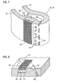
- FIG. 7 is a sectioned partial perspective view of the airfoil 24 of the turbine blade 20 shown in FIG.
- the airfoil 24 is hollow in the interior with a cavity 60 which is suitable as a second medium to guide a coolant M2, which can flow through laser drilled and subsequently produced by EDM, referred to as "fan-shapes holes" openings 62 and a generated on the surface of the airfoil 24 flowing cooling air film.
- a porous insert 66 is provided downstream of the film cooling openings 62, which delimits a fuel channel 68 lying in the blade wall 30 and through which the first medium M1 fed to the fuel channel 68 can exit.
- the coolant emerging from the film cooling openings 62 flows in a kidney-like manner over the porous insert 66 and in the meantime mixes with the fuel blown out there.
- swirling elements 64 such as turbulators or pins, may be provided between the film cooling port 62 and the porous insert 66 to effect further swirling of the cooling air exiting the film cooling port 62 and thus improved mixing and less-emissions combustion.
- the first medium M1 preferably fuel
- the first medium M1 introduced into the flow can be mixed in particularly efficiently, since the energy contained in the vortices is used to produce a homogeneous mixture.
- the gas 11 Due to the homogeneous mixing, the gas 11 is enriched evenly with fuel, which ignites automatically due to the temperatures occurring in the gas 11 and can be used due to the thereby adjusting short Ausbranddauer and reaction path for low-emission reheating of the turbine 8.
- FIG. 8 furthermore shows in detail a diverging film cooling opening 62 in the manner of a "fan-shaped hole” with a kidney vortex 70 which adjusts itself due to the circumferential contour of the opening 62, in which the fuel gas flowing out of the porous insert 66 is mixed in efficiently.
Landscapes
- Engineering & Computer Science (AREA)
- Mechanical Engineering (AREA)
- General Engineering & Computer Science (AREA)
- Chemical & Material Sciences (AREA)
- Combustion & Propulsion (AREA)
- Physics & Mathematics (AREA)
- Fluid Mechanics (AREA)
- Turbine Rotor Nozzle Sealing (AREA)
Priority Applications (1)
| Application Number | Priority Date | Filing Date | Title |
|---|---|---|---|
| EP06008320A EP1847682A1 (fr) | 2006-04-21 | 2006-04-21 | Méthode d'alimentation d'un fluide dans le flux principal de gaz d'une turbine et aube de turbine associée. |
Applications Claiming Priority (1)
| Application Number | Priority Date | Filing Date | Title |
|---|---|---|---|
| EP06008320A EP1847682A1 (fr) | 2006-04-21 | 2006-04-21 | Méthode d'alimentation d'un fluide dans le flux principal de gaz d'une turbine et aube de turbine associée. |
Publications (1)
| Publication Number | Publication Date |
|---|---|
| EP1847682A1 true EP1847682A1 (fr) | 2007-10-24 |
Family
ID=37411855
Family Applications (1)
| Application Number | Title | Priority Date | Filing Date |
|---|---|---|---|
| EP06008320A Withdrawn EP1847682A1 (fr) | 2006-04-21 | 2006-04-21 | Méthode d'alimentation d'un fluide dans le flux principal de gaz d'une turbine et aube de turbine associée. |
Country Status (1)
| Country | Link |
|---|---|
| EP (1) | EP1847682A1 (fr) |
Cited By (9)
| Publication number | Priority date | Publication date | Assignee | Title |
|---|---|---|---|---|
| JP2007321766A (ja) * | 2006-06-05 | 2007-12-13 | General Electric Co <Ge> | 第1段ノズルからの二次燃料噴射にかかるシステム及び方法 |
| EP2065563A3 (fr) * | 2007-11-29 | 2012-05-09 | United Technologies Corporation | Systèmes de moteurs à turbine à gaz impliquant des zones de gorge d'aube mécaniquement modifiables |
| DE102013224050B3 (de) * | 2013-08-23 | 2014-11-27 | Deutsches Zentrum für Luft- und Raumfahrt e.V. | Axialverdichter |
| US20230036499A1 (en) * | 2021-07-30 | 2023-02-02 | Honeywell International Inc. | System and method for turbomachine with local vortex generator array |
| US11971170B1 (en) * | 2022-12-30 | 2024-04-30 | Ge Infrastructure Technology Llc | System and method having flame stabilizers for isothermal expansion in turbine stage of gas turbine engine |
| US12037951B1 (en) * | 2022-12-30 | 2024-07-16 | Ge Infrastructure Technology Llc | System and method having load control for isothermal expansion in turbine stage of gas turbine engine |
| FR3151232A1 (fr) * | 2023-07-21 | 2025-01-24 | Safran Aircraft Engines | Procede de fabrication d’une aube de turbine de turbomachine |
| US12228072B2 (en) | 2022-12-30 | 2025-02-18 | Ge Infrastructure Technology Llc | System and method having multi-fluid injectors for isothermal expansion in turbine stage of gas turbine engine |
| US12540581B2 (en) | 2022-12-30 | 2026-02-03 | Ge Vernova Infrastructure Technology Llc | System and method having fluid injectors for isothermal expansion in turbine stage of gas turbine engine |
Citations (4)
| Publication number | Priority date | Publication date | Assignee | Title |
|---|---|---|---|---|
| JPS60219401A (ja) * | 1984-04-17 | 1985-11-02 | Unyusho Senpaku Gijutsu Kenkyusho | ガスタ−ビンの再熱用燃料吹出し翼 |
| WO2004029415A1 (fr) * | 2002-09-26 | 2004-04-08 | Siemens Westinghouse Power Corporation | Dispositif de guidage de fluide de perturbation de vortex thermotolerant |
| EP1431543A2 (fr) * | 2002-12-20 | 2004-06-23 | General Electric Company | Système à turbine et injecteur de combustible associé |
| EP1491722A2 (fr) * | 2003-06-24 | 2004-12-29 | Siemens Westinghouse Power Corporation | Refroidissement du conge de raccordement d'aubes de turbine a combustion |
-
2006
- 2006-04-21 EP EP06008320A patent/EP1847682A1/fr not_active Withdrawn
Patent Citations (4)
| Publication number | Priority date | Publication date | Assignee | Title |
|---|---|---|---|---|
| JPS60219401A (ja) * | 1984-04-17 | 1985-11-02 | Unyusho Senpaku Gijutsu Kenkyusho | ガスタ−ビンの再熱用燃料吹出し翼 |
| WO2004029415A1 (fr) * | 2002-09-26 | 2004-04-08 | Siemens Westinghouse Power Corporation | Dispositif de guidage de fluide de perturbation de vortex thermotolerant |
| EP1431543A2 (fr) * | 2002-12-20 | 2004-06-23 | General Electric Company | Système à turbine et injecteur de combustible associé |
| EP1491722A2 (fr) * | 2003-06-24 | 2004-12-29 | Siemens Westinghouse Power Corporation | Refroidissement du conge de raccordement d'aubes de turbine a combustion |
Cited By (14)
| Publication number | Priority date | Publication date | Assignee | Title |
|---|---|---|---|---|
| JP2007321766A (ja) * | 2006-06-05 | 2007-12-13 | General Electric Co <Ge> | 第1段ノズルからの二次燃料噴射にかかるシステム及び方法 |
| EP2065563A3 (fr) * | 2007-11-29 | 2012-05-09 | United Technologies Corporation | Systèmes de moteurs à turbine à gaz impliquant des zones de gorge d'aube mécaniquement modifiables |
| DE102013224050B3 (de) * | 2013-08-23 | 2014-11-27 | Deutsches Zentrum für Luft- und Raumfahrt e.V. | Axialverdichter |
| US20230036499A1 (en) * | 2021-07-30 | 2023-02-02 | Honeywell International Inc. | System and method for turbomachine with local vortex generator array |
| US11885234B2 (en) * | 2021-07-30 | 2024-01-30 | Honeywell International Inc. | System and method for turbomachine with local vortex generator array |
| US12286896B2 (en) | 2021-07-30 | 2025-04-29 | Honeywell International Inc. | System and method for turbomachine with local vortex generator array |
| US12037951B1 (en) * | 2022-12-30 | 2024-07-16 | Ge Infrastructure Technology Llc | System and method having load control for isothermal expansion in turbine stage of gas turbine engine |
| US12228072B2 (en) | 2022-12-30 | 2025-02-18 | Ge Infrastructure Technology Llc | System and method having multi-fluid injectors for isothermal expansion in turbine stage of gas turbine engine |
| US12247739B2 (en) | 2022-12-30 | 2025-03-11 | Ge Infrastructure Technology Llc | System and method having flame stabilizers for isothermal expansion in turbine stage of gas turbine engine |
| US11971170B1 (en) * | 2022-12-30 | 2024-04-30 | Ge Infrastructure Technology Llc | System and method having flame stabilizers for isothermal expansion in turbine stage of gas turbine engine |
| US12339001B2 (en) | 2022-12-30 | 2025-06-24 | Ge Infrastructure Technology Llc | System and method having flame stabilizers for isothermal expansion in turbine stage of gas turbine engine |
| US12540581B2 (en) | 2022-12-30 | 2026-02-03 | Ge Vernova Infrastructure Technology Llc | System and method having fluid injectors for isothermal expansion in turbine stage of gas turbine engine |
| FR3151232A1 (fr) * | 2023-07-21 | 2025-01-24 | Safran Aircraft Engines | Procede de fabrication d’une aube de turbine de turbomachine |
| WO2025022059A1 (fr) * | 2023-07-21 | 2025-01-30 | Safran Aircraft Engines | Procede de fabrication d'une aube de turbine de turbomachine |
Similar Documents
| Publication | Publication Date | Title |
|---|---|---|
| EP2010757B1 (fr) | Aube de turbine | |
| DE102007004864C5 (de) | Brennkammer einer Gasturbine und Verbrennungssteuerverfahren für eine Gasturbine | |
| DE102007004394B4 (de) | Brenner zum Verbrennen eines Vorgemischs für eine Gasturbine | |
| DE102011000198B4 (de) | System zur Kühlung von Turbinenschaufeln | |
| DE60310170T2 (de) | Brennstoffinjektionsvorrichtung | |
| EP2010773B1 (fr) | Aube de turbine | |
| DE102005024062B4 (de) | Brennerrohr und Verfahren zum Mischen von Luft und Gas in einem Gasturbinentriebwerk | |
| EP0781967B1 (fr) | Chambre de combustion annulaire pour turbine à gaz | |
| DE112004002704B4 (de) | Verbrennungsanlage | |
| DE102010036488B4 (de) | Gasturbinenbrenner | |
| EP3134677B1 (fr) | Brûleur ayant un oscillateur fluidique, pour une turbine à gaz et turbine à gaz ayant le brûleur | |
| CH710573A2 (de) | Brennstoffdüse für eine Gasturbinenbrennkammer. | |
| EP2233836A1 (fr) | Générateur de torsion, procédé destiné à empêcher des retours de flammes dans un brûleur, doté d'au moins un générateur de torsion et d'un brûleur | |
| DE112016003028B4 (de) | Brennstoffdüsenanordnung | |
| WO2000039503A1 (fr) | Bruleur pour generateur de chaleur | |
| DE2148826A1 (de) | Ringspaltvergaser | |
| DE102010017779A1 (de) | Radiale Einlassleitschaufeln für einen Brenner | |
| DE102022202937A1 (de) | Düsenbaugruppe mit zentraler Kraftstoffzufuhr und wenigstens zwei Luftkanälen | |
| EP4500085A1 (fr) | Ensemble injecteur comprenant un tuyau de carburant central rendu étanche à un flux d'air entrant | |
| DE60132693T2 (de) | Verfahren und Vorrichtung zum Einspritzen von Wasser in Gasturbinentriebwerke | |
| DE112017001173T5 (de) | Brenneranordnung, brennkammer und gasturbine | |
| EP1847682A1 (fr) | Méthode d'alimentation d'un fluide dans le flux principal de gaz d'une turbine et aube de turbine associée. | |
| DE102009025961A1 (de) | Brennstofflöcher mit extrem geringem Einspritzwinkel in einer Brennstoffdüse einer Brennkammer | |
| WO2010106034A2 (fr) | Procédé pour faire fonctionner un brûleur et brûleur correspondant, en particulier brûleur destiné à une turbine à gaz | |
| EP2558781B1 (fr) | Générateur de turbulence pour un brûleur |
Legal Events
| Date | Code | Title | Description |
|---|---|---|---|
| PUAI | Public reference made under article 153(3) epc to a published international application that has entered the european phase |
Free format text: ORIGINAL CODE: 0009012 |
|
| AK | Designated contracting states |
Kind code of ref document: A1 Designated state(s): AT BE BG CH CY CZ DE DK EE ES FI FR GB GR HU IE IS IT LI LT LU LV MC NL PL PT RO SE SI SK TR |
|
| AX | Request for extension of the european patent |
Extension state: AL BA HR MK YU |
|
| AKX | Designation fees paid | ||
| STAA | Information on the status of an ep patent application or granted ep patent |
Free format text: STATUS: THE APPLICATION IS DEEMED TO BE WITHDRAWN |
|
| 18D | Application deemed to be withdrawn |
Effective date: 20080425 |
|
| REG | Reference to a national code |
Ref country code: DE Ref legal event code: 8566 |