EP1847708B1 - Procédé pour déterminer un état opérationnel d'un filtre passé par un fluide - Google Patents
Procédé pour déterminer un état opérationnel d'un filtre passé par un fluide Download PDFInfo
- Publication number
- EP1847708B1 EP1847708B1 EP06008279A EP06008279A EP1847708B1 EP 1847708 B1 EP1847708 B1 EP 1847708B1 EP 06008279 A EP06008279 A EP 06008279A EP 06008279 A EP06008279 A EP 06008279A EP 1847708 B1 EP1847708 B1 EP 1847708B1
- Authority
- EP
- European Patent Office
- Prior art keywords
- volumetric flow
- fluid
- filter
- delivery system
- fluid delivery
- Prior art date
- Legal status (The legal status is an assumption and is not a legal conclusion. Google has not performed a legal analysis and makes no representation as to the accuracy of the status listed.)
- Expired - Lifetime
Links
Images
Classifications
-
- B—PERFORMING OPERATIONS; TRANSPORTING
- B67—OPENING, CLOSING OR CLEANING BOTTLES, JARS OR SIMILAR CONTAINERS; LIQUID HANDLING
- B67D—DISPENSING, DELIVERING OR TRANSFERRING LIQUIDS, NOT OTHERWISE PROVIDED FOR
- B67D7/00—Apparatus or devices for transferring liquids from bulk storage containers or reservoirs into vehicles or into portable containers, e.g. for retail sale purposes
- B67D7/06—Details or accessories
- B67D7/76—Arrangements of devices for purifying liquids to be transferred, e.g. of filters, of air or water separators
-
- B—PERFORMING OPERATIONS; TRANSPORTING
- B01—PHYSICAL OR CHEMICAL PROCESSES OR APPARATUS IN GENERAL
- B01D—SEPARATION
- B01D35/00—Filtering devices having features not specifically covered by groups B01D24/00 - B01D33/00, or for applications not specifically covered by groups B01D24/00 - B01D33/00; Auxiliary devices for filtration; Filter housing constructions
- B01D35/14—Safety devices specially adapted for filtration; Devices for indicating clogging
- B01D35/143—Filter condition indicators
-
- F—MECHANICAL ENGINEERING; LIGHTING; HEATING; WEAPONS; BLASTING
- F02—COMBUSTION ENGINES; HOT-GAS OR COMBUSTION-PRODUCT ENGINE PLANTS
- F02M—SUPPLYING COMBUSTION ENGINES IN GENERAL WITH COMBUSTIBLE MIXTURES OR CONSTITUENTS THEREOF
- F02M37/00—Apparatus or systems for feeding liquid fuel from storage containers to carburettors or fuel-injection apparatus; Arrangements for purifying liquid fuel specially adapted for, or arranged on, internal-combustion engines
- F02M37/22—Arrangements for purifying liquid fuel specially adapted for, or arranged on, internal-combustion engines, e.g. arrangements in the feeding system
- F02M37/32—Arrangements for purifying liquid fuel specially adapted for, or arranged on, internal-combustion engines, e.g. arrangements in the feeding system characterised by filters or filter arrangements
- F02M37/40—Arrangements for purifying liquid fuel specially adapted for, or arranged on, internal-combustion engines, e.g. arrangements in the feeding system characterised by filters or filter arrangements with means for detection of clogging
Definitions
- the present invention relates to a method for determining an operating state of a filter through which a fluid flows, in particular a filter of a fuel-assisting system.
- Fuel supply systems are already known in the art, see eg U.S. Patent No. 5,871,651 , They usually include a fuel tank which is connected via respective lines with one or more dispensers.
- the dispensers each have one or more dispensing valves, which are colloquially referred to as dispensing guns.
- Fuel can be filled from the fuel tank, for example, into the tank of a motor vehicle via these nozzles, which are connected to the dispenser via corresponding hoses.
- the measurement of the fuel volume flow taken from the dispensing system takes place, for example, via so-called piston knives.
- the flow pressure of the fuel caused by a suction pump inside the pump or by a pressure pump outside the pump moves several pistons provided within the piston.
- a gas pump normally comprises a mechanical unit or a computer unit with a quantity display, on which the withdrawn fuel volume is displayed, a price display, etc.
- one or more fuel filters are provided which filter impurities from the fuel flowing through them. Depending on the degree of contamination of the fuel, these filters pollute at different rates and must be replaced accordingly.
- the replacement of the filter can be done, for example, at regular intervals, for example, in the course of periodically carried out maintenance of the Kraftstof detailssystems.
- the filters may set before the next maintenance date, resulting in a reduction in output and, accordingly, an increase in tank life. In this case, premature replacement of the filter would be desirable. With less polluted fuel and / or smaller amounts of fuel removed, the filters may be replaced prematurely during regular replacement, resulting in unnecessary labor and material costs.
- methods which detect contamination of filters of a dispensing system via pressure difference measurements in order to initiate corresponding service inserts for replacement of the filters.
- the pressure difference measurements are carried out with the aid of appropriate pressure sensors, which are additionally arranged in the fuel lines of the dispenser, which is associated with undesirable additional costs.
- the pressure measurements are then analyzed by an appropriate evaluation. If the pressure changes improperly, this is an indication that a filter is clogged and a corresponding signal is issued to indicate to the service personnel that a filter replacement must take place.
- the operating state of the filter is determined on the basis of the volume flow of the fluid flowing through the filter.
- the fouling of a filter is accompanied by a reduction in the volume flow, so that the replacement time of a filter can be defined and detected on the basis of the volume flow.
- a desired volume flow of a fluid which flows through a properly functioning filter is first determined.
- actual volume flows of a properly functioning filter advantageously a new filter, are preferably detected during a predetermined detection interval and used to determine the desired volume flow.
- the predetermined detection interval may be a predetermined period of time in which fluid flows through the filter.
- this period of time is advantageously such as to include a plurality of refueling operations.
- the predetermined collection interval may be defined directly over a number of refueling operations or through a volume of fluid flowing through the filter, the fluid volume also preferably including multiple refueling operations to account for temporary fluctuations.
- the actual volumetric flows detected during the predetermined detection interval are then used to form the desired volumetric flow, which may correspond, for example, to the maximum actual volumetric flow detected during the predetermined detection interval.
- the tank duration and / or the level of the fluid reservoir tank and / or the distance between the fluid supply pump and the individual dispensing valves and / or the number of nozzles and / or meteorological influences or the like are advantageously taken into account, in particular the tank duration and / or the level of the fluid reservoir tank and / or the distance between the fluid supply pump and the individual dispensing valves and / or the number of nozzles and / or meteorological influences or the like.
- These parameters can influence the values of the detected actual volume flows and thus the specification of the setpoint volume flow. For example, the values of the actual volume flows with full fluid storage tank due to the higher hydrostatic pressure caused by the level within the lines of the fluid delivery system will be greater than otherwise almost empty fluid reservoir tank under otherwise constant conditions.
- the delivery pressure at the individual dispensing valves will drop, the more dispensing valves are in operation at the same time or the longer the line between the fluid supply pump and the corresponding dispensing valve.
- the changing due to meteorological influences ambient pressure affects the actual volume flows to be detected. By taking into account such parameters, the variations generated by these parameters can be included in the determination of the desired volume flow.
- a tolerance range is then preferably determined which represents a sufficiently well-functioning filter.
- the desired volume flow and the tolerance range are preferably stored in a memory unit of a corresponding evaluation electronics.
- actual volumetric flows of the fluid flowing through the filter during subsequent refueling operations are then preferably continuously recorded and compared with the desired volumetric flow stored in the evaluation electronics. If the values of the detected actual volumetric flows are less than the specified nominal volumetric flow, then it can be assumed that the filter is blocked by contaminants. On the other hand, if the detected actual volumetric flow is above the desired volumetric flow, it is reasonable to assume that the filter has a defect, such as a hole or the like, so that its cleaning function is impaired.
- the determination of the desired volume flow, the detection of actual volume flows, the comparison of the volume flows and the final determination of the operating state of the at least one filter is preferably carried out using spatially separate computer units and / or a central computer unit.
- detecting the actual volume flows takes into account further parameters, in particular the tank duration and / or the fill level of the fluid reservoir tank and / or the distance between the fluid feed pump and the individual nozzle valves and / or the number of nozzles and / or meteorological influences or the like in order to include fluctuations generated by these parameters.
- a test interval is defined, which, similar to the detection interval, may be defined by a predetermined number of refueling operations, a predetermined period of time during which fluid flows through the filter to be monitored, a predetermined delivery volume or the like.
- This test interval is used to observe the actual volume flows over a longer period of time before conclusions are drawn on a properly or incorrectly working filter. Accordingly, not every detected actual volume flow, which does not correspond to the desired volume flow, is closed to a malfunctioning filter, whereby sources of error are eliminated.
- the test interval preferably always starts anew after expiration.
- the test interval always begins again when the specified desired volume flow range is achieved by a detected actual volume flow, even if the test interval has not been completely completed. In this way, it is guaranteed that a detected actual volume flow, which does not correspond to the desired volume flow, is checked several times before closing on a malfunctioning filter.
- a signal is preferably automatically generated which indicates a filter which does not function properly.
- the signal may be stored and / or audibly, optically or otherwise output to indicate to the service personnel that the filter must be replaced.
- the method according to the invention is preferably used for determining an operating state of one or more filters of a fuel supply system.
- fuel supply systems normally already have volumetric flow meters.
- the particular advantage of the method according to the invention in relation to fuel supply systems is therefore that no additional sensors for filter inspection must be integrated into the fuel supply system, such as pressure sensors or the like. Also usually is already an evaluation present, which must be established only in relation to the inventive method.
- the costs for setting up and carrying out the method according to the invention are correspondingly low, since the devices required for this purpose are already present in conventional fuel supply systems.
- the present invention relates to a fluid delivery system, in particular Kraftstofnamesystem, with at least one filter, at least one volumetric flow meter for detecting a volume flow of the fluid flowing through the filter and an evaluation set up for carrying out the method according to the invention.
- the evaluation electronics of the fluid delivery system preferably comprises at least one computer unit connected to a volume flow measuring device to which data relating to the volume flows detected by the volume flow measuring device are sent and in which these data are processed further for determining the operating state of at least one filter.
- This computer unit may be a central computer unit in which all relevant data relating to the method according to the invention are stored and processed.
- further computer units may be provided, for example at each dispenser, in which data is temporarily stored and / or subjected to data processing before being forwarded to the central processing unit for final processing.
- the central computer unit and / or the further computer units can have corresponding memory units.
- the fluid delivery system comprises one or more fluid delivery devices, in particular in the form of so-called dispensers with one or more dispensing valves for fueling vehicles.
- each fluid dispensing device advantageously has at least one volume flow measuring device, so that volume flows of each fluid dispensing device can be detected.
- the fluid delivery system preferably comprises at least one sensor for detecting a further parameter, in particular a sensor monitoring the tank duration and / or the level of a fluid reservoir tank and / or meteorological influences or the like.
- the present invention relates to a volume flow meter for Implementation of the method according to the invention, which has a memory unit for storing the desired volume flow.
- the volume flow measuring device can also comprise evaluation electronics which are set up to carry out all or part of the method according to the invention.
- the exemplary embodiment is a method for determining an operating state of a filter of a fuel delivery system.
- the Kraftstof classicstrom comprises a fuel tank, which is connected via corresponding lines with several dispensers. Each petrol pump has at least one dispensing valve. Fuel can be filled from the fuel tank, for example, into the tank of a motor vehicle via these nozzles, which are connected via corresponding hoses with the fuel dispensers.
- the measurement of the Kraftstoffvolumenstroms taken from the Kraftstof maybe via Volumenstrommeß droveen, for example in the form of piston knives.
- the flow pressure of the fuel caused by a suction pump inside the dispenser or by a pressure pump outside the dispenser moves a plurality of pistons provided within the respective piston.
- the rotational speed of the shaft is then a measure of the fuel flow flowing through the nozzle.
- An electronic pulse generator is provided on the shaft, which converts the rotational movement of the shaft into pulses that can be counted for a computer unit provided at each dispenser.
- the computer units each have a display device, for example in the form of a display, via which the tanking customer the fueled amount of fuel, the purchase price, etc. are displayed.
- the fluid delivery system has a central computer unit which is used to carry out the method according to the invention is set up and connected to the individual computer units in terms of data, so that in particular data in relation to the volume flows detected by the volume flow measuring devices can be transmitted to the central computer unit.
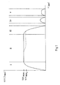
- the drawing shows a refueling process on the basis of a graph showing the volume flow V (t) changing over time t.
- the solid line indicates a refueling operation in which only one of several dispensing valves of the fluid delivery system is in use.
- the nozzle If the nozzle is fully opened, the lever of a fuel nozzle so completely pushed after inserting the tank nozzle into the tank opening of a vehicle, the value of the volumetric flow flowing through the piston diameter of 0 increases to the corresponding maximum value V (t) max.1 , see area I. If the dispensing valve then remains completely open, the result is a curve extending parallel to the X-axis (solid line), which is identified as region II. If the valve is then closed, the lever of the fuel nozzle is released, then the value of the volume flow flowing through the piston meter drops back to the value 0, see area III. Often, the nozzle is again carefully operated after the actual refueling process, in particular to correct the amount of money to be paid for the refueled fuel, see areas IV and V.
- V (t) max. 1 normally drops slightly, for example to V (t) max Dashed line in the areas II and III is indicated.
- the volumetric flow rate measuring device continuously detects actual volume flows of a fuel flowing through a new and thus properly functioning filter. Accordingly, there are five different graphs shown in the drawing.
- a desired volumetric flow range can now be defined which preferably contains all maximum volumetric flows V (t) max . plus corresponding tolerances, the tolerances are based in particular on empirical values.
- the set flow rate defines the volume flow range that represents a properly functioning filter.
- the specified nominal volumetric flow range is then stored in a memory of the central computer unit.
- a test interval is determined, for example, includes ten refueling operations.
- test interval As soon as within the test interval of ten refueling operations, an actual volumetric flow falls within the set volumetric flow range, this is an indication that the filter is functioning properly, therefore the test interval is reset and starts to run again.
- ten refueling operations in particular external influences are to be eliminated which lead to a low actual volumetric flow independently of the degree of clogging of the filter to be monitored. For example, it happens that a customer does not fully open the nozzle during a refueling process because he wants to fill only a small amount of fuel in the tank of his motor vehicle. In this way, the specified target volume flow range can not be achieved by the detected actual volume flows.
- test interval in the present example ten tank operations, it being assumed that at least one of the ten customers, the dispensing valve fully opens, so that the maximum ist-flow rate is achieved, with the proper functioning of the Filters should fall into the target volumetric flow range.
- a new set volume flow range is set again using the built-in new filter so that actual volume flows can again be detected and compared with the set volume flow range.
- the position of the filter within the fluid delivery system has not been precisely defined, since the position for the principle underlying the method according to the invention is essentially irrelevant. Depending on the position of the filter, although appropriate adjustments of the method may be required, which, however, are easy to carry out with knowledge of the present invention.
Landscapes
- Engineering & Computer Science (AREA)
- Mechanical Engineering (AREA)
- Chemical & Material Sciences (AREA)
- Combustion & Propulsion (AREA)
- General Engineering & Computer Science (AREA)
- Chemical Kinetics & Catalysis (AREA)
- Measuring Volume Flow (AREA)
- Loading And Unloading Of Fuel Tanks Or Ships (AREA)
- Flow Control (AREA)
Claims (23)
- Procédé pour déterminer un état de fonctionnement d'au moins un filtre traversé par un fluide, en particulier d'un filtre d'un système de transport de carburant, comprenant les étapes suivantes :- mesure de débits volumétriques réels- détermination d'au moins un débit volumétrique de consigne à l'aide de débits volumétriques réels d'un filtre fonctionnant correctement, qui sont relevés pendant un intervalle de détection prédéterminé, et- détermination de l'état de fonctionnement de l'au moins un filtre à partir d'une comparaison des débits volumétriques réels avec le débit volumétrique de consigne,caractérisé en ce que la détermination du débit volumétrique de consigne tient compte d'autres paramètres.
- Procédé selon la revendication 1, caractérisé en ce que l'intervalle de détection est défini par un nombre prédéterminé d'opérations de remplissage d'un réservoir, un intervalle de temps prédéterminé ou un volume transféré prédéterminé.
- Procédé selon l'une des revendications précédentes, caractérisé en ce que les autres paramètres comprennent le niveau de remplissage du réservoir de fluide et/ou la durée de remplissage du réservoir et/ou la distance entre la pompe de transfert du fluide et le réservoir de fluide et/ou le nombre de robinets de prélèvement et/ou des influences météorologiques.
- Procédé selon l'une des revendications précédentes, caractérisé en ce qu'une plage de tolérance est déterminée à partir du débit volumétrique de consigne.
- Procédé selon l'une des revendications précédentes, caractérisé en ce que le débit volumétrique de consigne et, lorsqu'elle est déterminée, la plage de tolérance sont enregistrés dans une unité de mémoire.
- Procédé selon l'une des revendications précédentes, caractérisé en ce que lors de la détection des débits volumétriques réels, d'autres paramètres sont captés, en particulier la durée de remplissage du réservoir et/ou le niveau de remplissage du réservoir de fluide et/ou la distance entre la pompe de transfert du fluide et le réservoir de fluide et/ou le nombre de robinets de prélèvement et/ou des météorologiques.
- Procédé selon l'une des revendications précédentes, caractérisé en ce que la détermination du débit volumétrique de consigne, la mesure des débits volumétriques réels, la comparaison des débits volumétriques et la détermination de l'état de fonctionnement de l'au moins un filtre sont effectuées à l'aide d'unités de calcul séparées dans l'espace et/ou d'une unité de calcul centrale.
- Procédé selon l'une des revendications précédentes, caractérisé en ce qu'un signal est émis lorsque les débits volumétriques réels captés n'atteignent pas le débit volumétrique de consigne déterminé dans un intervalle de contrôle prédéterminé.
- Procédé selon la revendication 8, caractérisé en ce que l'intervalle de contrôle est défini par un nombre prédéterminé d'opérations de remplissage du réservoir, un intervalle de temps prédéterminé ou un volume transféré prédéterminé.
- Procédé selon la revendication 8 ou 9, caractérisé en ce que l'intervalle de contrôle recommence au début à chaque fois que le débit volumétrique de consigne déterminé est atteint.
- Système de transfert de fluide, en particulier système de transfert de carburant, avec au moins un filtre, au moins un dispositif de mesure du débit volumétrique pour la détection d'un débit volumétrique du fluide traversant le filtre et une électronique d'évaluation conçue pour exécuter le procédé selon l'une des revendications précédentes, caractérisé en ce que le système comprend au moins un capteur pour détecter les autres paramètres.
- Système de transfert de fluide selon la revendication 11, caractérisé en ce que l'électronique d'analyse comprend au moins une unité de calculateur reliée à un dispositif de mesure du débit volumétrique de façon à échanger des données..
- Système de transfert de fluide selon la revendication 12, caractérisé en ce que l'au moins une unité de calcul comprend une unité de mémoire pour l'enregistrement d'un débit volumétrique de consigne.
- Système de transfert de fluide selon les revendications 11 à 13, caractérisé en ce que l'électronique d'analyse comprend une unité de calcul centrale qui est reliée à au moins un dispositif de mesure du débit volumétrique ou à au moins une unité de calcul pour échanger des données.
- Système de transfert de fluide selon la revendication 14, caractérisé en ce que l'unité de calcul centrale comprend une unité de mémoire pour l'enregistrement d'un débit volumétrique de consigne.
- Système de transfert de fluide selon l'une des revendications 11 à 15, caractérisé en ce que le système comprend un ou plusieurs dispositifs de distribution de fluide.
- Système de transfert de fluide selon la revendication 16, caractérisé en ce que chaque dispositif de distribution de fluide comprend au moins un dispositif de mesure du débit volumétrique.
- Système de transfert de fluide selon la revendication 17, caractérisé en ce que le dispositif de mesure du débit volumétrique comprend une mémoire pour enregistrer un débit volumétrique de consigne.
- Système de transfert de fluide selon l'une des revendications 17 à 18, caractérisé en ce que chaque dispositif de distribution de fluide comprend au moins un robinet de prélèvement.
- Système de transfert de fluide selon l'une des revendications 16 à 19, caractérisé en ce que le capteur détecte au moins comme autre paramètre le niveau de remplissage du réservoir de fluide et/ou la durée de remplissage du réservoir et/ou les influences météorologiques.
- Dispositif de mesure du débit volumétrique pour la mise en oeuvre du procédé selon l'une des revendications 1 à 10, caractérisé en ce qu'il comporte une unité de mémoire destinée à enregistrer un débit volumétrique de consigne.
- Dispositif de mesure du débit volumétrique selon la revendication 21, caractérisé en ce qu'il comprend une électronique d'évaluation conçue pour la mise en oeuvre du procédé selon l'une des revendications 1 à 10.
- Dispositif de mesure du débit volumétrique selon la revendication 21 ou 22, caractérisé en ce que le dispositif de mesure du débit volumétrique est conçu comme un compteur à piston.
Priority Applications (4)
| Application Number | Priority Date | Filing Date | Title |
|---|---|---|---|
| DE502006001888T DE502006001888D1 (de) | 2006-04-21 | 2006-04-21 | Verfahren zum Ermitteln eines Betriebszustandes eines von einem Fluid durchströmten Filters |
| EP06008279A EP1847708B1 (fr) | 2006-04-21 | 2006-04-21 | Procédé pour déterminer un état opérationnel d'un filtre passé par un fluide |
| RU2006125954/06A RU2351908C2 (ru) | 2006-04-21 | 2006-07-19 | Способ определения рабочего состояния фильтра для пропускания жидкости, система подачи жидкости и устройство измерения объемного расхода для осуществления указанного способа |
| UAA200608101A UA87125C2 (uk) | 2006-04-21 | 2006-07-19 | Спосіб визначення робочого стану фільтра для пропускання рідини |
Applications Claiming Priority (1)
| Application Number | Priority Date | Filing Date | Title |
|---|---|---|---|
| EP06008279A EP1847708B1 (fr) | 2006-04-21 | 2006-04-21 | Procédé pour déterminer un état opérationnel d'un filtre passé par un fluide |
Publications (2)
| Publication Number | Publication Date |
|---|---|
| EP1847708A1 EP1847708A1 (fr) | 2007-10-24 |
| EP1847708B1 true EP1847708B1 (fr) | 2008-10-22 |
Family
ID=36998231
Family Applications (1)
| Application Number | Title | Priority Date | Filing Date |
|---|---|---|---|
| EP06008279A Expired - Lifetime EP1847708B1 (fr) | 2006-04-21 | 2006-04-21 | Procédé pour déterminer un état opérationnel d'un filtre passé par un fluide |
Country Status (4)
| Country | Link |
|---|---|
| EP (1) | EP1847708B1 (fr) |
| DE (1) | DE502006001888D1 (fr) |
| RU (1) | RU2351908C2 (fr) |
| UA (1) | UA87125C2 (fr) |
Families Citing this family (1)
| Publication number | Priority date | Publication date | Assignee | Title |
|---|---|---|---|---|
| CN112856451A (zh) * | 2020-12-31 | 2021-05-28 | 台州市德长环保有限公司 | 一种废液处理系统及其处理方法 |
Family Cites Families (11)
| Publication number | Priority date | Publication date | Assignee | Title |
|---|---|---|---|---|
| SU1523753A1 (ru) * | 1986-09-22 | 1989-11-23 | Сибирский автомобильно-дорожный институт им.В.В.Куйбышева | Способ диагностировани фильтров |
| US4918426A (en) * | 1988-05-02 | 1990-04-17 | Amway Corporation | Method and apparatus for sensing fluid flow volume to indicate end of filter life |
| SU1550353A1 (ru) * | 1988-05-30 | 1990-03-15 | Подмосковный филиал Государственного союзного научно-исследовательского тракторного института | Способ диагностировани фильтра тонкой очистки топлива автотракторного дизел |
| SU1590572A1 (ru) * | 1988-10-17 | 1990-09-07 | Производственное Объединение "Коломенский Завод" | Сигнализатор загр зненности топливного и масл ного фильтров двигател внутреннего сгорани |
| RU2025416C1 (ru) * | 1992-04-07 | 1994-12-30 | Войсковая часть 75360 | Способ контроля засоренности фильтроэлементов топливных фильтров двигателей летательного аппарата |
| US5361216A (en) * | 1992-07-02 | 1994-11-01 | Progressive International Electronics | Flow signal monitor for a fuel dispensing system |
| JPH07275621A (ja) * | 1994-04-05 | 1995-10-24 | Nippon Oil Co Ltd | こし器の目詰まり度合い推定方法及び装置並びに目詰まり判定方法 |
| US5871651A (en) * | 1997-04-02 | 1999-02-16 | Gilbarco Inc. | Electronic filter status sensor |
| FR2787143B1 (fr) * | 1998-12-14 | 2001-02-16 | Magneti Marelli France | Detection de l'encrassement d'un filtre a carburant d'un circuit d'alimentation d'un moteur a combustion interne |
| SE515633C2 (sv) * | 2000-01-31 | 2001-09-17 | Abb Alstom Power Nv | Förfarande vid rensning av spärrfilter |
| SE523217C2 (sv) * | 2001-10-12 | 2004-04-06 | Dresser Wayne Ab | Anordning för bränselutmatningsenhet, bränsleutmatningsenhet, uppsättning delar för åstadkommande av en anordning för en bränsleutmatningsenhet, förfarande för åstadkommande av en lösgörbar filterenhet samt förfarande för byte av en filterenhet |
-
2006
- 2006-04-21 DE DE502006001888T patent/DE502006001888D1/de not_active Expired - Lifetime
- 2006-04-21 EP EP06008279A patent/EP1847708B1/fr not_active Expired - Lifetime
- 2006-07-19 RU RU2006125954/06A patent/RU2351908C2/ru not_active IP Right Cessation
- 2006-07-19 UA UAA200608101A patent/UA87125C2/uk unknown
Also Published As
| Publication number | Publication date |
|---|---|
| RU2006125954A (ru) | 2008-01-27 |
| UA87125C2 (uk) | 2009-06-25 |
| DE502006001888D1 (de) | 2008-12-04 |
| RU2351908C2 (ru) | 2009-04-10 |
| EP1847708A1 (fr) | 2007-10-24 |
Similar Documents
| Publication | Publication Date | Title |
|---|---|---|
| DE69902327T2 (de) | Kraftstoff-Abgabevorrichtung mit Dampfrückgewinnungsprüfung Möglichkeit | |
| DE69801483T2 (de) | Dampfrückgewinnungssystem für eine kraftstoffzapfanlage | |
| DE69523538T2 (de) | Messung einer Gaseigenschaft | |
| EP2781256B1 (fr) | Procédé d'actionnement d'un dispositif de dosage pour la distribution de fluides pouvant être pompés, notamment de préparation de pigments colorés, dispositif de dosage et bidon | |
| DE102017114665A1 (de) | Dosiereinrichtung u.a. | |
| WO2000012972A1 (fr) | Dispositif et procede de determination de volume | |
| DE112008001055T5 (de) | System und Verfahren zum Erfassen von Druckschwankungen in Kraftstoffzapfsäulen zum präziseren Messen der abgegebenen Kraftstoffmenge | |
| DE102013016773B4 (de) | Vorrichtung zur Temperiermedienversorgung und Verfahren zur Überwachung derselben | |
| DE102017123296A1 (de) | Fluidzuführbaugruppe zum Entfernen von Gasblasen aus einem Fluidpfad | |
| DE102006001866B4 (de) | Verfahren und Vorrichtung zur Abgabe eines Fluides aus einem Tank | |
| EP2539688B1 (fr) | Procédé et dispositif pour déterminer la qualité des résultats de mesure d'un appareil de mesure de lumière diffusée | |
| EP1686090A1 (fr) | Procédé pour l'acquisition de la quantité du carburant pendant l'avitaillement d'un véhicule | |
| DE3228265C2 (fr) | ||
| DE102010023742A1 (de) | Verfahren und Vorrichtung zum Erfassen von Flüssigkeit in einer Gasrückführungsleitung | |
| DE102004037064A1 (de) | Verfahren und Einrichtung zur Funktionsprüfung eines Feldgerätes vor dessen Erstinbetriebnahme | |
| EP1847708A1 (fr) | Procédé pour déterminer un état opérationnel d'un filtre passé par un fluide | |
| WO2019179763A1 (fr) | Procédé de fonctionnement d'un conteneur et conteneur | |
| EP2199754B1 (fr) | Procédé et dispositif de transmission d'un liquide contenant au moins ponctuellement une insufflation de gaz et de détermination de la quantité de liquide transmise | |
| EP4538581A1 (fr) | Procédé de fonctionnement d'un purgeur de condensat et purgeur de condensat | |
| EP2301800B1 (fr) | Dispositif de dépôt de milieux fluides à partir de chambres individuelles d'un véhicule à réservoir | |
| DE102006050634A1 (de) | Verfahren zum Bestimmen der Gasrückführrate an Zapfsäulen | |
| EP2995927A1 (fr) | Procede de determination d'une masse combustible et d'une densite de combustible | |
| EP0848204A2 (fr) | Procédé de contrÔle et de commande du chargement et déchargement de réservoirs sousterrains | |
| DE102018106790A1 (de) | Container sowie Verfahren zu dessen Betrieb | |
| EP1724032A2 (fr) | Procédé et dispositif pour surveiller une installation de nettoyage de récipients |
Legal Events
| Date | Code | Title | Description |
|---|---|---|---|
| GRAP | Despatch of communication of intention to grant a patent |
Free format text: ORIGINAL CODE: EPIDOSNIGR1 |
|
| PUAI | Public reference made under article 153(3) epc to a published international application that has entered the european phase |
Free format text: ORIGINAL CODE: 0009012 |
|
| 17P | Request for examination filed |
Effective date: 20070509 |
|
| AK | Designated contracting states |
Kind code of ref document: A1 Designated state(s): AT BE BG CH CY CZ DE DK EE ES FI FR GB GR HU IE IS IT LI LT LU LV MC NL PL PT RO SE SI SK TR |
|
| AX | Request for extension of the european patent |
Extension state: AL BA HR MK YU |
|
| GRAS | Grant fee paid |
Free format text: ORIGINAL CODE: EPIDOSNIGR3 |
|
| AKX | Designation fees paid |
Designated state(s): DE FR GB IT |
|
| GRAA | (expected) grant |
Free format text: ORIGINAL CODE: 0009210 |
|
| AK | Designated contracting states |
Kind code of ref document: B1 Designated state(s): DE FR GB IT |
|
| REG | Reference to a national code |
Ref country code: GB Ref legal event code: FG4D Free format text: NOT ENGLISH |
|
| REF | Corresponds to: |
Ref document number: 502006001888 Country of ref document: DE Date of ref document: 20081204 Kind code of ref document: P |
|
| PLBE | No opposition filed within time limit |
Free format text: ORIGINAL CODE: 0009261 |
|
| STAA | Information on the status of an ep patent application or granted ep patent |
Free format text: STATUS: NO OPPOSITION FILED WITHIN TIME LIMIT |
|
| 26N | No opposition filed |
Effective date: 20090723 |
|
| REG | Reference to a national code |
Ref country code: FR Ref legal event code: PLFP Year of fee payment: 10 |
|
| PGFP | Annual fee paid to national office [announced via postgrant information from national office to epo] |
Ref country code: DE Payment date: 20150417 Year of fee payment: 10 Ref country code: GB Payment date: 20150420 Year of fee payment: 10 |
|
| PGFP | Annual fee paid to national office [announced via postgrant information from national office to epo] |
Ref country code: IT Payment date: 20150427 Year of fee payment: 10 Ref country code: FR Payment date: 20150421 Year of fee payment: 10 |
|
| REG | Reference to a national code |
Ref country code: DE Ref legal event code: R119 Ref document number: 502006001888 Country of ref document: DE |
|
| GBPC | Gb: european patent ceased through non-payment of renewal fee |
Effective date: 20160421 |
|
| REG | Reference to a national code |
Ref country code: FR Ref legal event code: ST Effective date: 20161230 |
|
| PG25 | Lapsed in a contracting state [announced via postgrant information from national office to epo] |
Ref country code: DE Free format text: LAPSE BECAUSE OF NON-PAYMENT OF DUE FEES Effective date: 20161101 Ref country code: FR Free format text: LAPSE BECAUSE OF NON-PAYMENT OF DUE FEES Effective date: 20160502 Ref country code: GB Free format text: LAPSE BECAUSE OF NON-PAYMENT OF DUE FEES Effective date: 20160421 |
|
| PG25 | Lapsed in a contracting state [announced via postgrant information from national office to epo] |
Ref country code: IT Free format text: LAPSE BECAUSE OF NON-PAYMENT OF DUE FEES Effective date: 20160421 |