EP1847763B1 - Dispositif d'éclairage à plusieurs côtés avec anti-éblouissement - Google Patents
Dispositif d'éclairage à plusieurs côtés avec anti-éblouissement Download PDFInfo
- Publication number
- EP1847763B1 EP1847763B1 EP07104538A EP07104538A EP1847763B1 EP 1847763 B1 EP1847763 B1 EP 1847763B1 EP 07104538 A EP07104538 A EP 07104538A EP 07104538 A EP07104538 A EP 07104538A EP 1847763 B1 EP1847763 B1 EP 1847763B1
- Authority
- EP
- European Patent Office
- Prior art keywords
- housing
- assembly according
- lighting assembly
- openings
- lighting
- Prior art date
- Legal status (The legal status is an assumption and is not a legal conclusion. Google has not performed a legal analysis and makes no representation as to the accuracy of the status listed.)
- Not-in-force
Links
- 230000004313 glare Effects 0.000 title description 6
- 238000005286 illumination Methods 0.000 title description 4
- 230000005855 radiation Effects 0.000 claims abstract description 17
- 239000011521 glass Substances 0.000 claims description 7
- 238000001228 spectrum Methods 0.000 claims description 6
- NIXOWILDQLNWCW-UHFFFAOYSA-N acrylic acid group Chemical group C(C=C)(=O)O NIXOWILDQLNWCW-UHFFFAOYSA-N 0.000 claims description 4
- 239000000463 material Substances 0.000 claims description 4
- 239000004033 plastic Substances 0.000 claims description 2
- 239000004417 polycarbonate Substances 0.000 claims description 2
- 229920000515 polycarbonate Polymers 0.000 claims description 2
- 230000009970 fire resistant effect Effects 0.000 claims 1
- 230000006378 damage Effects 0.000 description 3
- 208000027418 Wounds and injury Diseases 0.000 description 2
- 238000011109 contamination Methods 0.000 description 2
- 208000014674 injury Diseases 0.000 description 2
- 239000002184 metal Substances 0.000 description 2
- 230000003595 spectral effect Effects 0.000 description 2
- 239000012780 transparent material Substances 0.000 description 2
- 240000006829 Ficus sundaica Species 0.000 description 1
- 230000000712 assembly Effects 0.000 description 1
- 238000000429 assembly Methods 0.000 description 1
- 238000005266 casting Methods 0.000 description 1
- 239000012141 concentrate Substances 0.000 description 1
- 230000001419 dependent effect Effects 0.000 description 1
- 238000009826 distribution Methods 0.000 description 1
- 239000000428 dust Substances 0.000 description 1
- 230000003670 easy-to-clean Effects 0.000 description 1
- 230000000694 effects Effects 0.000 description 1
- 230000002349 favourable effect Effects 0.000 description 1
- 239000003063 flame retardant Substances 0.000 description 1
- 239000011888 foil Substances 0.000 description 1
- 239000012535 impurity Substances 0.000 description 1
- 238000007689 inspection Methods 0.000 description 1
- 238000012423 maintenance Methods 0.000 description 1
- 238000004519 manufacturing process Methods 0.000 description 1
- 230000013011 mating Effects 0.000 description 1
- 239000011022 opal Substances 0.000 description 1
- 230000008447 perception Effects 0.000 description 1
- 238000003825 pressing Methods 0.000 description 1
- 239000000725 suspension Substances 0.000 description 1
Images




Classifications
-
- F—MECHANICAL ENGINEERING; LIGHTING; HEATING; WEAPONS; BLASTING
- F21—LIGHTING
- F21V—FUNCTIONAL FEATURES OR DETAILS OF LIGHTING DEVICES OR SYSTEMS THEREOF; STRUCTURAL COMBINATIONS OF LIGHTING DEVICES WITH OTHER ARTICLES, NOT OTHERWISE PROVIDED FOR
- F21V5/00—Refractors for light sources
- F21V5/002—Refractors for light sources using microoptical elements for redirecting or diffusing light
-
- F—MECHANICAL ENGINEERING; LIGHTING; HEATING; WEAPONS; BLASTING
- F21—LIGHTING
- F21V—FUNCTIONAL FEATURES OR DETAILS OF LIGHTING DEVICES OR SYSTEMS THEREOF; STRUCTURAL COMBINATIONS OF LIGHTING DEVICES WITH OTHER ARTICLES, NOT OTHERWISE PROVIDED FOR
- F21V21/00—Supporting, suspending, or attaching arrangements for lighting devices; Hand grips
- F21V21/005—Supporting, suspending, or attaching arrangements for lighting devices; Hand grips for several lighting devices in an end-to-end arrangement, i.e. light tracks
-
- F—MECHANICAL ENGINEERING; LIGHTING; HEATING; WEAPONS; BLASTING
- F21—LIGHTING
- F21V—FUNCTIONAL FEATURES OR DETAILS OF LIGHTING DEVICES OR SYSTEMS THEREOF; STRUCTURAL COMBINATIONS OF LIGHTING DEVICES WITH OTHER ARTICLES, NOT OTHERWISE PROVIDED FOR
- F21V3/00—Globes; Bowls; Cover glasses
- F21V3/04—Globes; Bowls; Cover glasses characterised by materials, surface treatments or coatings
-
- F—MECHANICAL ENGINEERING; LIGHTING; HEATING; WEAPONS; BLASTING
- F21—LIGHTING
- F21V—FUNCTIONAL FEATURES OR DETAILS OF LIGHTING DEVICES OR SYSTEMS THEREOF; STRUCTURAL COMBINATIONS OF LIGHTING DEVICES WITH OTHER ARTICLES, NOT OTHERWISE PROVIDED FOR
- F21V21/00—Supporting, suspending, or attaching arrangements for lighting devices; Hand grips
- F21V21/10—Pendants, arms, or standards; Fixing lighting devices to pendants, arms, or standards
- F21V21/112—Fixing lighting devices to pendants
-
- F—MECHANICAL ENGINEERING; LIGHTING; HEATING; WEAPONS; BLASTING
- F21—LIGHTING
- F21Y—INDEXING SCHEME ASSOCIATED WITH SUBCLASSES F21K, F21L, F21S and F21V, RELATING TO THE FORM OR THE KIND OF THE LIGHT SOURCES OR OF THE COLOUR OF THE LIGHT EMITTED
- F21Y2103/00—Elongate light sources, e.g. fluorescent tubes
Definitions
- the invention relates to a lighting arrangement comprising a housing, a lamp arranged in the housing, the radiation of which emerges from the housing through a plurality of housing openings, and means for deblasting this radiation, wherein at least one housing opening is arranged laterally and one housing opening is arranged downward.
- Interior lighting arrangements are usually either integrated into the wall or ceiling, provided thereon or suspended from the ceiling as pendant lights.
- the pendant lights usually have a cuboid, downwardly open housing.
- the suspension is attached to the top or ends of the housing.
- the light exits the downward opening from the housing.
- the opening is provided with fins.
- GB 713115 A is a lighting arrangement for an electric lantern disclosed.
- On one or both sides of the light source prismatic plates are arranged, which break the light by a division in the upper area downwards and reflect in the lower area.
- the down-facing lantern floor is either open or closed by a clear or transparent material.
- the lamp housing consists in principle of a cover plate on which the prismatic plates are clamped laterally by mounting bracket.
- the housing openings are closed with a transparent cover, which is profiled on the outside with a microstructure, the microstructure in turn is provided with a transparent, smooth cover, wherein the microstructure is designed blinding.
- the microstructure is designed in such a way that the angular range visible to persons is glare-free.
- the radiation not only goes down but into any desired angular range.
- the resulting glare is avoided by using a cover with a microstructure.
- smooth cover is provided on the profile. This additional cover is easy to clean and does not dirty easily. It is still manageable without risk of injury.
- the housing openings may extend along the majority of the side areas and downwards and the covers are arranged in frame parts. By using the profiled covers no glare can occur even with very large light exit openings.
- the housing may have a rectangular cross section, of which both sides and the lower portion form housing openings, which are covered by flat plates with profiled surface.
- the housing may also have a polygonal, oval or circular cross section.
- the housing can be tapered at the ends, the Gapuruse can be designed arcuate or graded stairs.
- the covers are made of pressed acrylic or glass.
- the cover may also be made of rolled material or foils. Made of pressed acrylic, the profile can be produced with the greatest precision.
- the covers can also consist of a fire-retardant plastic, in particular polycarbonate.
- the microstructures may be microprisms, in particular outwardly projecting microprisms.
- a microprism has dimensions in the range of a few tenths of a millimeter.
- pressed, linear or crossed structures are possible.
- the opening angle of the prisms or linear structures varies over the height of the opening.
- the laterally radiated radiation can be directed specifically in a preferred angular range.
- Other angular ranges are illuminated only slightly or not at all. In this way, on the one hand glare, on the other hand, an improved lighting in the desired direction.
- the housing comprises two end parts, which are connected to each other via frame parts, wherein the frame parts are held by parallel to the end portions extending, planar frames in addition in their position.
- the frame parts are profiled struts that have the same cross section over the entire length. This allows a cost-effective production.
- the frames may be inserted in slots or grooves provided in the struts perpendicular to their longitudinal axis.
- the light source to For example, a fluorescent lamp, can be passed through a recess in the frames.
- the end part has an opening into which connecting elements can be inserted.
- the fasteners can then be snapped or clamped. These fasteners can be variably selected.
- different connecting elements are used in the same housing. This creates a modular system that can be easily adapted to the requirements.
- the connecting elements can be connected to one another in an articulated manner and / or with fastening devices. Then several lights can be connected together.
- the connection angle is variable.
- a light source can have a spectrum with particularly high intensity in the short-wave spectral range and another light source can have a spectrum with particularly high intensity in the longer-wave spectral range. Then, for example, the light may be varied between a cold, rather blue spectrum corresponding to a high radiation temperature and a warm, rather red spectrum corresponding to a low radiation temperature.
- FIG.1 an exploded view of a modular lighting arrangement 10 is shown.
- Fig.2 is a cross section and in Figure 3 a longitudinal section through the arrangement shown.
- Figure 4 and 5 show the arrangement in assembled condition.
- like parts are given the same reference numerals.
- the lighting assembly comprises a housing 12.
- the housing 12 includes two parallel planar end portions 14 and 16.
- the end portions 14 and 16 are square and parallel.
- connecting struts 18, 20, 22 and 24 are inserted.
- the connecting struts are slightly longer than a fluorescent lamp of normal size. They connect the end parts 14 and 16.
- microprism plates described in more detail below. In Fig. 1 only one lateral microprism plate 32 is indicated.
- the upper opening 34 is covered by a metallic cover 36.
- a fluorescent lamp 40 On the bottom of a fluorescent lamp 40 is attached.
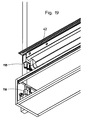
- the cover 36 is provided in the lateral areas 42 with a plurality of parallel slots through which light can also escape (see also Figure 19 ).
- the cover of the opaque material of the rest of the housing for example, chromed metal or the like.
- the top of the cover is screwed centrally with another, transparent, opal cover 44 with the rest of the housing. For this purpose, screws 43 are provided. This allows expansion of the cover in both directions when heated.
- At the ends of the cover control holes 45 are provided. The control holes 45 facilitate the removal of the cover, for example, during maintenance.
- Corresponding holes 47 are provided in the cover 36.
- the end parts 14 and 16 are provided with vertical, rectangular slots 46 (see also Figure 7 ). In the slots a cuboid projection 48 can be inserted, which sits on a connecting part 50.
- the connecting part has a vertical bore into which a tube 52 can be inserted. With the tube 52, the lamp is attached to a ceiling, for example. In the tube 52, the electrical leads for the supply of the light bulb are housed.
- the slot 46 has on the inside in the lower edge and a projecting, roof-shaped profile 49.
- the connecting part 50 has a corresponding profile 51, which in Fig. 8 is also recognizable.
- the connecting part 50 is inserted in the assembly in the slot 46, so that the profiles are positively against each other.
- a retractable screw is inserted through a corresponding threaded hole 53 into the profile 51 (FIG. Fig. 7 and 8th ) screwed. The screw fixed in this way the connecting part in its position.
- the struts 18, 20, 22 and 24 are provided with slots 60 into which ribs (support inserts) 54 made of metal or a transparent material are used. This is in cross section in Fig.2 and in the detail view in Fig. 6 again shown in more detail.
- the struts 18, 20, 22 and 24 are provided with circular projections 56 which extend in the direction of the illuminant.
- the projections 56 have a central bore 58.
- Slots 60 along the strut 18 serve as a receptacle for the frames 54.
- the frames 54 are flat and lie in a plane transverse to the connecting struts. They have four lugs 62, 64, 66 and 68 which extend in the direction of the connecting struts.
- Each of the flags is provided at its end with a bore which corresponds in the installed state with the bore 58 of the connecting strut 18.
- a wire or pipe threaded through the holes holds the frames and tie bars together.
- the frames 54 are rotatably mounted about axes 55. This facilitates the assembly.
- the covers 70 and the microprism plates 72 are ground on the outer edges 74. This is in Figure 6 shown.
- the connecting struts and the end pieces 14 and 16 have a corresponding profile. This facet cut is especially designed at the end pieces so that tolerances due to the different expansion coefficients of the materials is compensated. It is considered that the end pieces must have greater tolerances due to the greater extent in this direction.
- the circumferential facet grinding allows the positive engagement between the plates and the castings (end parts) or the struts and the end parts.
- the covers are held in position.
- the side housing openings and the downwardly oriented housing opening are covered in this way with glass plates 70.
- On the inside of the glass plates 70 each micro prism plates 72 are arranged.
- the microprism plates 72 are pressed from acrylic. They have a plurality of microprisms projecting outwardly towards the glass plate 70.
- the glass plate protects according to the projections from damage and contamination.
- a detail of such a micro prism plate 72 is shown in detail.
- the microprisms 71 are in the present embodiment of pyramidal projections, which are arranged directly next to each other.
- the deflection of a light beam is determined inter alia by the inclination angles ⁇ and ⁇ of the prism surfaces. It has been found that a ratio of the height of the microprisms to the overall height of the structure of 1: 3 is particularly favorable to produce.
- the microprisms are smaller than 2 mm and are produced with high quality by pressing.
- FIGS. 10 to 15 The effect of different angles on a laterally arranged micro prism plate is in the FIGS. 10 to 15 shown.
- Fig. 10 a section of a micro prism plate 73 is shown. The prisms have an opening angle 75 of 60 °.
- Fig. 10 is also shown a schematically illustrated illuminant 77.
- Figure 11 the course of the light rays 79 is shown. The light rays 79 are emitted from the microprism plate 73 Figure 10 distracted. It can be seen that in the configuration shown, within an observation angle 81 of 33.5 ° with respect to the horizontal 83, only very little radiation emerges, while the majority of the radiation concentrates in the steeply upwardly and downwardly directed areas. This avoids blinding observers in the more distant area.
- the room area below the luminaire eg a workplace, is well illuminated.
- the perception changes depending on the observer location.
- the observer entering a room sees little of the lamp and is not dazzled. The closer the observer gets to the lamp, the more it is illuminated.
- Fig. 12 and 13 an arrangement is shown in which the prism angle varies over the height of the illumination arrangement.
- a prism angle of 60 °.
- the prisms 89 are constructed asymmetrically. From the large angle 93, which is 98.4 °, only an angle 91 of 30 ° with respect to the horizontal 95 extends upward.
- the distribution of the asymmetrical prisms is 60 ° and 90 °.
- the associated beam path is in Fig. 13 shown. It can be seen that the middle region in Direction of the horizontal is completely debladed and practically no radiation in this angular range exits.
- Fig. 14 shows a micro prism plate 99 with unbalanced prisms. However, these are in contrast to the microprism plates after Fig. 10 to 13 inward, directed towards the bulb 101. In such an arrangement results in a course, as in Fig. 15 is shown. Again, there are areas 103 and 104 that are glare-free.
- the connecting struts 18, 20, 22 and 24 are provided on their end sides, each with an opening 78 in the longitudinal direction. In these openings 78 corresponding projections 76 are inserted on the inside of the end portions 14 and 16. This is best in Fig. 6 and 7 to see.
- the top cover rests on the case.
- the frames 66 are open at the top, as in Fig.2 is shown.
- the shape of the frames can be adapted to any cross-sectional shape. It is basically also changeable, which allows virtually any housing shapes.
- FIG. 7 is presented a first possibility of modular design.
- a connecting part 50 is inserted with a projection 48 in the manner already described.
- the connecting part 50 has a bore 80 into which a tube 52 (s. Fig.1 ) is introduced. With the tube 52, the light is fixed to the ceiling.
- FIG. 8 and Fig. 16-18 an alternative possibility of the modular design is shown.
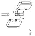
- two connecting parts 82 and 84 of two different lighting elements (not shown) are fastened to the same tube 52.
- the tube 52 is inserted into a two-part sleeve 86.
- the sleeve protrudes through holes 88 and 90 in the connecting parts 82 and 84.
- the connecting parts 82 and 84 each have two recesses 92 and 94, in which engage the thus projecting parts 96 and 98 of the other connecting part. This is in Fig. 18 shown.
- the sleeve portions 104 and 106 of the sleeve 86 each have an opening 108 and 110, respectively (FIG. Figure 17 . Figure 18 ).
- a pin 112 or 114 is provided below the opening 110 or above the opening 108.
- each sleeve part 104 or 106 is fixed in its position relative to the connecting parts 82 and 84, respectively.
- the sleeve parts 104 and 106 are rotatable against each other.
- the opening 110 is always aligned in the direction of the connecting part 82.
- the opening 108 is always aligned in the direction of the connecting part 84. Both connecting parts are rotated against each other and the openings always remain aligned.
- the supply line for the lighting arrangement is placed. This is electrically connected to a three-part socket 116.
- the bushing 116 is in Fig. 19 shown in detail.
- the cover with the fluorescent tube has mating connectors 118. By simply plugging the cover so the electrical contact can be made.
- the sockets of the luminous means are provided in the cover, which is provided between two connecting struts. The socket is thus not arranged in the end parts.
- the supply line can be guided directly through the connecting part to the socket 116.
- linear, crossed and angled lamp assemblies can be created in a similar manner.
- the desired illumination profiles can be generated.
- certain angular ranges can be blended and the light can be directed to other areas.
- the opening angle 100 of the microprisms 102 is variable over the height of the opening. The opening angles are chosen so that the angular range from which can be seen in the light is blinding. The radiation is directed so that it falls into other angular ranges.
- the glass plates or the back of the profiled plate can be engraved with letters or screen-printed.
- the lighting arrangement is also suitable for attachment to the wall. Then the tubes 52 and possibly connecting parts are not required.
Landscapes
- Engineering & Computer Science (AREA)
- General Engineering & Computer Science (AREA)
- Non-Portable Lighting Devices Or Systems Thereof (AREA)
- Vessels And Coating Films For Discharge Lamps (AREA)
- Fastening Of Light Sources Or Lamp Holders (AREA)
Claims (11)
- Disposition d'éclairage (10) munie d'un boîtier (12), d'une lampe (40) disposée dans le boîtier et dont le faisceau sort du boîtier par plusieurs orifices de boîtier (26, 28, 30) et des moyens (72) anti-éblouissement de ce faisceau, au moins un orifice de boîtier (26, 28) étant disposé latéralement et un orifice de boîtier (30) étant disposé vers le bas, l'orifice de boîtier latéral et celui dirigé vers le bas étant fermé chacun par un recouvrement transparent (72) dont au moins un recouvrement latéral et le recouvrement dirigé vers le bas sont profilés d'une microstructure (102) sur la face extérieure, la microstructure quant à elle est pourvue d'un recouvrement lisse, transparent (70),(a) la microstructure présente une configuration anti-éblouissement de sorte que le domaine angulaire visible pour les personnes est anti-éblouissant, et(b) le boîtier est formé de barres de liaison profilées et de deux éléments terminaux, les barres de liaison reliant les éléments terminaux l'un à l'autre de sorte que les recouvrements sont maintenus en place entre les barres de liaisons dans le profilé des barres de liaison.
- Disposition d'éclairage selon la revendication 1, caractérisée en ce que les orifices de boîtier s'étendent le long de l'élément principal des domaines latéraux ainsi que vers le bas, et les recouvrements sont disposés dans un ou plusieurs éléments de cadre formés par les barres de liaison.
- Disposition d'éclairage selon la revendication 2, caractérisée en ce que le boîtier présente une section transversale rectangulaire dont les deux côtés et la section inférieure forment des orifices de boîtier qui sont recouverts de plaques planes à surface profilée (72).
- Disposition d'éclairage selon l'une quelconque des revendications précédentes, caractérisée en ce que les recouvrements (72) sont en verre acrylique ou en verre pressé.
- Disposition d'éclairage selon l'une quelconque des revendications 1 à 3, caractérisée en ce que les recouvrements (70, 72) se composent d'un plastique ignifuge, notamment en polycarbonate.
- Disposition d'éclairage selon l'une des revendications précédentes, caractérisée en ce que les microstructures sont des microprismes (102).
- Disposition d'éclairage selon la revendication 3, caractérisée en ce que les plaques de recouvrement des orifices de boîtier latéraux présentent une surface munie d'un profil composé de prismes saillants vers l'extérieur ou de lamelles linéaires, l'angle d'ouverture (100) des prismes ou des lamelles linéaires variant en fonction de la hauteur d'ouverture.
- Disposition d'éclairage selon l'une des revendications précédentes, caractérisée en ce que les éléments terminaux (14, 16) sont reliés ensemble par des éléments de cadre (18, 20, 22, 24) formés par les barres de liaison, les éléments de cadre étant maintenus en plus en place par des membrures (54) planes parallèles aux éléments terminaux.
- Disposition d'éclairage selon la revendication 8, caractérisée en ce que l'élément terminal (14, 16) présente un orifice (46) dans lequel peuvent s'enclencher des éléments de liaison (50).
- Disposition d'éclairage selon la revendication 9, caractérisée en ce que les moyens de liaison (82, 84) peuvent être reliés ensemble en s'articulant et/ou à l'aide de dispositifs de fixation (52).
- Disposition d'éclairage selon l'une quelconque des revendications précédentes, caractérisée en ce qu'il est prévu plusieurs lampes à spectres de longueurs d'ondes différentes ainsi que des moyens de commande permettant de régler les intensités de rayonnement de chacune des lampes.
Applications Claiming Priority (1)
| Application Number | Priority Date | Filing Date | Title |
|---|---|---|---|
| DE102006019194A DE102006019194A1 (de) | 2006-04-21 | 2006-04-21 | Mehrseitige Beleuchtungsanordnung mit Entblendung |
Publications (2)
| Publication Number | Publication Date |
|---|---|
| EP1847763A1 EP1847763A1 (fr) | 2007-10-24 |
| EP1847763B1 true EP1847763B1 (fr) | 2010-04-28 |
Family
ID=38121796
Family Applications (1)
| Application Number | Title | Priority Date | Filing Date |
|---|---|---|---|
| EP07104538A Not-in-force EP1847763B1 (fr) | 2006-04-21 | 2007-03-21 | Dispositif d'éclairage à plusieurs côtés avec anti-éblouissement |
Country Status (5)
| Country | Link |
|---|---|
| US (1) | US7572034B2 (fr) |
| EP (1) | EP1847763B1 (fr) |
| CN (1) | CN101078478B (fr) |
| AT (1) | ATE466232T1 (fr) |
| DE (2) | DE102006019194A1 (fr) |
Families Citing this family (14)
| Publication number | Priority date | Publication date | Assignee | Title |
|---|---|---|---|---|
| DE102006019194A1 (de) * | 2006-04-21 | 2007-10-25 | Semperlux Ag - Lichttechnische Werke - | Mehrseitige Beleuchtungsanordnung mit Entblendung |
| DE202007011211U1 (de) * | 2007-08-10 | 2008-12-24 | Zumtobel Lighting Gmbh | Leuchte |
| DE202009002025U1 (de) | 2009-04-01 | 2009-05-28 | Semperlux Aktiengesellschaft - Lichttechnische Werke - | Beleuchtungsanordnung |
| US9976728B2 (en) | 2015-08-21 | 2018-05-22 | GE Lighting Solutions, LLC | Connector assembly for mounting lighting fixture |
| EP3086030A1 (fr) * | 2015-04-24 | 2016-10-26 | GE Lighting Solutions, LLC | Ensemble connecteur pour montage de luminaire |
| US9879845B2 (en) | 2016-01-07 | 2018-01-30 | Robert A. Sonneman | Modular lighting system using hangers and power bars |
| US10281126B2 (en) * | 2016-11-09 | 2019-05-07 | Contemporary Visions, LLC | Power bar hanger for modular lighting system |
| US10041662B2 (en) | 2016-11-09 | 2018-08-07 | Robert A. Sonneman | Light bar for a lighting system |
| US10359182B2 (en) | 2016-11-09 | 2019-07-23 | Contemporary Visions, LLC | Ring power bar hanger for modular lighting fixture |
| US10151466B2 (en) | 2016-11-09 | 2018-12-11 | Contemporary Visions, LLC | Laterally supported lights |
| US10184645B2 (en) | 2016-11-09 | 2019-01-22 | Contemporary Visions, LLC | Cylindrical housing for modular lighting system |
| US10174923B2 (en) | 2016-11-09 | 2019-01-08 | Contemporary Visions, LLC | Hanger for a modular lighting system having a main body with two channels to accommodate two segments of a power bar |
| US10865954B2 (en) | 2017-08-22 | 2020-12-15 | Signify Holding B.V. | Lighting system, lighting installation and ceiling installation |
| DE102018222327A1 (de) * | 2018-12-19 | 2020-06-25 | Frenger Systemen BV Heiz- und Kühltechnik GmbH | Strahlflächenaufbau mit Hochvolt-LEDs |
Family Cites Families (11)
| Publication number | Priority date | Publication date | Assignee | Title |
|---|---|---|---|---|
| GB713115A (en) | 1952-01-03 | 1954-08-04 | Crompton Parkinson Ltd | Improvements in electric lanterns |
| DE8711021U1 (de) * | 1987-08-10 | 1987-12-03 | Fa. August Gärtner, 1000 Berlin | Leuchte |
| US5839823A (en) * | 1996-03-26 | 1998-11-24 | Alliedsignal Inc. | Back-coupled illumination system with light recycling |
| JP3104870B2 (ja) * | 1998-01-29 | 2000-10-30 | スタンレー電気株式会社 | 自動車用ランプ |
| CN2401777Y (zh) * | 1999-08-24 | 2000-10-18 | 陈学智 | 投光灯上使用的透光灯罩 |
| DE10011257A1 (de) * | 1999-09-17 | 2001-03-22 | Siteco Beleuchtungstech Gmbh | Hohllichtleiterleuchte mit modularer Lichtauskoppeleinrichtung |
| TW504557B (en) * | 1999-11-29 | 2002-10-01 | Koninkl Philips Electronics Nv | Luminaire |
| US6851833B1 (en) * | 1999-12-10 | 2005-02-08 | Jerome H. Simon | Optical configurations for distributing radially collimated light |
| DE10201556A1 (de) * | 2002-01-17 | 2003-07-31 | Ludwig Leuchten Kg | Plattenleuchte |
| US20040195947A1 (en) * | 2003-04-04 | 2004-10-07 | Clark Jason Wilfred | High brightness LED fixture for replacing high intensity dishcharge (HID) lamps |
| DE102006019194A1 (de) * | 2006-04-21 | 2007-10-25 | Semperlux Ag - Lichttechnische Werke - | Mehrseitige Beleuchtungsanordnung mit Entblendung |
-
2006
- 2006-04-21 DE DE102006019194A patent/DE102006019194A1/de not_active Ceased
-
2007
- 2007-03-21 AT AT07104538T patent/ATE466232T1/de active
- 2007-03-21 EP EP07104538A patent/EP1847763B1/fr not_active Not-in-force
- 2007-03-21 DE DE502007003562T patent/DE502007003562D1/de active Active
- 2007-04-20 CN CN2007101266731A patent/CN101078478B/zh not_active Expired - Fee Related
- 2007-04-23 US US11/789,171 patent/US7572034B2/en not_active Expired - Fee Related
Also Published As
| Publication number | Publication date |
|---|---|
| CN101078478A (zh) | 2007-11-28 |
| EP1847763A1 (fr) | 2007-10-24 |
| ATE466232T1 (de) | 2010-05-15 |
| US20070247845A1 (en) | 2007-10-25 |
| CN101078478B (zh) | 2010-06-02 |
| DE102006019194A1 (de) | 2007-10-25 |
| DE502007003562D1 (de) | 2010-06-10 |
| HK1113401A1 (zh) | 2008-10-03 |
| US7572034B2 (en) | 2009-08-11 |
Similar Documents
| Publication | Publication Date | Title |
|---|---|---|
| EP1847763B1 (fr) | Dispositif d'éclairage à plusieurs côtés avec anti-éblouissement | |
| EP0898686B2 (fr) | Systeme d'eclairage muni d'un corps de base servant de support pour au moins une lampe | |
| DE202011104303U1 (de) | Aufnahmeprofil einer Leuchte | |
| EP1255950A1 (fr) | Appareil d'eclairage | |
| DE102009011794B4 (de) | Beleuchtungsanordnung mit Tragprofil | |
| EP3270047B1 (fr) | Appareil d'éclairage plat | |
| EP1495258A2 (fr) | Luminaire plat | |
| CH712778A2 (de) | Anordnung zur Lichtabgabe. | |
| DE3836611A1 (de) | Decken-einbauleuchte fuer eine paneeldecke | |
| EP2518389B1 (fr) | Élément optique longitudinal et agencement d'émission de lumière avec un élément optique | |
| DE9015308U1 (de) | Leuchte | |
| EP1843082B1 (fr) | Plafonnier, en particulier pour utilisation dans un couloir | |
| DE102004035461A1 (de) | Multifunktionale kompakte Leuchte | |
| EP2322734A2 (fr) | Plafond lumineux | |
| DE102004044024B4 (de) | Vorrichtung zur hängenden Anordung einer Leuchte | |
| EP1688666A2 (fr) | Boîtier ainsi que profilé pour boîtier | |
| DE202018101591U1 (de) | Leuchte | |
| DE2615107B2 (de) | Mittelstreifenleuchte für Richtungsfahrbahnen | |
| DE9301871U1 (de) | Leuchte | |
| DE3011478A1 (de) | Leuchte | |
| DE20108425U1 (de) | Beleuchtungseinheit mit einstellbarem Lichtkegel | |
| DE102004013059A1 (de) | Modulares Lichtsystem | |
| DE9108195U1 (de) | Leuchtender Rahmen für ein Bild oder einen Spiegel | |
| DE29605993U1 (de) | Lichterkette bzw. Lichtband | |
| DE9102156U1 (de) | Leuchte |
Legal Events
| Date | Code | Title | Description |
|---|---|---|---|
| PUAI | Public reference made under article 153(3) epc to a published international application that has entered the european phase |
Free format text: ORIGINAL CODE: 0009012 |
|
| 17P | Request for examination filed |
Effective date: 20070720 |
|
| AK | Designated contracting states |
Kind code of ref document: A1 Designated state(s): AT BE BG CH CY CZ DE DK EE ES FI FR GB GR HU IE IS IT LI LT LU LV MC MT NL PL PT RO SE SI SK TR |
|
| AX | Request for extension of the european patent |
Extension state: AL BA HR MK YU |
|
| AKX | Designation fees paid |
Designated state(s): AT BE BG CH CY CZ DE DK EE ES FI FR GB GR HU IE IS IT LI LT LU LV MC MT NL PL PT RO SE SI SK TR |
|
| 17Q | First examination report despatched |
Effective date: 20080728 |
|
| GRAP | Despatch of communication of intention to grant a patent |
Free format text: ORIGINAL CODE: EPIDOSNIGR1 |
|
| GRAS | Grant fee paid |
Free format text: ORIGINAL CODE: EPIDOSNIGR3 |
|
| GRAA | (expected) grant |
Free format text: ORIGINAL CODE: 0009210 |
|
| AK | Designated contracting states |
Kind code of ref document: B1 Designated state(s): AT BE BG CH CY CZ DE DK EE ES FI FR GB GR HU IE IS IT LI LT LU LV MC MT NL PL PT RO SE SI SK TR |
|
| REG | Reference to a national code |
Ref country code: GB Ref legal event code: FG4D Free format text: NOT ENGLISH |
|
| REG | Reference to a national code |
Ref country code: CH Ref legal event code: EP |
|
| REG | Reference to a national code |
Ref country code: IE Ref legal event code: FG4D Free format text: LANGUAGE OF EP DOCUMENT: GERMAN |
|
| REF | Corresponds to: |
Ref document number: 502007003562 Country of ref document: DE Date of ref document: 20100610 Kind code of ref document: P |
|
| REG | Reference to a national code |
Ref country code: NL Ref legal event code: VDEP Effective date: 20100428 |
|
| LTIE | Lt: invalidation of european patent or patent extension |
Effective date: 20100428 |
|
| PG25 | Lapsed in a contracting state [announced via postgrant information from national office to epo] |
Ref country code: SE Free format text: LAPSE BECAUSE OF FAILURE TO SUBMIT A TRANSLATION OF THE DESCRIPTION OR TO PAY THE FEE WITHIN THE PRESCRIBED TIME-LIMIT Effective date: 20100428 Ref country code: NL Free format text: LAPSE BECAUSE OF FAILURE TO SUBMIT A TRANSLATION OF THE DESCRIPTION OR TO PAY THE FEE WITHIN THE PRESCRIBED TIME-LIMIT Effective date: 20100428 Ref country code: ES Free format text: LAPSE BECAUSE OF FAILURE TO SUBMIT A TRANSLATION OF THE DESCRIPTION OR TO PAY THE FEE WITHIN THE PRESCRIBED TIME-LIMIT Effective date: 20100808 Ref country code: LT Free format text: LAPSE BECAUSE OF FAILURE TO SUBMIT A TRANSLATION OF THE DESCRIPTION OR TO PAY THE FEE WITHIN THE PRESCRIBED TIME-LIMIT Effective date: 20100428 |
|
| REG | Reference to a national code |
Ref country code: IE Ref legal event code: FD4D |
|
| PG25 | Lapsed in a contracting state [announced via postgrant information from national office to epo] |
Ref country code: SI Free format text: LAPSE BECAUSE OF FAILURE TO SUBMIT A TRANSLATION OF THE DESCRIPTION OR TO PAY THE FEE WITHIN THE PRESCRIBED TIME-LIMIT Effective date: 20100428 Ref country code: LV Free format text: LAPSE BECAUSE OF FAILURE TO SUBMIT A TRANSLATION OF THE DESCRIPTION OR TO PAY THE FEE WITHIN THE PRESCRIBED TIME-LIMIT Effective date: 20100428 Ref country code: IS Free format text: LAPSE BECAUSE OF FAILURE TO SUBMIT A TRANSLATION OF THE DESCRIPTION OR TO PAY THE FEE WITHIN THE PRESCRIBED TIME-LIMIT Effective date: 20100828 Ref country code: FI Free format text: LAPSE BECAUSE OF FAILURE TO SUBMIT A TRANSLATION OF THE DESCRIPTION OR TO PAY THE FEE WITHIN THE PRESCRIBED TIME-LIMIT Effective date: 20100428 |
|
| PG25 | Lapsed in a contracting state [announced via postgrant information from national office to epo] |
Ref country code: CY Free format text: LAPSE BECAUSE OF FAILURE TO SUBMIT A TRANSLATION OF THE DESCRIPTION OR TO PAY THE FEE WITHIN THE PRESCRIBED TIME-LIMIT Effective date: 20100519 Ref country code: PL Free format text: LAPSE BECAUSE OF FAILURE TO SUBMIT A TRANSLATION OF THE DESCRIPTION OR TO PAY THE FEE WITHIN THE PRESCRIBED TIME-LIMIT Effective date: 20100428 |
|
| PG25 | Lapsed in a contracting state [announced via postgrant information from national office to epo] |
Ref country code: IE Free format text: LAPSE BECAUSE OF FAILURE TO SUBMIT A TRANSLATION OF THE DESCRIPTION OR TO PAY THE FEE WITHIN THE PRESCRIBED TIME-LIMIT Effective date: 20100428 Ref country code: DK Free format text: LAPSE BECAUSE OF FAILURE TO SUBMIT A TRANSLATION OF THE DESCRIPTION OR TO PAY THE FEE WITHIN THE PRESCRIBED TIME-LIMIT Effective date: 20100428 Ref country code: EE Free format text: LAPSE BECAUSE OF FAILURE TO SUBMIT A TRANSLATION OF THE DESCRIPTION OR TO PAY THE FEE WITHIN THE PRESCRIBED TIME-LIMIT Effective date: 20100428 Ref country code: PT Free format text: LAPSE BECAUSE OF FAILURE TO SUBMIT A TRANSLATION OF THE DESCRIPTION OR TO PAY THE FEE WITHIN THE PRESCRIBED TIME-LIMIT Effective date: 20100830 Ref country code: GR Free format text: LAPSE BECAUSE OF FAILURE TO SUBMIT A TRANSLATION OF THE DESCRIPTION OR TO PAY THE FEE WITHIN THE PRESCRIBED TIME-LIMIT Effective date: 20100729 |
|
| PG25 | Lapsed in a contracting state [announced via postgrant information from national office to epo] |
Ref country code: SK Free format text: LAPSE BECAUSE OF FAILURE TO SUBMIT A TRANSLATION OF THE DESCRIPTION OR TO PAY THE FEE WITHIN THE PRESCRIBED TIME-LIMIT Effective date: 20100428 Ref country code: CZ Free format text: LAPSE BECAUSE OF FAILURE TO SUBMIT A TRANSLATION OF THE DESCRIPTION OR TO PAY THE FEE WITHIN THE PRESCRIBED TIME-LIMIT Effective date: 20100428 Ref country code: RO Free format text: LAPSE BECAUSE OF FAILURE TO SUBMIT A TRANSLATION OF THE DESCRIPTION OR TO PAY THE FEE WITHIN THE PRESCRIBED TIME-LIMIT Effective date: 20100428 |
|
| PLBE | No opposition filed within time limit |
Free format text: ORIGINAL CODE: 0009261 |
|
| STAA | Information on the status of an ep patent application or granted ep patent |
Free format text: STATUS: NO OPPOSITION FILED WITHIN TIME LIMIT |
|
| PG25 | Lapsed in a contracting state [announced via postgrant information from national office to epo] |
Ref country code: IT Free format text: LAPSE BECAUSE OF FAILURE TO SUBMIT A TRANSLATION OF THE DESCRIPTION OR TO PAY THE FEE WITHIN THE PRESCRIBED TIME-LIMIT Effective date: 20100428 |
|
| 26N | No opposition filed |
Effective date: 20110131 |
|
| BERE | Be: lapsed |
Owner name: SEMPERLUX AKTIENGESELLSCHAFT, LICHTTECHNISCHE WER Effective date: 20110331 |
|
| PG25 | Lapsed in a contracting state [announced via postgrant information from national office to epo] |
Ref country code: MC Free format text: LAPSE BECAUSE OF NON-PAYMENT OF DUE FEES Effective date: 20110331 |
|
| REG | Reference to a national code |
Ref country code: CH Ref legal event code: PL |
|
| REG | Reference to a national code |
Ref country code: FR Ref legal event code: ST Effective date: 20111130 |
|
| PG25 | Lapsed in a contracting state [announced via postgrant information from national office to epo] |
Ref country code: MT Free format text: LAPSE BECAUSE OF FAILURE TO SUBMIT A TRANSLATION OF THE DESCRIPTION OR TO PAY THE FEE WITHIN THE PRESCRIBED TIME-LIMIT Effective date: 20100428 Ref country code: BE Free format text: LAPSE BECAUSE OF NON-PAYMENT OF DUE FEES Effective date: 20110331 |
|
| PG25 | Lapsed in a contracting state [announced via postgrant information from national office to epo] |
Ref country code: CH Free format text: LAPSE BECAUSE OF NON-PAYMENT OF DUE FEES Effective date: 20110331 Ref country code: FR Free format text: LAPSE BECAUSE OF NON-PAYMENT OF DUE FEES Effective date: 20110331 Ref country code: LI Free format text: LAPSE BECAUSE OF NON-PAYMENT OF DUE FEES Effective date: 20110331 |
|
| REG | Reference to a national code |
Ref country code: DE Ref legal event code: R082 Ref document number: 502007003562 Country of ref document: DE Representative=s name: PATENTANWAELTE WEISSE & WOLGAST, DE |
|
| REG | Reference to a national code |
Ref country code: DE Ref legal event code: R081 Ref document number: 502007003562 Country of ref document: DE Owner name: SELUX AKTIENGESELLSCHAFT, DE Free format text: FORMER OWNER: SEMPERLUX AKTIENGESELLSCHAFT - LICHTTECHNISCHE WERKE -, 12277 BERLIN, DE Effective date: 20120919 Ref country code: DE Ref legal event code: R082 Ref document number: 502007003562 Country of ref document: DE Representative=s name: WEISSE, RENATE, DIPL.-PHYS. DR.-ING., DE Effective date: 20120919 Ref country code: DE Ref legal event code: R082 Ref document number: 502007003562 Country of ref document: DE Representative=s name: PATENTANWAELTE WEISSE & WOLGAST, DE Effective date: 20120919 |
|
| PGFP | Annual fee paid to national office [announced via postgrant information from national office to epo] |
Ref country code: GB Payment date: 20130325 Year of fee payment: 7 |
|
| REG | Reference to a national code |
Ref country code: AT Ref legal event code: MM01 Ref document number: 466232 Country of ref document: AT Kind code of ref document: T Effective date: 20120321 |
|
| PG25 | Lapsed in a contracting state [announced via postgrant information from national office to epo] |
Ref country code: LU Free format text: LAPSE BECAUSE OF NON-PAYMENT OF DUE FEES Effective date: 20110321 |
|
| PG25 | Lapsed in a contracting state [announced via postgrant information from national office to epo] |
Ref country code: AT Free format text: LAPSE BECAUSE OF NON-PAYMENT OF DUE FEES Effective date: 20120321 |
|
| REG | Reference to a national code |
Ref country code: DE Ref legal event code: R082 Ref document number: 502007003562 Country of ref document: DE Representative=s name: WEISSE, RENATE, DIPL.-PHYS. DR.-ING., DE |
|
| PG25 | Lapsed in a contracting state [announced via postgrant information from national office to epo] |
Ref country code: BG Free format text: LAPSE BECAUSE OF FAILURE TO SUBMIT A TRANSLATION OF THE DESCRIPTION OR TO PAY THE FEE WITHIN THE PRESCRIBED TIME-LIMIT Effective date: 20100728 Ref country code: TR Free format text: LAPSE BECAUSE OF FAILURE TO SUBMIT A TRANSLATION OF THE DESCRIPTION OR TO PAY THE FEE WITHIN THE PRESCRIBED TIME-LIMIT Effective date: 20100428 |
|
| PG25 | Lapsed in a contracting state [announced via postgrant information from national office to epo] |
Ref country code: HU Free format text: LAPSE BECAUSE OF FAILURE TO SUBMIT A TRANSLATION OF THE DESCRIPTION OR TO PAY THE FEE WITHIN THE PRESCRIBED TIME-LIMIT Effective date: 20100428 |
|
| GBPC | Gb: european patent ceased through non-payment of renewal fee |
Effective date: 20140321 |
|
| PG25 | Lapsed in a contracting state [announced via postgrant information from national office to epo] |
Ref country code: GB Free format text: LAPSE BECAUSE OF NON-PAYMENT OF DUE FEES Effective date: 20140321 |
|
| PGFP | Annual fee paid to national office [announced via postgrant information from national office to epo] |
Ref country code: DE Payment date: 20190930 Year of fee payment: 13 |
|
| REG | Reference to a national code |
Ref country code: DE Ref legal event code: R119 Ref document number: 502007003562 Country of ref document: DE |
|
| PG25 | Lapsed in a contracting state [announced via postgrant information from national office to epo] |
Ref country code: DE Free format text: LAPSE BECAUSE OF NON-PAYMENT OF DUE FEES Effective date: 20201001 |