EP1847785A1 - Appareil de chauffage - Google Patents
Appareil de chauffage Download PDFInfo
- Publication number
- EP1847785A1 EP1847785A1 EP07106363A EP07106363A EP1847785A1 EP 1847785 A1 EP1847785 A1 EP 1847785A1 EP 07106363 A EP07106363 A EP 07106363A EP 07106363 A EP07106363 A EP 07106363A EP 1847785 A1 EP1847785 A1 EP 1847785A1
- Authority
- EP
- European Patent Office
- Prior art keywords
- heat exchanger
- housing
- heater according
- heater
- heating unit
- Prior art date
- Legal status (The legal status is an assumption and is not a legal conclusion. Google has not performed a legal analysis and makes no representation as to the accuracy of the status listed.)
- Granted
Links
Images


Classifications
-
- H—ELECTRICITY
- H05—ELECTRIC TECHNIQUES NOT OTHERWISE PROVIDED FOR
- H05B—ELECTRIC HEATING; ELECTRIC LIGHT SOURCES NOT OTHERWISE PROVIDED FOR; CIRCUIT ARRANGEMENTS FOR ELECTRIC LIGHT SOURCES, IN GENERAL
- H05B3/00—Ohmic-resistance heating
- H05B3/40—Heating elements having the shape of rods or tubes
- H05B3/42—Heating elements having the shape of rods or tubes non-flexible
- H05B3/48—Heating elements having the shape of rods or tubes non-flexible heating conductor embedded in insulating material
- H05B3/50—Heating elements having the shape of rods or tubes non-flexible heating conductor embedded in insulating material heating conductor arranged in metal tubes, the radiating surface having heat-conducting fins
-
- F—MECHANICAL ENGINEERING; LIGHTING; HEATING; WEAPONS; BLASTING
- F24—HEATING; RANGES; VENTILATING
- F24H—FLUID HEATERS, e.g. WATER OR AIR HEATERS, HAVING HEAT-GENERATING MEANS, e.g. HEAT PUMPS, IN GENERAL
- F24H3/00—Air heaters
- F24H3/002—Air heaters using electric energy supply
-
- F—MECHANICAL ENGINEERING; LIGHTING; HEATING; WEAPONS; BLASTING
- F24—HEATING; RANGES; VENTILATING
- F24H—FLUID HEATERS, e.g. WATER OR AIR HEATERS, HAVING HEAT-GENERATING MEANS, e.g. HEAT PUMPS, IN GENERAL
- F24H3/00—Air heaters
- F24H3/02—Air heaters with forced circulation
- F24H3/04—Air heaters with forced circulation the air being in direct contact with the heating medium, e.g. electric heating element
- F24H3/0405—Air heaters with forced circulation the air being in direct contact with the heating medium, e.g. electric heating element using electric energy supply, e.g. the heating medium being a resistive element; Heating by direct contact, i.e. with resistive elements, electrodes and fins being bonded together without additional element in-between
- F24H3/0429—For vehicles
-
- F—MECHANICAL ENGINEERING; LIGHTING; HEATING; WEAPONS; BLASTING
- F24—HEATING; RANGES; VENTILATING
- F24H—FLUID HEATERS, e.g. WATER OR AIR HEATERS, HAVING HEAT-GENERATING MEANS, e.g. HEAT PUMPS, IN GENERAL
- F24H3/00—Air heaters
- F24H3/02—Air heaters with forced circulation
- F24H3/04—Air heaters with forced circulation the air being in direct contact with the heating medium, e.g. electric heating element
- F24H3/0405—Air heaters with forced circulation the air being in direct contact with the heating medium, e.g. electric heating element using electric energy supply, e.g. the heating medium being a resistive element; Heating by direct contact, i.e. with resistive elements, electrodes and fins being bonded together without additional element in-between
- F24H3/0429—For vehicles
- F24H3/0435—Structures comprising heat spreading elements in the form of fins
-
- F—MECHANICAL ENGINEERING; LIGHTING; HEATING; WEAPONS; BLASTING
- F24—HEATING; RANGES; VENTILATING
- F24H—FLUID HEATERS, e.g. WATER OR AIR HEATERS, HAVING HEAT-GENERATING MEANS, e.g. HEAT PUMPS, IN GENERAL
- F24H3/00—Air heaters
- F24H3/02—Air heaters with forced circulation
- F24H3/04—Air heaters with forced circulation the air being in direct contact with the heating medium, e.g. electric heating element
- F24H3/0405—Air heaters with forced circulation the air being in direct contact with the heating medium, e.g. electric heating element using electric energy supply, e.g. the heating medium being a resistive element; Heating by direct contact, i.e. with resistive elements, electrodes and fins being bonded together without additional element in-between
- F24H3/0429—For vehicles
- F24H3/0441—Interfaces between the electrodes of a resistive heating element and the power supply means
- F24H3/0447—Forms of the electrode terminals, e.g. tongues or clips
-
- F—MECHANICAL ENGINEERING; LIGHTING; HEATING; WEAPONS; BLASTING
- F24—HEATING; RANGES; VENTILATING
- F24H—FLUID HEATERS, e.g. WATER OR AIR HEATERS, HAVING HEAT-GENERATING MEANS, e.g. HEAT PUMPS, IN GENERAL
- F24H3/00—Air heaters
- F24H3/02—Air heaters with forced circulation
- F24H3/04—Air heaters with forced circulation the air being in direct contact with the heating medium, e.g. electric heating element
- F24H3/0405—Air heaters with forced circulation the air being in direct contact with the heating medium, e.g. electric heating element using electric energy supply, e.g. the heating medium being a resistive element; Heating by direct contact, i.e. with resistive elements, electrodes and fins being bonded together without additional element in-between
- F24H3/0429—For vehicles
- F24H3/0452—Frame constructions
-
- F—MECHANICAL ENGINEERING; LIGHTING; HEATING; WEAPONS; BLASTING
- F24—HEATING; RANGES; VENTILATING
- F24H—FLUID HEATERS, e.g. WATER OR AIR HEATERS, HAVING HEAT-GENERATING MEANS, e.g. HEAT PUMPS, IN GENERAL
- F24H9/00—Details
- F24H9/18—Arrangement or mounting of grates or heating means
- F24H9/1854—Arrangement or mounting of grates or heating means for air heaters
- F24H9/1863—Arrangement or mounting of electric heating means
- F24H9/1872—PTC resistor
-
- H—ELECTRICITY
- H05—ELECTRIC TECHNIQUES NOT OTHERWISE PROVIDED FOR
- H05B—ELECTRIC HEATING; ELECTRIC LIGHT SOURCES NOT OTHERWISE PROVIDED FOR; CIRCUIT ARRANGEMENTS FOR ELECTRIC LIGHT SOURCES, IN GENERAL
- H05B3/00—Ohmic-resistance heating
- H05B3/02—Details
- H05B3/06—Heater elements structurally combined with coupling elements or holders
-
- H—ELECTRICITY
- H05—ELECTRIC TECHNIQUES NOT OTHERWISE PROVIDED FOR
- H05B—ELECTRIC HEATING; ELECTRIC LIGHT SOURCES NOT OTHERWISE PROVIDED FOR; CIRCUIT ARRANGEMENTS FOR ELECTRIC LIGHT SOURCES, IN GENERAL
- H05B2203/00—Aspects relating to Ohmic resistive heating covered by group H05B3/00
- H05B2203/02—Heaters using heating elements having a positive temperature coefficient
Definitions
- the invention relates to a heater according to the preamble of claim 1.
- Such heaters are widely used, e.g. In control cabinets, to keep the electronics contained therein at low outside temperatures to operating temperature. They are manufactured with different heat outputs in high quantities. The price accepted in the market is relatively low.
- the invention is therefore based on the object to keep the manufacturing and assembly costs for heaters of the type mentioned as low as possible.
- a heater comprising a heat exchanger, a heating unit, which is arranged in a receiving cavity of the heat exchanger, and a housing in which the heat exchanger is mounted, characterized in that plastic moldings, on the one hand fixing means for clamping fixing the Plastic moldings on end faces of the heat exchanger and on the other hand guide means which are in positive engagement with counter guide means on the housing.
- An essential point of the invention thus lies in the fact that the heater can be easily and quickly mounted by simple mating and positive insertion with few manufacturing steps.
- the heat exchanger is formed as an extruded profile and the extruded profile in the strand direction has continuous recesses into which formed as bendable extensions fixing the plastic moldings are used under elastic deformation.
- the through recesses are formed in pairs and the receiving cavity between them and formed substantially symmetrically to these, which has the advantage that the plastic molding can be formed symmetrically.
- the assembly is further facilitated if advantageously the guide and the counter guide devices are arranged as tongue and groove devices such that the heat exchanger from one direction into a U-shaped base of the housing can be inserted. Thereby, the heat exchanger can be inserted in a manufacturing step from above into the housing until it touches the bottom of the base.
- Such a U-shaped base is preferably obtained by virtue of the fact that the base preferably has a base plate and two grid walls arranged at a distance from one another, on whose inner surfaces the counter guide devices are preferably arranged centrally. Due to the central arrangement of the counter guide devices is given a defined position for the insertion and insertion of the heat exchanger, whereby the production is further facilitated.
- the housing has a cover with a U-shaped hood in cross-section, which is designed such that it surrounds the grid walls with end cap edges or adjoins this, to form a permeable through the lattice walls cavity.
- a cover with a U-shaped hood in cross-section which is designed such that it surrounds the grid walls with end cap edges or adjoins this, to form a permeable through the lattice walls cavity.
- the hood preferably has further fixing means for mutually connecting the mesh walls with each other, the further fixing engage in locking pieces of the mesh walls, which safely and permanently engage each other without further manufacturing effort and the heat exchanger and the lid hold in a defined position.
- the cover comprises a cover portion, which covers the closed housing mounted on the base clamps, which eliminates additional effort for a safe power supply.
- the hood is preferably lined with a metal sheet or a sheet of heat-reflecting material.
- the housing forms a chimney to form a convection flow through the heat exchanger
- directed heat flow to an object to be heated is achieved with good efficiency.
- the housing is designed as a plastic injection molded part, because characterized in one operation, all necessary structural parts, such as grid formation, counter guide devices, lattice wall strips, locking pieces, lugs, moldings, etc. are formed.
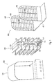
- the heater not yet mounted has a heat exchanger 200 and a housing 600 which consists of a base 400 with two grid walls 402,403 arranged in a spaced relationship and a hood-shaped cover 500.
- a heating unit 300 is used, which is in particular equipped with PTC elements (see FIG. 4), wherein surfaces of the receiving cavity 206 are pressed against surfaces of the heating unit 300 in order to obtain a good heat transfer.
- the receiving cavity 206 is closed at both ends of the heat exchanger 200, each with a plastic molding 100, which is equipped with a guide device 109.
- the plastic molded parts 100 lines 311.312 for power supply means 303 of the heating unit 300 (see Fig.
- the grid walls 402, 403 have counter guide means 404, 405 arranged centrally on inner sides, which engage in the guide means 109 when the heater is mounted.
- the housing 600 is closed with the hood-shaped cover 500 to form a cavity through which the mesh walls 402,403 can flow.
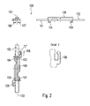
- the plastic molded part 100 according to FIG. 2 has the shape of a strip and has a first pair of bendable extensions 104, 105 and, spaced from the other end, a second pair of bendable further extensions on one strip surface 101 as fixing devices 104, 105, 106, 107 106,107, wherein the extensions of a pair each spaced from a center line 103 of the plastic molded part 100 extend to the edge of the plastic molding 100, so that a total of four fixing devices 104,105,106,107 are formed.
- the extensions of the first pair and the further extensions of the second pair are angled to each other.
- the openings have to one side and to the other end and through which the lines 12,13 for the power supply means 303 are led to the outside (see Fig. 3).
- On the other strip surface 102 is formed as a guide means a longitudinal groove (109).
- the plastic molded part 100 is formed symmetrically.
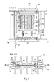
- the heat exchanger 200 includes a heat exchanger body 201 having fins forming a first surface 203 for exchanging heat between the heat exchanger body 201 and the ambient air or other fluid medium.
- a second surface 204 is arranged, which faces a pressure surface 205.
- This pressure surface 205 is formed by a pressure element 202, which in the present embodiment is identical to Heat exchanger body 201 is formed; the heating unit 300 thus sits between two identical heat exchanger bodies 201,202 so that optimum heat dissipation is ensured.
- the heating unit 300 is located between the second surface 204 and the pressure surface 205 after insertion into the receiving cavity 206.
- the second surface 204 and the pressing surface 205 are identically shaped and formed so as to fully fit surfaces of the heating unit 300.
- recesses 207 are provided in which in the receiving cavity 206 projecting further ribs 208 are provided as further guide means with the heating unit 300 cooperate such that the heating unit 300 is inserted into a defined position in the receiving cavity 206.
- the heat exchanger body 201 and the identically shaped pressure element 202 are connected to one another via connecting sections 230, 230 ', wherein the heat exchanger body 201, the connecting sections 230, 230' and the pressure element 202 are integrally formed as an extruded part, in particular made of aluminum.
- the production can be done in "yard goods", so that only the heating units to be mounted correspondingly long pieces must be cut, which further facilitates the assembly and further reduces the price.
- the heating unit 300 comprises a plurality of heating elements 301, but at least one PTC element, which are arranged in a frame 302, in particular made of plastic, and between plate-shaped electrodes 303, in particular made of aluminum. Via terminal lugs 304,305 of the plate-shaped electrodes 303, the heating elements 301 are supplied with power.
- the frame 302 has a rectangular or square base surface and has frame strips 306 on two opposite sides.
- extending separators 307 esp. Spacers or windows are provided over the length of the frame 302, with which one or more heating elements 301 separately, preferably equidistantly, in the frame 302 can be fixed.
- angle pieces 308 in the form of right-angled elevations and on each side between the rectangular elevations two spaced-apart snap-in hooks 309 are provided. With the latching hooks 309, the plate-shaped electrodes 303 are held, wherein the angle pieces 308 fix them in a predetermined position.
- the assembled heating unit 300 consists of the electrodes 303 inserted into the latching hooks 309 and fixed in position by the angle pieces 308 with the terminal lugs 304, 305 and the heating elements 301 inserted between the electrodes 303. Before inserting the heating unit 300 into the receiving cavity 206, the electrodes become 303 covered with insulators 310. For assembly, a prefabrication can thus be carried out here.
- the heating unit 300 produced in this way is introduced into the receiving cavity 206, wherein the frame strips 106 and the further ribs 208 cooperate as further guide devices such that the heating unit 300 can be inserted into a defined position.
- the plastic moldings 100 At both ends of the receiving cavity 206 is closed by the plastic moldings 100.
- the leads 311, 312 connected to the terminal lugs 303, 305 are led to the outside.
- pressing tools 240, 214, 242, 243 are used, which in the region of the recesses 207 touch the surface 203 of the surface Heat exchanger body 201 or on the corresponding surface of the pressure element 202 can attack.
- the connecting portions 230, 230 ' have a V-shaped cross section, so that buckling bending at forces perpendicular to the surface of the heating unit 300 is easy to accomplish.
- the connecting sections 230, 230 'each comprise a buckling element 231, which is connected to the heat exchanger body 201 or the pressure element 202 via thinned material points, which act like hinges 232, 233.
- buckling elements only a relatively small force must be used to ensure plastic deformation in order to ensure plastic deformation.
- it can be ensured in this way that the material deforms in exactly the place that is desired by the designer.
- the pressure for deformation is therefore applied outside the region of the heating unit 300, so that the necessary, slight overstretching of the connecting portions 230, 230 'can be carried out safely for the heating unit 300.
- a certain overstretching is in fact necessary because the buckling elements 231 can spring back somewhat even during plastic deformation and thus a sufficient spring action is maintained even when the heat exchanger 200 is heated.
- the second surface 204 and the pressing surface 205 approach the surfaces of the heating unit 300 until they come to rest.
- the buckling elements bend 231.
- the heat exchanger body 201 and the pressure element 202 no bending moment is exerted, so that their deformation by additional, the contact pressure non-reinforcing forces is prevented.
- the surfaces on which the heating unit 300 rests are thus not bent, which permanently improves the heat transfer.
- pressing tools 240,241,242,243 which are moved perpendicular to the surface of the heating unit 300
- pressing tools 244, 245 which directly into the connecting portions 230, 230 'or the buckling elements 231 engage and are moved towards each other parallel to the surfaces of the heating unit 100.
- the bending angle ⁇ (see FIG. 3) of the buckling elements 231 is also reduced, so that the second surface 204 and the pressing surface 205 are pressed onto the surfaces of the heating unit 300.
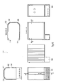
- the U-shaped base consists of a base plate 401 and two mesh walls 402, 403, with one rear mesh wall 403 at the rear end of the base plate 401 and the other front mesh wall 402 spaced from the front end of the base plate 401.
- the counter guide means 404,405 are centrally formed, which engage in the insertion of the heat exchanger 200 in the base 400 in the guide means 109 of the plastic molded parts 100.
- lattice wall ledges 406, 407, 408, 40 spaced from each edge of the lattice walls 402, 403 are integrally formed; that is, on each grid wall 402; 403 two grid wall strips 406, 407; 408, 409, which extend upwards from the base plate 401 and are formed at the end in the form of latching pieces 410, 41, 412, 433.
- the base plate 401 has between the mesh walls 402,403 and at the edges of the base plate 401 upstanding first lugs 414,415 in front of the front grid wall 402 and upwardly projecting second lugs 416.417 in front of the rear grid wall 403.
- the front grid wall 402 is spaced from the front end of the base plate 401. Between the front grid wall 402 and the front end of the base plate 401 are elongated formations 420,421 on the base plate 401 and spaced apart on the outer surface of the front grid wall 402 of the base plate 401 and the front end facing third lugs 422,423 for receiving a Lustererklemme on a front portion the base plate 401 is arranged.
- the lid 500 has a hood 501 with a U-shaped cross section, which surrounds the grid walls 402, 403 of the base 400. Both at the one front end of the hood 501 and at the other rear end of the hood 501 are formed with a distance which corresponds approximately to a wall thickness of the mesh walls 402,403, circumferential ridges forming the end cap edges 501,502 and at which edges of the mesh walls 402,403 after the Insert the lid 500 on the base 400 abut.
- the hood 501 Corresponding to the locking pieces 406,407,408,409 on the two lattice walls 402,403 are on the hood 501 on the hood edges 501,502 aufsitzend fourth lugs 506,507,508,509 as further fixing and corresponding to the rectangular openings 418,419 each at the rear edge and each at the bottom of the hood 501, a first locking element 518 and a second locking element 519 integrally formed.
- the hood 501 In the region between the circumferential elevations or cover edges 501, 502, the hood 501 is lined with a sheet or foil of heat-reflecting material.
- the lid 500 includes a box-shaped cover portion 520 which, when the case 200 is closed, covers the luster terminals mounted on the front portion of the base plate 401 of the pedestal 400.
Landscapes
- Engineering & Computer Science (AREA)
- Physics & Mathematics (AREA)
- Thermal Sciences (AREA)
- Chemical & Material Sciences (AREA)
- Combustion & Propulsion (AREA)
- Mechanical Engineering (AREA)
- General Engineering & Computer Science (AREA)
- Domestic Hot-Water Supply Systems And Details Of Heating Systems (AREA)
- Heat-Exchange Devices With Radiators And Conduit Assemblies (AREA)
- Yarns And Mechanical Finishing Of Yarns Or Ropes (AREA)
- Resistance Heating (AREA)
- Air-Conditioning For Vehicles (AREA)
- External Artificial Organs (AREA)
- Lining Or Joining Of Plastics Or The Like (AREA)
- Control And Other Processes For Unpacking Of Materials (AREA)
- Heat-Pump Type And Storage Water Heaters (AREA)
Priority Applications (1)
| Application Number | Priority Date | Filing Date | Title |
|---|---|---|---|
| PL07106363T PL1847785T3 (pl) | 2006-04-19 | 2007-04-18 | Nagrzewnica |
Applications Claiming Priority (1)
| Application Number | Priority Date | Filing Date | Title |
|---|---|---|---|
| DE102006018151A DE102006018151B4 (de) | 2006-04-19 | 2006-04-19 | Heizgerät |
Publications (2)
| Publication Number | Publication Date |
|---|---|
| EP1847785A1 true EP1847785A1 (fr) | 2007-10-24 |
| EP1847785B1 EP1847785B1 (fr) | 2011-10-19 |
Family
ID=38292645
Family Applications (1)
| Application Number | Title | Priority Date | Filing Date |
|---|---|---|---|
| EP07106363A Active EP1847785B1 (fr) | 2006-04-19 | 2007-04-18 | Appareil de chauffage |
Country Status (6)
| Country | Link |
|---|---|
| EP (1) | EP1847785B1 (fr) |
| AT (1) | ATE529708T1 (fr) |
| DE (1) | DE102006018151B4 (fr) |
| DK (1) | DK1847785T3 (fr) |
| ES (1) | ES2371669T3 (fr) |
| PL (1) | PL1847785T3 (fr) |
Cited By (4)
| Publication number | Priority date | Publication date | Assignee | Title |
|---|---|---|---|---|
| WO2013060647A1 (fr) * | 2011-10-24 | 2013-05-02 | Stego-Holding Gmbh | Corps de refroidissement et de retenue pour éléments chauffants, appareil de chauffage et procédé de fabrication d'un corps de refroidissement et de retenue |
| DE102013001441A1 (de) * | 2013-01-29 | 2014-07-31 | Esw Gmbh | Heizungsanordnung zum Aufheizen eines die Heizungsanordnung durchströmenden Mediums |
| US9661688B2 (en) | 2011-10-24 | 2017-05-23 | Stego-Holding Gmbh | Cooling and retaining body for heating elements, heating appliance and method for producing a cooling and retaining body |
| RU2845889C2 (ru) * | 2021-05-05 | 2025-08-26 | Штего Холдинг Гмбх | Держатель, нагреватель и способ |
Families Citing this family (7)
| Publication number | Priority date | Publication date | Assignee | Title |
|---|---|---|---|---|
| DE102017011637A1 (de) * | 2017-12-15 | 2019-06-19 | Stiebel Eltron Gmbh & Co. Kg | Elektrisches Heizgerät mit einem Labyrinth |
| DE102018131766B3 (de) * | 2018-12-11 | 2020-03-26 | Stego-Holding Gmbh | Haltekörper, Heizgerät und Verfahren |
| DE102021106299A1 (de) | 2021-03-16 | 2022-09-22 | Eberspächer Catem Gmbh & Co. Kg | Elektrische Heizvorrichtung |
| DE102021111665B4 (de) | 2021-05-05 | 2022-12-01 | Stego-Holding Gmbh | Haltevorrichtung, Heizgerät und Verfahren |
| USD1030014S1 (en) | 2021-05-05 | 2024-06-04 | Stego-Holding Gmbh | Convector heater |
| USD1038348S1 (en) | 2021-05-05 | 2024-08-06 | Stego-Holding Gmbh | Convector heater |
| USD1030013S1 (en) | 2021-08-17 | 2024-06-04 | Stego-Holding Gmbh | Convector heater |
Citations (10)
| Publication number | Priority date | Publication date | Assignee | Title |
|---|---|---|---|---|
| FR56471E (fr) * | 1946-08-10 | 1952-09-25 | Appareil de chauffage à canaux multiples | |
| FR2292396A1 (fr) * | 1974-11-19 | 1976-06-18 | Toure Maurice | Dispositif chauffant |
| DE3119302A1 (de) * | 1980-05-14 | 1982-02-18 | Matsushita Electric Industrial Co., Ltd., Kadoma, Osaka | Luftheizvorrichtung |
| EP0937595A2 (fr) * | 1998-02-20 | 1999-08-25 | Micro Compact Car AG | Installation de chauffage ou de climatisation pour véhicules |
| FR2805336A1 (fr) * | 2000-02-23 | 2001-08-24 | Atlantic Industrie Sas | Dispositif de support de corps de chauffe |
| WO2003005770A2 (fr) * | 2001-07-02 | 2003-01-16 | Soy Erdinc | Chauffage par panneau convecteur electrique |
| US20030015520A1 (en) * | 2001-07-18 | 2003-01-23 | Guomo Jiang | PTC heater |
| EP1432287A1 (fr) * | 2002-12-19 | 2004-06-23 | Catem GmbH & Co.KG | Dispositif de chauffage électrique avec boítier |
| EP1574803A2 (fr) * | 2004-02-27 | 2005-09-14 | Marin Camara, Miguel | Radiateur électrique modulaire |
| DE202005020765U1 (de) * | 2005-08-10 | 2006-07-06 | Stego-Holding Gmbh | Vorrichtung zum Übertragen von Wärme von einem Heizelement auf Umgebungsluft |
Family Cites Families (4)
| Publication number | Priority date | Publication date | Assignee | Title |
|---|---|---|---|---|
| DE1950766U (de) * | 1966-09-14 | 1966-12-01 | Petz Elektro Waerme Techn | Heizluefter mit axialgeblaese. |
| DE19604218C2 (de) * | 1996-02-06 | 1998-03-26 | Loh Kg Rittal Werk | Heizgerät mit einem PTC-Element und einem Profilkontaktkörper |
| DE10148623B4 (de) * | 2001-10-02 | 2004-05-13 | Siemens Ag | Vorrichtung und Anordnung zur Befestigung eines Profilteils an einer Tragschiene |
| DE10226557C1 (de) * | 2002-06-14 | 2003-08-14 | Stiebel Eltron Gmbh & Co Kg | Kanalkörper, insbesondere für einen Durchlauferhitzer |
-
2006
- 2006-04-19 DE DE102006018151A patent/DE102006018151B4/de not_active Expired - Lifetime
-
2007
- 2007-04-18 ES ES07106363T patent/ES2371669T3/es active Active
- 2007-04-18 EP EP07106363A patent/EP1847785B1/fr active Active
- 2007-04-18 PL PL07106363T patent/PL1847785T3/pl unknown
- 2007-04-18 AT AT07106363T patent/ATE529708T1/de active
- 2007-04-18 DK DK07106363.0T patent/DK1847785T3/da active
Patent Citations (10)
| Publication number | Priority date | Publication date | Assignee | Title |
|---|---|---|---|---|
| FR56471E (fr) * | 1946-08-10 | 1952-09-25 | Appareil de chauffage à canaux multiples | |
| FR2292396A1 (fr) * | 1974-11-19 | 1976-06-18 | Toure Maurice | Dispositif chauffant |
| DE3119302A1 (de) * | 1980-05-14 | 1982-02-18 | Matsushita Electric Industrial Co., Ltd., Kadoma, Osaka | Luftheizvorrichtung |
| EP0937595A2 (fr) * | 1998-02-20 | 1999-08-25 | Micro Compact Car AG | Installation de chauffage ou de climatisation pour véhicules |
| FR2805336A1 (fr) * | 2000-02-23 | 2001-08-24 | Atlantic Industrie Sas | Dispositif de support de corps de chauffe |
| WO2003005770A2 (fr) * | 2001-07-02 | 2003-01-16 | Soy Erdinc | Chauffage par panneau convecteur electrique |
| US20030015520A1 (en) * | 2001-07-18 | 2003-01-23 | Guomo Jiang | PTC heater |
| EP1432287A1 (fr) * | 2002-12-19 | 2004-06-23 | Catem GmbH & Co.KG | Dispositif de chauffage électrique avec boítier |
| EP1574803A2 (fr) * | 2004-02-27 | 2005-09-14 | Marin Camara, Miguel | Radiateur électrique modulaire |
| DE202005020765U1 (de) * | 2005-08-10 | 2006-07-06 | Stego-Holding Gmbh | Vorrichtung zum Übertragen von Wärme von einem Heizelement auf Umgebungsluft |
Cited By (10)
| Publication number | Priority date | Publication date | Assignee | Title |
|---|---|---|---|---|
| WO2013060647A1 (fr) * | 2011-10-24 | 2013-05-02 | Stego-Holding Gmbh | Corps de refroidissement et de retenue pour éléments chauffants, appareil de chauffage et procédé de fabrication d'un corps de refroidissement et de retenue |
| CN103891399A (zh) * | 2011-10-24 | 2014-06-25 | 斯特格控股有限公司 | 用于加热元件的冷却与保持装置、加热器以及生产冷却与保持装置的方法 |
| JP2014534573A (ja) * | 2011-10-24 | 2014-12-18 | シュテゴ−ホールディング ゲゼルシャフト ミット ベシュレンクテル ハフツングSTEGO−HOLDING GmbH | 加熱素子用の冷却・保持体、ヒータ、および冷却・保持体の製造方法 |
| CN103891399B (zh) * | 2011-10-24 | 2016-01-20 | 斯特格控股有限公司 | 用于加热元件的冷却与保持装置、加热器以及生产冷却与保持装置的方法 |
| RU2599530C2 (ru) * | 2011-10-24 | 2016-10-10 | Штего-Холдинг Гмбх | Охлаждающий и удерживающий корпус для нагревательных элементов, нагревательное устройство и способ изготовления охлаждающего и удерживающего корпуса |
| US9661688B2 (en) | 2011-10-24 | 2017-05-23 | Stego-Holding Gmbh | Cooling and retaining body for heating elements, heating appliance and method for producing a cooling and retaining body |
| US9661689B2 (en) | 2011-10-24 | 2017-05-23 | Stego-Holding Gmbh | Cooling and holding device for heating-elements, heater and method for producing a cooling and holding device |
| DE102013001441A1 (de) * | 2013-01-29 | 2014-07-31 | Esw Gmbh | Heizungsanordnung zum Aufheizen eines die Heizungsanordnung durchströmenden Mediums |
| DE102013001441B4 (de) * | 2013-01-29 | 2015-07-16 | Esw Gmbh | Heizungsanordnung zum Aufheizen eines die Heizungsanordnung durchströmenden Mediums |
| RU2845889C2 (ru) * | 2021-05-05 | 2025-08-26 | Штего Холдинг Гмбх | Держатель, нагреватель и способ |
Also Published As
| Publication number | Publication date |
|---|---|
| DE102006018151B4 (de) | 2012-07-19 |
| PL1847785T3 (pl) | 2012-03-30 |
| ATE529708T1 (de) | 2011-11-15 |
| ES2371669T3 (es) | 2012-01-09 |
| DK1847785T3 (da) | 2012-02-13 |
| DE102006018151A1 (de) | 2007-10-25 |
| EP1847785B1 (fr) | 2011-10-19 |
Similar Documents
| Publication | Publication Date | Title |
|---|---|---|
| EP1847785B1 (fr) | Appareil de chauffage | |
| EP1847786B1 (fr) | Appareil de chauffage | |
| EP2017548B1 (fr) | Dispositif de chauffage électrique, en particulier pour véhicules automobiles | |
| EP1432287B1 (fr) | Dispositif de chauffage électrique avec boîtier | |
| EP1327834B1 (fr) | Elément de radiation pour appareil de chauffage | |
| EP0927510B1 (fr) | Boitier dissipateur de chaleur servant a loger des composants electriques ou electroniques | |
| EP1921896B1 (fr) | Elément produisant de la chaleur pour dispositif chauffant électrique et son procédé de fabrication | |
| DE10037161C2 (de) | Temperaturschalter | |
| EP1515587B1 (fr) | Dispositif de chauffage électrique muni d'un élément chauffant scellé | |
| EP2564448B1 (fr) | Batterie comprenant une plaque de refroidissement et véhicule à moteur comprenant une batterie correspondante | |
| EP2298582B1 (fr) | Dispositif de chauffage électrique et son procédé de fabrication | |
| EP2637474A1 (fr) | Elément chauffant | |
| EP3843221B1 (fr) | Cadre de support pour un connecteur | |
| DE112016000688B4 (de) | Elektrische Heizvorrichtung | |
| DE102010015457A1 (de) | Federkraftklemmanschluss und Klemmbauelement | |
| EP2884199B1 (fr) | Dispositif de chauffage électrique | |
| EP1523226B1 (fr) | Ensemble de chauffage comprenant des éléments PTC, particulièrement pour véhicules à moteurs | |
| EP0860846B1 (fr) | Régulateur électrique de puissance, en particulier pour appareil à chauffage électrique | |
| DE202005020765U1 (de) | Vorrichtung zum Übertragen von Wärme von einem Heizelement auf Umgebungsluft | |
| AT402768B (de) | Schraubenlose elektrische anschluss- oder verbindungsklemme | |
| DE19830512A1 (de) | Kühlkörper mit Querrippen | |
| DE202022106450U1 (de) | Wärmestrahler | |
| DE102007055868A1 (de) | Endkappe zur Anordnung an einem offenen Ende eines Hohlprofils | |
| EP1253032A2 (fr) | Dispositif de chauffage électrique avec un bloc chauffant monté dans un cadre | |
| DE102019110622A1 (de) | Elektrischer Heizkörper |
Legal Events
| Date | Code | Title | Description |
|---|---|---|---|
| PUAI | Public reference made under article 153(3) epc to a published international application that has entered the european phase |
Free format text: ORIGINAL CODE: 0009012 |
|
| AK | Designated contracting states |
Kind code of ref document: A1 Designated state(s): AT BE BG CH CY CZ DE DK EE ES FI FR GB GR HU IE IS IT LI LT LU LV MC MT NL PL PT RO SE SI SK TR |
|
| AX | Request for extension of the european patent |
Extension state: AL BA HR MK YU |
|
| 17P | Request for examination filed |
Effective date: 20071022 |
|
| AKX | Designation fees paid |
Designated state(s): AT BE BG CH CY CZ DE DK EE ES FI FR GB GR HU IE IS IT LI LT LU LV MC MT NL PL PT RO SE SI SK TR |
|
| 17Q | First examination report despatched |
Effective date: 20110311 |
|
| GRAP | Despatch of communication of intention to grant a patent |
Free format text: ORIGINAL CODE: EPIDOSNIGR1 |
|
| GRAS | Grant fee paid |
Free format text: ORIGINAL CODE: EPIDOSNIGR3 |
|
| GRAA | (expected) grant |
Free format text: ORIGINAL CODE: 0009210 |
|
| AK | Designated contracting states |
Kind code of ref document: B1 Designated state(s): AT BE BG CH CY CZ DE DK EE ES FI FR GB GR HU IE IS IT LI LT LU LV MC MT NL PL PT RO SE SI SK TR |
|
| REG | Reference to a national code |
Ref country code: GB Ref legal event code: FG4D Free format text: NOT ENGLISH |
|
| REG | Reference to a national code |
Ref country code: CH Ref legal event code: EP |
|
| REG | Reference to a national code |
Ref country code: IE Ref legal event code: FG4D |
|
| REG | Reference to a national code |
Ref country code: NL Ref legal event code: T3 |
|
| REG | Reference to a national code |
Ref country code: ES Ref legal event code: FG2A Ref document number: 2371669 Country of ref document: ES Kind code of ref document: T3 Effective date: 20120109 |
|
| REG | Reference to a national code |
Ref country code: DE Ref legal event code: R096 Ref document number: 502007008423 Country of ref document: DE Effective date: 20120112 |
|
| REG | Reference to a national code |
Ref country code: SE Ref legal event code: TRGR |
|
| REG | Reference to a national code |
Ref country code: DK Ref legal event code: T3 |
|
| LTIE | Lt: invalidation of european patent or patent extension |
Effective date: 20111019 |
|
| REG | Reference to a national code |
Ref country code: PL Ref legal event code: T3 |
|
| PG25 | Lapsed in a contracting state [announced via postgrant information from national office to epo] |
Ref country code: LT Free format text: LAPSE BECAUSE OF FAILURE TO SUBMIT A TRANSLATION OF THE DESCRIPTION OR TO PAY THE FEE WITHIN THE PRESCRIBED TIME-LIMIT Effective date: 20111019 Ref country code: IS Free format text: LAPSE BECAUSE OF FAILURE TO SUBMIT A TRANSLATION OF THE DESCRIPTION OR TO PAY THE FEE WITHIN THE PRESCRIBED TIME-LIMIT Effective date: 20120219 |
|
| REG | Reference to a national code |
Ref country code: IE Ref legal event code: FD4D |
|
| PG25 | Lapsed in a contracting state [announced via postgrant information from national office to epo] |
Ref country code: GR Free format text: LAPSE BECAUSE OF FAILURE TO SUBMIT A TRANSLATION OF THE DESCRIPTION OR TO PAY THE FEE WITHIN THE PRESCRIBED TIME-LIMIT Effective date: 20120120 Ref country code: SI Free format text: LAPSE BECAUSE OF FAILURE TO SUBMIT A TRANSLATION OF THE DESCRIPTION OR TO PAY THE FEE WITHIN THE PRESCRIBED TIME-LIMIT Effective date: 20111019 Ref country code: LV Free format text: LAPSE BECAUSE OF FAILURE TO SUBMIT A TRANSLATION OF THE DESCRIPTION OR TO PAY THE FEE WITHIN THE PRESCRIBED TIME-LIMIT Effective date: 20111019 Ref country code: PT Free format text: LAPSE BECAUSE OF FAILURE TO SUBMIT A TRANSLATION OF THE DESCRIPTION OR TO PAY THE FEE WITHIN THE PRESCRIBED TIME-LIMIT Effective date: 20120220 |
|
| PG25 | Lapsed in a contracting state [announced via postgrant information from national office to epo] |
Ref country code: CY Free format text: LAPSE BECAUSE OF FAILURE TO SUBMIT A TRANSLATION OF THE DESCRIPTION OR TO PAY THE FEE WITHIN THE PRESCRIBED TIME-LIMIT Effective date: 20111019 |
|
| PG25 | Lapsed in a contracting state [announced via postgrant information from national office to epo] |
Ref country code: EE Free format text: LAPSE BECAUSE OF FAILURE TO SUBMIT A TRANSLATION OF THE DESCRIPTION OR TO PAY THE FEE WITHIN THE PRESCRIBED TIME-LIMIT Effective date: 20111019 Ref country code: SK Free format text: LAPSE BECAUSE OF FAILURE TO SUBMIT A TRANSLATION OF THE DESCRIPTION OR TO PAY THE FEE WITHIN THE PRESCRIBED TIME-LIMIT Effective date: 20111019 Ref country code: IE Free format text: LAPSE BECAUSE OF FAILURE TO SUBMIT A TRANSLATION OF THE DESCRIPTION OR TO PAY THE FEE WITHIN THE PRESCRIBED TIME-LIMIT Effective date: 20111019 Ref country code: BG Free format text: LAPSE BECAUSE OF FAILURE TO SUBMIT A TRANSLATION OF THE DESCRIPTION OR TO PAY THE FEE WITHIN THE PRESCRIBED TIME-LIMIT Effective date: 20120119 |
|
| PLBE | No opposition filed within time limit |
Free format text: ORIGINAL CODE: 0009261 |
|
| STAA | Information on the status of an ep patent application or granted ep patent |
Free format text: STATUS: NO OPPOSITION FILED WITHIN TIME LIMIT |
|
| PG25 | Lapsed in a contracting state [announced via postgrant information from national office to epo] |
Ref country code: RO Free format text: LAPSE BECAUSE OF FAILURE TO SUBMIT A TRANSLATION OF THE DESCRIPTION OR TO PAY THE FEE WITHIN THE PRESCRIBED TIME-LIMIT Effective date: 20111019 |
|
| 26N | No opposition filed |
Effective date: 20120720 |
|
| BERE | Be: lapsed |
Owner name: STEGO-HOLDING G.M.B.H. Effective date: 20120430 |
|
| REG | Reference to a national code |
Ref country code: DE Ref legal event code: R097 Ref document number: 502007008423 Country of ref document: DE Effective date: 20120720 |
|
| PG25 | Lapsed in a contracting state [announced via postgrant information from national office to epo] |
Ref country code: MC Free format text: LAPSE BECAUSE OF NON-PAYMENT OF DUE FEES Effective date: 20120430 |
|
| REG | Reference to a national code |
Ref country code: CH Ref legal event code: PL |
|
| PG25 | Lapsed in a contracting state [announced via postgrant information from national office to epo] |
Ref country code: BE Free format text: LAPSE BECAUSE OF NON-PAYMENT OF DUE FEES Effective date: 20120430 Ref country code: LI Free format text: LAPSE BECAUSE OF NON-PAYMENT OF DUE FEES Effective date: 20120430 Ref country code: CH Free format text: LAPSE BECAUSE OF NON-PAYMENT OF DUE FEES Effective date: 20120430 |
|
| REG | Reference to a national code |
Ref country code: AT Ref legal event code: MM01 Ref document number: 529708 Country of ref document: AT Kind code of ref document: T Effective date: 20120418 |
|
| PG25 | Lapsed in a contracting state [announced via postgrant information from national office to epo] |
Ref country code: FI Free format text: LAPSE BECAUSE OF FAILURE TO SUBMIT A TRANSLATION OF THE DESCRIPTION OR TO PAY THE FEE WITHIN THE PRESCRIBED TIME-LIMIT Effective date: 20111019 |
|
| PG25 | Lapsed in a contracting state [announced via postgrant information from national office to epo] |
Ref country code: AT Free format text: LAPSE BECAUSE OF NON-PAYMENT OF DUE FEES Effective date: 20120418 Ref country code: MT Free format text: LAPSE BECAUSE OF FAILURE TO SUBMIT A TRANSLATION OF THE DESCRIPTION OR TO PAY THE FEE WITHIN THE PRESCRIBED TIME-LIMIT Effective date: 20111019 |
|
| PG25 | Lapsed in a contracting state [announced via postgrant information from national office to epo] |
Ref country code: TR Free format text: LAPSE BECAUSE OF FAILURE TO SUBMIT A TRANSLATION OF THE DESCRIPTION OR TO PAY THE FEE WITHIN THE PRESCRIBED TIME-LIMIT Effective date: 20111019 |
|
| PG25 | Lapsed in a contracting state [announced via postgrant information from national office to epo] |
Ref country code: LU Free format text: LAPSE BECAUSE OF NON-PAYMENT OF DUE FEES Effective date: 20120418 |
|
| PG25 | Lapsed in a contracting state [announced via postgrant information from national office to epo] |
Ref country code: HU Free format text: LAPSE BECAUSE OF FAILURE TO SUBMIT A TRANSLATION OF THE DESCRIPTION OR TO PAY THE FEE WITHIN THE PRESCRIBED TIME-LIMIT Effective date: 20070418 |
|
| REG | Reference to a national code |
Ref country code: FR Ref legal event code: PLFP Year of fee payment: 10 |
|
| REG | Reference to a national code |
Ref country code: FR Ref legal event code: PLFP Year of fee payment: 11 |
|
| REG | Reference to a national code |
Ref country code: FR Ref legal event code: PLFP Year of fee payment: 12 |
|
| P01 | Opt-out of the competence of the unified patent court (upc) registered |
Effective date: 20230602 |
|
| PGFP | Annual fee paid to national office [announced via postgrant information from national office to epo] |
Ref country code: SE Payment date: 20250228 Year of fee payment: 19 |
|
| PGFP | Annual fee paid to national office [announced via postgrant information from national office to epo] |
Ref country code: NL Payment date: 20250424 Year of fee payment: 19 |
|
| PGFP | Annual fee paid to national office [announced via postgrant information from national office to epo] |
Ref country code: DE Payment date: 20250430 Year of fee payment: 19 |
|
| PGFP | Annual fee paid to national office [announced via postgrant information from national office to epo] |
Ref country code: ES Payment date: 20250513 Year of fee payment: 19 Ref country code: DK Payment date: 20250424 Year of fee payment: 19 |
|
| PGFP | Annual fee paid to national office [announced via postgrant information from national office to epo] |
Ref country code: IT Payment date: 20250422 Year of fee payment: 19 |
|
| PGFP | Annual fee paid to national office [announced via postgrant information from national office to epo] |
Ref country code: FR Payment date: 20250424 Year of fee payment: 19 |
|
| PGFP | Annual fee paid to national office [announced via postgrant information from national office to epo] |
Ref country code: CZ Payment date: 20250404 Year of fee payment: 19 |
|
| PGFP | Annual fee paid to national office [announced via postgrant information from national office to epo] |
Ref country code: GB Payment date: 20260304 Year of fee payment: 20 |
|
| PGFP | Annual fee paid to national office [announced via postgrant information from national office to epo] |
Ref country code: PL Payment date: 20260324 Year of fee payment: 20 |