EP2017548B1 - Dispositif de chauffage électrique, en particulier pour véhicules automobiles - Google Patents
Dispositif de chauffage électrique, en particulier pour véhicules automobiles Download PDFInfo
- Publication number
- EP2017548B1 EP2017548B1 EP07014323A EP07014323A EP2017548B1 EP 2017548 B1 EP2017548 B1 EP 2017548B1 EP 07014323 A EP07014323 A EP 07014323A EP 07014323 A EP07014323 A EP 07014323A EP 2017548 B1 EP2017548 B1 EP 2017548B1
- Authority
- EP
- European Patent Office
- Prior art keywords
- elements
- contact
- control unit
- heating device
- electric heating
- Prior art date
- Legal status (The legal status is an assumption and is not a legal conclusion. Google has not performed a legal analysis and makes no representation as to the accuracy of the status listed.)
- Not-in-force
Links
Images

Classifications
-
- F—MECHANICAL ENGINEERING; LIGHTING; HEATING; WEAPONS; BLASTING
- F24—HEATING; RANGES; VENTILATING
- F24H—FLUID HEATERS, e.g. WATER OR AIR HEATERS, HAVING HEAT-GENERATING MEANS, e.g. HEAT PUMPS, IN GENERAL
- F24H9/00—Details
- F24H9/18—Arrangement or mounting of grates or heating means
- F24H9/1854—Arrangement or mounting of grates or heating means for air heaters
- F24H9/1863—Arrangement or mounting of electric heating means
-
- B—PERFORMING OPERATIONS; TRANSPORTING
- B60—VEHICLES IN GENERAL
- B60H—ARRANGEMENTS OF HEATING, COOLING, VENTILATING OR OTHER AIR-TREATING DEVICES SPECIALLY ADAPTED FOR PASSENGER OR GOODS SPACES OF VEHICLES
- B60H1/00—Heating, cooling or ventilating devices
- B60H1/02—Heating, cooling or ventilating devices the heat being derived from the propulsion plant
- B60H1/14—Heating, cooling or ventilating devices the heat being derived from the propulsion plant other than from cooling liquid of the plant
- B60H1/18—Heating, cooling or ventilating devices the heat being derived from the propulsion plant other than from cooling liquid of the plant the air being heated from the plant exhaust gases
- B60H1/20—Heating, cooling or ventilating devices the heat being derived from the propulsion plant other than from cooling liquid of the plant the air being heated from the plant exhaust gases using an intermediate heat-transferring medium
-
- B—PERFORMING OPERATIONS; TRANSPORTING
- B60—VEHICLES IN GENERAL
- B60H—ARRANGEMENTS OF HEATING, COOLING, VENTILATING OR OTHER AIR-TREATING DEVICES SPECIALLY ADAPTED FOR PASSENGER OR GOODS SPACES OF VEHICLES
- B60H1/00—Heating, cooling or ventilating devices
-
- B—PERFORMING OPERATIONS; TRANSPORTING
- B60—VEHICLES IN GENERAL
- B60H—ARRANGEMENTS OF HEATING, COOLING, VENTILATING OR OTHER AIR-TREATING DEVICES SPECIALLY ADAPTED FOR PASSENGER OR GOODS SPACES OF VEHICLES
- B60H1/00—Heating, cooling or ventilating devices
- B60H1/22—Heating, cooling or ventilating devices the heat source being other than the propulsion plant
-
- F—MECHANICAL ENGINEERING; LIGHTING; HEATING; WEAPONS; BLASTING
- F24—HEATING; RANGES; VENTILATING
- F24H—FLUID HEATERS, e.g. WATER OR AIR HEATERS, HAVING HEAT-GENERATING MEANS, e.g. HEAT PUMPS, IN GENERAL
- F24H3/00—Air heaters
- F24H3/02—Air heaters with forced circulation
- F24H3/04—Air heaters with forced circulation the air being in direct contact with the heating medium, e.g. electric heating element
- F24H3/0405—Air heaters with forced circulation the air being in direct contact with the heating medium, e.g. electric heating element using electric energy supply, e.g. the heating medium being a resistive element; Heating by direct contact, i.e. with resistive elements, electrodes and fins being bonded together without additional element in-between
- F24H3/0429—For vehicles
- F24H3/0435—Structures comprising heat spreading elements in the form of fins
-
- F—MECHANICAL ENGINEERING; LIGHTING; HEATING; WEAPONS; BLASTING
- F24—HEATING; RANGES; VENTILATING
- F24H—FLUID HEATERS, e.g. WATER OR AIR HEATERS, HAVING HEAT-GENERATING MEANS, e.g. HEAT PUMPS, IN GENERAL
- F24H3/00—Air heaters
- F24H3/02—Air heaters with forced circulation
- F24H3/04—Air heaters with forced circulation the air being in direct contact with the heating medium, e.g. electric heating element
- F24H3/0405—Air heaters with forced circulation the air being in direct contact with the heating medium, e.g. electric heating element using electric energy supply, e.g. the heating medium being a resistive element; Heating by direct contact, i.e. with resistive elements, electrodes and fins being bonded together without additional element in-between
- F24H3/0429—For vehicles
- F24H3/0441—Interfaces between the electrodes of a resistive heating element and the power supply means
- F24H3/0447—Forms of the electrode terminals, e.g. tongues or clips
-
- F—MECHANICAL ENGINEERING; LIGHTING; HEATING; WEAPONS; BLASTING
- F24—HEATING; RANGES; VENTILATING
- F24H—FLUID HEATERS, e.g. WATER OR AIR HEATERS, HAVING HEAT-GENERATING MEANS, e.g. HEAT PUMPS, IN GENERAL
- F24H3/00—Air heaters
- F24H3/02—Air heaters with forced circulation
- F24H3/04—Air heaters with forced circulation the air being in direct contact with the heating medium, e.g. electric heating element
- F24H3/0405—Air heaters with forced circulation the air being in direct contact with the heating medium, e.g. electric heating element using electric energy supply, e.g. the heating medium being a resistive element; Heating by direct contact, i.e. with resistive elements, electrodes and fins being bonded together without additional element in-between
- F24H3/0429—For vehicles
- F24H3/0452—Frame constructions
- F24H3/0464—Two-piece frames, e.g. two-shell frames, also including frames as a central body with two covers
-
- F—MECHANICAL ENGINEERING; LIGHTING; HEATING; WEAPONS; BLASTING
- F24—HEATING; RANGES; VENTILATING
- F24H—FLUID HEATERS, e.g. WATER OR AIR HEATERS, HAVING HEAT-GENERATING MEANS, e.g. HEAT PUMPS, IN GENERAL
- F24H9/00—Details
- F24H9/18—Arrangement or mounting of grates or heating means
- F24H9/1854—Arrangement or mounting of grates or heating means for air heaters
- F24H9/1863—Arrangement or mounting of electric heating means
- F24H9/1872—PTC resistor
-
- H—ELECTRICITY
- H05—ELECTRIC TECHNIQUES NOT OTHERWISE PROVIDED FOR
- H05K—PRINTED CIRCUITS; CASINGS OR CONSTRUCTIONAL DETAILS OF ELECTRIC APPARATUS; MANUFACTURE OF ASSEMBLAGES OF ELECTRICAL COMPONENTS
- H05K1/00—Printed circuits
- H05K1/02—Details
- H05K1/0201—Thermal arrangements, e.g. for cooling, heating or preventing overheating
- H05K1/0203—Cooling of mounted components
Definitions
- the invention relates to an electric heater for air heating, which is particularly suitable for use as electric auxiliary heating in motor vehicles.
- electric heaters are used for heating the interior and / or the engine.
- An additional electric heater is required in particular after starting the engine, as long as the engine does not provide sufficient heat energy available.
- Consumption-optimized combustion engines even require in principle the use of additional electrical heating.
- heaters are not limited to the automotive field, they are also suitable for a variety of other applications, such as in the field of domestic (air conditioning), industrial equipment and the like.
- the heating device described comprises a plurality of heating elements assembled into a heating block.
- the heating block is held together with a control device for controlling the heating elements in a common frame.
- the control device thus forms a structural unit with the heating block held in the frame.
- the control device comprises power electronics with electronic switches, which are each provided with a heat sink.
- the control device is arranged so that a part of the air flow to be heated flows against the control device, in particular the cooling elements, for cooling the electronic switches.
- EP-A-1 338 451 discloses an electric heater according to the preamble of claim 1.
- the electronic switches in particular in the form of power transistors controlling the current supplied to the heating elements, are mounted with one side directly on a printed circuit board.
- a cooling element is provided on the opposite side of the circuit board. Such a cooling element, which directly contacts the power transistor, can dissipate the heat loss of the power transistor in a simple manner and in sufficient quantity.
- a cooling element As a cooling element comes in the aforementioned prior art, a U-shaped heat sink designed for use with cooling fins or fingers that protrude from a base. At the bottom of the heat sink, a pin is provided which can be inserted into the circuit board for contacting the power transistor.
- a cooling element according to the present invention may be any component which is suitable to dissipate heat by conduction of heat from the power transistors and effectively deliver by heat transfer to the air flowing around.
- the cooling element is exposed to the air which is to be heated by the electric heater, i. flows in a guided to the electric heater channel.
- moisture collects in the channel, which either enters directly into the incoming air or condenses out of the inflowing air.
- Object of the present invention is therefore to develop an electrical heating device of the type mentioned in such a way that this easy to manufacture and the control device of the electric heater can be reliably protected from penetrating moisture.
- the present invention provides an electric heating device with the features of claim 1. This differs from the generic state of the art in that the control device is held on a control device carrier and that sealing elements are provided between the control device carrier and the heating block receiving Schublockgephaseuse, which protrudes from the contact or cooling elements and by clamping between the control device carrier and the heating block housing are sealed.
- the structural unit is produced in that the control device carrier is connected to the heating block housing.
- the contact elements which provide for a supply of the heating block with electric current, as well as the, the cooling of the electronic switch causing cooling elements extending between the control device carrier and the Schublockgephaseuse.
- the contact or cooling elements each protrude through at least one sealing element.
- the tightness of the sealing element is caused by the fact that the sealing element between the control device carrier and the Schublockgephaseuse is clamped. This makes it possible to first stress-free to install the sealing elements and only when creating the structural unit of the control device and heating block, ie when connecting the control device carrier with the Schublockgepatuse to clamp the respective sealing elements for sealing contact.
- the electric heater according to the invention can thereby be produced in a simple manner without having to forego a reliable sealing of the control device.
- the electric heater according to the invention can be produced when the or the cooling elements are designed as a pin or leaf-shaped solid body, which are passed for connection to the electronic switch (eg power transistor) through the circuit board and at the electronic switch facing away underside of the PCB protrude this.
- the sealing element sealing or contact surfaces for the sealing elements may be provided both on the cooling elements and the / the contact elements, which deviate from a cylindrical and thus the simple form.
- Such embodiments are to be preferred in particular with regard to a radial clamping of the sealing elements against the inner peripheral surface of the contact or cooling elements.
- the control device carrier and / or the heating block housing may have conical receivers for the sealing elements which surround the passage openings for the contact or cooling elements.
- the sealing elements between the Kirblockgephaseuse and the control device carrier are preferably axially, i. set in the longitudinal direction of the cooling or contact elements.
- sealing elements are compressed in the longitudinal direction of these elements, resulting in a sealing contact in the radial direction.
- a plurality of electronic switches may be provided.
- usually more than two contact elements for supplying the individual heating elements are provided, which expediently project beyond the heating block housing at that end face on which the control device carrier is located.
- This integral sealing unit can during assembly, for example, thereby be prefixed that the sealing unit is pushed onto the heating block housing superior contact elements. In this way, the sealing elements for the cooling elements are brought to the Schublockgephase in a predetermined position corresponding to the position of the cooling elements when the control device carrier is connected to the Schublockgephase.
- the sealing unit can be manufactured as an injection molded part from a heat-resistant thermoplastic elastomer.
- Such an injection-molded part can for example also be inserted as an insert into an injection mold, which serves for the production of the control device carrier or the heating block housing or a housing half thereof. In this way, the joining steps for the production of the heating device can be reduced.
- the sealing unit is designed as an insert, which is mounted separately, it is preferable to connect the sealing elements together by a base portion.
- this base portion sealingly at the edge of the passage openings between the Kirblockgeophuse and the control device carrier.
- it is furthermore preferable to provide a projecting collar which surrounds the receptacles for the sealing elements on the housing side.
- this projecting collar on the control device carrier, which should have the conical receptacles for the sealing elements for the same reason.
- the sealing element for each of the contact or cooling elements with a plurality of sealing contact surfaces arranged longitudinally relative to these contact or cooling elements. These are preferably arranged conically stepped to each other and preferably predetermined by successively arranged sealing beads.
- the sealing beads are spaced apart in the longitudinal direction of the contact or cooling elements, preferably wherein the respective sealing beads interconnecting material of the sealing elements forms a kind of film hinge that a certain mobility of the individual sealing beads to each other in the longitudinal direction of the contact or Cooling elements allows.
- the sealing elements or the sealing unit during assembly of the electric heater is proposed according to a further preferred embodiment of the present invention to provide a formed on the Studblockgefituse window openings crosspiece on the Schublockgephaseuse, which forms a contact surface for the base portion of the sealing element and thereby initially improves the seal.
- the transverse web expediently forms a substantially planar contact surface for the base section.
- the crosspiece further has centering receivers in which centering projections formed on the base portion are received. These centering projections are preferably located on the underside of the base section facing away from the sealing elements.
- the centering recesses preferably surround the passage openings for the or the cooling and / or the contact element (s).
- the structural unit between the control device and the heating block is preferably produced by connecting the heating block housing to a control device housing, which comprises the control device carrier.
- the controller housing has a housing cover which includes at least one interface for the supply and control of the heater.
- the controller housing further surrounds a circuit board having cooling elements and electronic switches substantially perpendicular therefrom.
- the control device housing should bring about a certain mechanical protection of the control device. It is not mandatory that this controller housing seal the controller liquid-tight.
- the control device housing serves, in particular, for the electrical connection of the electrical heating device and, if appropriate, the attachment of the control device or the entire heating device.
- the housing cover preferably has a contact rail, which is electrically connected to at least one of the interfaces and the circuit board and placed on the circuit board, which should be understood that the contact rail extends substantially perpendicular to the plane of the circuit board.
- the circuit board also has spring tongues cooperating with the contact elements. These spring tongues are electrically connected to conductor tracks of the printed circuit board, wherein the spring tongues are dimensioned such that the voltage applied to the spring tongues contact elements are securely connected to the circuit board electrically.
- connection is usually effected during insertion of the contact elements in the recessed on the control device carrier passage openings.
- the fixedly mounted on the circuit board cooling elements pass through passages which are recessed on the Schublockgeophuse, preferably the crosspiece. At the end of this insertion movement, the sealing elements between the control device carrier and the Schublockgephaseuse be clamped.
- the structural unit produced in this way is preferably secured by the fact that the control device carrier or the control device housing is latched to the heating block housing.
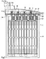
- FIG. 1 an exploded perspective view is shown substantially in the form of a side view of an embodiment of the electric heater according to the invention.
- This has as essential elements a heating block housing 1 and a control device housing 2. Between the two housings 1, 2, a sealing unit 3 is provided.
- the controller housing 2 surrounds a control device 4.
- the Schublockgeophenuse 1 consists of two substantially identical frame halves 10a, 10b, which are in the present case designed as a plastic injection molded part and on the surface of a stiffening grid structure is formed. Between the grid structures of the two frame halves 10a, 10b, a heating block 11, consisting of a plurality of layered or stacked heating elements 12 is arranged. Each of the heating elements 12 consists of one or more resistance heating elements, which in the illustration according to FIG. 1 are concealed behind the longitudinal struts of the stiffening grid, as well as adjacent thereto arranged radiators 13, which are formed in the present case by meandering folded metal sheets. With regard to a good heat transfer and installation of the radiators 13 on the resistance heating elements, which are preferably formed by so-called PTC elements, is located between the PTC elements and the radiators 13 of a heating element 12, a flat sheet metal strip.
- the heating block 11 from the heating elements 12 is held in the frame 10 formed by the two frame halves 10a, 10b.
- the frame 10 elongated longitudinal beams 14a, 14b and at right angles to this extending side rails 15a, 15b.
- FIG. 1 Between the in FIG. 1 upper side rail 15a and the heating block 11 are recessed window openings 16 in the embodiment shown.
- the adjacent window openings 16 separating longitudinal webs 17 surround a free end of the metal strips arranged between the radiators 13 and the resistance heating elements, which continue to form a contact tongue 18 to the outside.
- the contact tongues 18 protrude beyond the in FIG. 1 upper edge of the frame 10.
- the control device housing 2 is essentially formed in two parts with a housing base 21 comprising a control device carrier 20 and a housing cover 22 mounted thereon.
- the housing bottom part 21 is substantially trough-shaped and has fastening flanges 23 on its respective end faces for mounting the electric heating device to a chassis of a motor vehicle.
- the bottom of the Housing lower part 21 forms the control device carrier 20, the inside of the control device housing 2 facing surface is completely flat.
- the control device carrier 20 has a plurality of slotted first passage openings 24a, which are arranged alternately with round passage openings 24b and in the longitudinal direction of the control device carrier 20 one behind the other.
- the first passage openings 24a with a rectangular cross-section are tapered in the longitudinal and transverse direction of the control device carrier 20 in the direction of the control device housing 2.
- the second passage openings 24b with a round cross-sectional area are tapered in the same direction.
- the control device carrier 20 is surrounded by a double groove 27 which is open toward the underside and which is designed such that the front-side edge of the heating block housing 1 fits into the interior of the double grooves 27.
- the housing cover 22 forms a plug-in receptacle 28, are received in the electrical control contacts 29. Further, the housing cover 22 has two electrical supply interfaces 30a, 30b, which are shielded from each other by upstanding walls, the supply plug receptacles 31 a, 31 b form.
- the electrical supply interface 30b is electrically connected to a contact rail 32, which is formed by an electrically conductive sheet, which has a plurality of contacts 33 on its front side facing the control device carrier 20.
- the control contacts 32 are electrically connected to one another behind the contact rail 32 provided further control contact rail, which also forms on its front side contact pin.
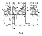
- control device 4 which comprises a printed circuit board 34, on the upper side in the longitudinal direction alternately four double-acting spring tongues 35 and four power transistors 36 are arranged contacted.
- the power transistors 36 are connected to cylindrical cooling elements 37, which are passed through openings recessed in the printed circuit board 34 and project beyond the underside of the printed circuit board 34.
- the cylindrical cooling elements 37 are aligned the second passage openings 24b and the corresponding thereto formed receptacles 26b.
- the sealing unit 3 is formed of a heat-resistant, elastic material, in this case made of EPOM and as a one-piece component, for example by injection molding or casting, formed and comprises a band-shaped base portion 40, pointing to the control device housing 2 top of first and second sealing elements 41 a, 41st b is surmounted. Corresponding thereto, the underside of the base section 40 has centering projections 42.
- Each of the sealing elements 41 consists of two in the longitudinal direction of the cooling elements 37 and the contact tongues 18 successively arranged first and second sealing beads 43a, 43b.
- the first sealing beads 43a have a rectangular base surface with a recess corresponding thereto, the second sealing beads 43b have a correspondingly formed circular basic shape.
- the lower sealing bead 43 'arranged adjacent to the base portion 40 has larger dimensions than the overlying sealing bead 43 ".
- Each of the sealing beads 43 forms circumferential sealing contact surfaces 44 on its outer peripheral surface, which form a conical configuration due to the stepped arrangement of the sealing beads 43a, 43b the lead through the respective sealing element 41 a, 41 b outer sealing surface lead (see. FIG. 3 ).
- the inner circumference of the respective sealing beads 43a, 43b is substantially constant, so that the inner sealing abutment surface 45 formed inside by the beads 43a, 43b has a cylindrical course.
- the heating block housing 1 and the control device housing 2 with the heating and control elements accommodated therein are initially completely prepared for mounting the embodiment shown in the figures.
- heating block housing 1, control device housing 2 and sealing unit 3 for example, the sealing unit 3 is pre-assembled on the heating block side.
- the first sealing elements 41 a so far pushed onto the contact tongues 18 so far that the base portion 40 on a in FIG. 2 illustrated and the window openings 16 on the top covering transverse web 46 rests, which centering 47a, 47b for the centering projections 42 and to the window openings 16 leading passages 48 for the cooling elements 37 spared.
- the preassembled controller housing 2 is connected to the heater block housing 1 to form a structural unit.
- the cooling elements 37 are introduced in alignment into the associated sealing elements 41b and inserted until the upper edge of the heating block housing 1 in the inner double groove 27 is included.
- the respective sealing elements 41 a, 41 b respectively in the associated receptacles 26 a, 26 b are centered due to the conical configurations and finally compressed in the radial direction, since the base portion 40 fixed by engagement with the cross bar 46, the sealing unit 3.
- the free ends of the contact tongues 18 are pushed through the passage openings 24a into the interior of the control device housing 2 and between the double-acting spring tongues 35, whereby an electrical contact between the spring tongues 35 and the contact tongues 18 is produced.
- control contacts 29 are contacted via the control contact rail with the printed circuit board 34, whose corresponding conductor tracks are connected to the power transistors 36.
- the contact pins 33 contact the printed circuit board 34 provided on the contact points, which lead to the power transistors 36 and depending on the switching characteristics of the power transistors 36 can be switched to the spring tongues 35 and thus to the contact blades 18.
- the electrical supply interface 30a for ground is electrically connected to the heater block housing 1 via electrical conductor tracks formed on the control device housing in the region of the double groove 27.
- the cooling elements 37 are located with their front end in the respective window openings sixteenth
- the connection between the Wienblockgeophuse 1 and the controller housing 2 can be secured in various ways, in particular by welding or gluing.
- the embodiment shown in the figures is particularly suitable for cost-effective production of the electric heater, since the lower housing part 21 and the housing cover 22 of the control device housing 2, as well as the two housing halves 10a, 10b can be made by injection molding.
- the sealing unit 3 is connected as separately manufactured from this housing insert during assembly with the housings 1, 2.
- FIG. 2 embodiment shown differs only from the in FIG. 1 Pictured, which are provided in the window openings 16 slotted réelleleitbleche 49, which are clipped to the front end of the cooling elements.
Landscapes
- Engineering & Computer Science (AREA)
- Physics & Mathematics (AREA)
- Thermal Sciences (AREA)
- Mechanical Engineering (AREA)
- Chemical & Material Sciences (AREA)
- Combustion & Propulsion (AREA)
- General Engineering & Computer Science (AREA)
- Microelectronics & Electronic Packaging (AREA)
- Air-Conditioning For Vehicles (AREA)
- Resistance Heating (AREA)
- Cooling Or The Like Of Electrical Apparatus (AREA)
Claims (17)
- Dispositif de chauffage électrique, en particulier comme chauffage d'appoint pour véhicules automobiles, avec plusieurs éléments chauffants (12) réunis en un bloc chauffant (11), un dispositif de commande (4) pour commander les éléments chauffants (12), le dispositif de commande (4) formant avec le bloc chauffant (11) une unité de construction, et des éléments de contact et/ou de refroidissement (18 ; 37) qui s'étendent entre le dispositif de commande (4) et le bloc chauffant (11),
caractérisé en ce que le dispositif de commande (4) est fixé à un support de dispositif de commande (20), et en ce qu'il est prévu, entre le support de dispositif de commande (20) et une enveloppe de bloc chauffant (1) qui reçoit le bloc chauffant (11), des éléments d'étanchéité (41) qui sont traversés par les éléments de contact ou de refroidissement (18 ; 37) et qui sont rendus étanches en étant serrés entre le support de dispositif de commande (20) et l'enveloppe de bloc chauffant (1). - Dispositif de chauffage électrique selon la revendication 1, caractérisé en ce que les éléments d'étanchéité (41) sont appliqués contre la surface circonférentielle des éléments de contact ou de refroidissement (18 ; 37) grâce à un serrage radial.
- Dispositif de chauffage électrique selon l'une des revendications précédentes, caractérisé en ce que le support de dispositif de commande (20) et/ou l'enveloppe de bloc chauffant (1) présentent des logements coniques (26) pour les éléments d'étanchéité (41), qui entourent des ouvertures de passage (24) pour les éléments de contact ou de refroidissement (18 ; 37), et en ce que les éléments d'étanchéité (41) destinés à produire une application étanche contre la surface circonférentielle intérieure des logements (26) et contre la circonférence extérieure des éléments de contact ou de refroidissement (18 ; 37) sont bloques entre l'enveloppe due bloc chauffant (1) et le support de dispositif de commande (20).
- Dispositif de chauffage électrique selon l'une des revendications précédentes, caractérisé en ce que les éléments d'étanchéité (41) sont reliés entre eux pour former une unité d'étanchéité d'une seule pièce (3).
- Dispositif de chauffage électrique selon la revendication 4, caractérisé en ce que les éléments d'étanchéité (41) sont reliés entre eux par une section de base (40).
- Dispositif de chauffage électrique selon la revendication 5, caractérisé en ce que la section de base (40) est serrée de manière étanche contre le bord des ouvertures de passage (24), entre l'enveloppe de bloc chauffant (1) et le support de dispositif de commande (20)
- Dispositif de chauffage électrique selon la revendication 3, caractérisé en ce que les logements coniques (26) sont entourés par une collerette saillante (25).
- Dispositif de chauffage électrique selon l'une des revendications précédentes, caractérisé en ce que l'élément d'étanchéité (41) forme plusieurs surfaces d'application étanche (44) qui sont disposées les unes derrière les autres dans le sens longitudinal de l'élément de contact ou de refroidissement (18 ; 37) et qui présentent une disposition étagée en cône.
- Dispositif de chauffage électrique selon la revendication 8, caractérisé en ce que les surfaces d'application étanche (44) sont formées par des renflements d'étanchéité (43) disposés les uns derrière les autres.
- Dispositif de chauffage électrique selon l'une des revendications précédentes, caractérisé en ce que l'enveloppe de bloc chauffant (1) forme entre le bloc chauffant (11) et l'unité de commande (4), en direction des faces latérales de l'enveloppe de bloc chauffant (1), des fenêtres (16) pour les éléments de refroidissement, qui sont couvertes par une barre transversale (46) qui forme une surface d'application pour la section de base (40).
- Dispositif de chauffage électrique selon la revendication 10, caractérisé en ce que la barre transversale (46) forme une surface d'application globalement plane pour la section de base (40).
- Dispositif de chauffage électrique selon la revendication 10 ou 11, caractérisé en ce que la barre transversale (46) forme des logements de centrage (47) dans lesquels sont logées des saillies de centrage (42) formées sur la section de base (40).
- Dispositif de chauffage électrique selon la revendication 12, caractérisé en ce que les logements de centrage (47) entourent l'ouverture de passage (48) pour l'élément de refroidissement et/ou de contact (18 ; 37).
- Dispositif de chauffage électrique selon l'une des revendications précédentes, caractérisé en ce que le support de dispositif de commande (20) fait partie d'une enveloppe de dispositif de commande (2) qui comprend un couvercle d'enveloppe (22) présentant au moins une interface (29 ; 31) pour l'alimentation et la commande du dispositif de chauffage, qui entoure une carte imprimée (34) pourvue d'éléments de refroidissement (37) et de commutateurs (36) s'étendant globalement à angle droit à partir de ladite carte imprimée (34), et qui est reliée à l'enveloppe de bloc chauffant (1).
- Dispositif de chauffage électrique selon la revendication 14, caractérisé en ce que le couvercle d'enveloppe (22) présente un rail de contact (32) qui est relié électriquement à l'une au moins des interfaces (30b) et à la carte imprimée (34) et qui est posé sur celle-ci, en ce que la carte imprimée (34) comprend des languettes élastiques (35) qui coopèrent avec les éléments de contact (18), et en ce que l'enveloppe de dispositif de commande (2) est montée sur l'enveloppe de bloc chauffant (1) grâce à l'introduction des éléments de refroidissement et de contact (18 ; 37) dans les ouvertures de passage (24), en serrant les éléments d'étanchéité (41).
- Dispositif de chauffage électrique selon l'une des revendications précédentes, caractérisé en ce que le support de dispositif de commande (20) est relié par enclenchement à l'enveloppe de bloc chauffant (1).
- Dispositif de chauffage électrique selon l'une des revendications précédentes, caractérisé en ce que l'élément d'étanchéité (41) est formé à partir d'un matériau résistant à la chaleur et élastique, en particulier d'EPOM ou de silicone.
Priority Applications (7)
| Application Number | Priority Date | Filing Date | Title |
|---|---|---|---|
| EP07014323A EP2017548B1 (fr) | 2007-07-20 | 2007-07-20 | Dispositif de chauffage électrique, en particulier pour véhicules automobiles |
| DE502007005351T DE502007005351D1 (de) | 2007-07-20 | 2007-07-20 | Elektrische Heizvorrichtung insbesondere für Kraftfahrzeuge |
| ES07014323T ES2349351T3 (es) | 2007-07-20 | 2007-07-20 | Dispositivo eléctrico de calefacción en especial para vehículos a motor. |
| KR1020080062459A KR100970042B1 (ko) | 2007-07-20 | 2008-06-30 | 차량용 전기 가열 장치 |
| JP2008172442A JP4852574B2 (ja) | 2007-07-20 | 2008-07-01 | 特に自動車用の電気加熱装置 |
| US12/174,361 US9234677B2 (en) | 2007-07-20 | 2008-07-16 | Electric heating device, in particular for motor vehicles |
| CN2008101299119A CN101349471B (zh) | 2007-07-20 | 2008-07-21 | 特别用于机动车的电加热设备 |
Applications Claiming Priority (1)
| Application Number | Priority Date | Filing Date | Title |
|---|---|---|---|
| EP07014323A EP2017548B1 (fr) | 2007-07-20 | 2007-07-20 | Dispositif de chauffage électrique, en particulier pour véhicules automobiles |
Publications (2)
| Publication Number | Publication Date |
|---|---|
| EP2017548A1 EP2017548A1 (fr) | 2009-01-21 |
| EP2017548B1 true EP2017548B1 (fr) | 2010-10-13 |
Family
ID=38951366
Family Applications (1)
| Application Number | Title | Priority Date | Filing Date |
|---|---|---|---|
| EP07014323A Not-in-force EP2017548B1 (fr) | 2007-07-20 | 2007-07-20 | Dispositif de chauffage électrique, en particulier pour véhicules automobiles |
Country Status (7)
| Country | Link |
|---|---|
| US (1) | US9234677B2 (fr) |
| EP (1) | EP2017548B1 (fr) |
| JP (1) | JP4852574B2 (fr) |
| KR (1) | KR100970042B1 (fr) |
| CN (1) | CN101349471B (fr) |
| DE (1) | DE502007005351D1 (fr) |
| ES (1) | ES2349351T3 (fr) |
Cited By (2)
| Publication number | Priority date | Publication date | Assignee | Title |
|---|---|---|---|---|
| EP2957840A1 (fr) | 2014-06-18 | 2015-12-23 | MAHLE International GmbH | Dispositif de chauffage électrique |
| EP3904781A1 (fr) | 2020-04-30 | 2021-11-03 | Mahle International GmbH | Dispositif de chauffage électrique |
Families Citing this family (46)
| Publication number | Priority date | Publication date | Assignee | Title |
|---|---|---|---|---|
| FR2942867B1 (fr) * | 2009-03-03 | 2011-03-25 | Valeo Systemes Thermiques | Dispositif de chauffage, notamment pour vehicule automobile |
| EP2428747B2 (fr) | 2010-09-13 | 2024-10-30 | MAHLE Behr GmbH & Co. KG | Echangeu de chaleur |
| EP2428746B8 (fr) | 2010-09-13 | 2021-12-29 | MAHLE Behr GmbH & Co. KG | Echangeur de chaleur |
| EP2440005B1 (fr) * | 2010-10-08 | 2015-12-23 | Eberspächer catem GmbH & Co. KG | Dispositif de chauffage électrique et son procédé de fabrication |
| CN102121752B (zh) * | 2011-03-31 | 2013-05-29 | 卢洲德 | 三回程环保节能热风炉 |
| EP2607121B2 (fr) * | 2011-12-22 | 2020-07-08 | Eberspächer catem GmbH & Co. KG | Dispositif de chauffage électrique, en particulier pour un véhicule automobile |
| EP2608633B1 (fr) * | 2011-12-22 | 2020-08-26 | Eberspächer catem GmbH & Co. KG | Elément générateur de chaleur |
| EP2608631B1 (fr) * | 2011-12-22 | 2016-09-14 | Eberspächer catem GmbH & Co. KG | Elément générateur de chaleur |
| DE102011089539B3 (de) * | 2011-12-22 | 2013-04-25 | Behr-Hella Thermocontrol Gmbh | Vorrichtung zur Ansteuerung einer elektrischen Heizung für Fahrzeuge und elektrische Heizung mit einer derartigen Vorrichtung |
| CN102647814B (zh) * | 2012-03-16 | 2014-03-26 | 河北宏业永盛汽车加热器股份有限公司 | 电动汽车空调系统用ptc电加热器 |
| US20130264325A1 (en) * | 2012-04-04 | 2013-10-10 | GM Global Technology Operations LLC | Remote high voltage switch for controlling a high voltage heater located inside a vehicle cabin |
| DE102012207301A1 (de) * | 2012-05-02 | 2013-11-07 | Webasto Ag | Heizvorrichtung für ein Fahrzeug und Verfahren zum Kühlen einer elektronischen Steuereinrichtung der Heizvorrichtung |
| DE102012013770A1 (de) * | 2012-07-11 | 2014-01-16 | Eberspächer Catem Gmbh & Co. Kg | Wärme erzeugendes Element |
| FR3004057B1 (fr) * | 2013-03-26 | 2017-02-17 | Valeo Systemes Thermiques | Module de commande d'un appareil electrique |
| FR3006246B1 (fr) * | 2013-05-30 | 2016-03-04 | Valeo Systemes Thermiques | Grille d'homogeneisation d'un flux d'air et appareil de chauffage correspondant |
| DE102013105686B4 (de) | 2013-06-03 | 2015-10-08 | Borgwarner Ludwigsburg Gmbh | Fahrzeugheizung |
| EP2818365A1 (fr) * | 2013-06-24 | 2014-12-31 | Behr France Rouffach SAS | Module électrique et véhicule automobile équipé d'un tel module |
| EP2881679B1 (fr) | 2013-12-03 | 2017-05-10 | Mahle Behr France Rouffach S.A.S | Chauffage électrique |
| EP2933577B1 (fr) * | 2014-04-14 | 2017-12-06 | Mahle Behr France Rouffach S.A.S | Dispositif de chauffage électrique |
| EP2942584A1 (fr) * | 2014-05-05 | 2015-11-11 | Vaillant GmbH | Appareil ménager avec panneau de commande amovible et système comprenant ledit appareil |
| US9683749B2 (en) * | 2014-07-11 | 2017-06-20 | Honeywell International Inc. | Multiple heatsink cooling system for a line voltage thermostat |
| KR102409471B1 (ko) * | 2014-12-22 | 2022-06-16 | 가부시키가이샤 호리바 에스텍 | 유체 가열기 |
| EP3056834B1 (fr) * | 2015-02-10 | 2018-05-30 | Mahle International GmbH | Dispositif de chauffage électrique |
| FR3036915A1 (fr) * | 2015-05-26 | 2016-12-02 | Valeo Systemes Thermiques | Module chauffant et dispositif de chauffage electrique comportant un tel module chauffant |
| EP3101998B1 (fr) | 2015-06-02 | 2020-12-16 | Eberspächer catem GmbH & Co. KG | Élément de chauffage ptc et dispositif de chauffage électrique comprenant un tel élément de chauffage ptc et procédé de fabrication d'un dispositif de chauffage électrique |
| CN105910283B (zh) * | 2016-06-28 | 2019-01-22 | 北京大正永业科技有限公司 | 一种电加热机组以及带有该机组的蓄热电锅炉 |
| EP3310126A1 (fr) * | 2016-10-11 | 2018-04-18 | DBK David + Baader GmbH | Aérotherme haute tension et procédé de montage de ses éléments chauffants |
| EP3310127A1 (fr) * | 2016-10-11 | 2018-04-18 | DBK David + Baader GmbH | Chauffage d'air haute tension comprenant un boîtier de commande et son procédé de montage |
| JP6803258B2 (ja) * | 2017-02-17 | 2020-12-23 | 三菱重工サーマルシステムズ株式会社 | 熱媒体加熱装置、及び車両用空調装置 |
| DE102017010211A1 (de) | 2017-11-02 | 2019-05-02 | Eberspächer Catem Gmbh & Co. Kg | Elektrische Heizvorrichtung |
| FR3075553B1 (fr) * | 2017-12-19 | 2022-05-20 | Valeo Systemes Thermiques | Dispositif de chauffage electrique avec moyens de mise a la masse |
| FR3075326B1 (fr) * | 2017-12-19 | 2020-05-15 | Valeo Systemes Thermiques | Dispositif de chauffage pour boitier de climatisation, notamment de vehicule automobile, et boitier de climatisation equipe d'un tel dispositif de chauffage |
| FR3075554B1 (fr) * | 2017-12-19 | 2022-05-20 | Valeo Systemes Thermiques | Dispositif de chauffage electrique avec station d'accueil des electrodes |
| FR3078145B1 (fr) * | 2018-02-19 | 2021-10-29 | Valeo Systemes Thermiques | Cadre d'un dispositif de chauffage electrique comprenant un element deformable elastiquement |
| FR3081540A1 (fr) * | 2018-05-28 | 2019-11-29 | Valeo Systemes Thermiques | Dispositif de chauffage pour vehicule automobile |
| FR3081542B1 (fr) * | 2018-05-28 | 2020-07-03 | Valeo Systemes Thermiques | Dispositif de chauffage pour vehicule automobile |
| FR3082693A1 (fr) * | 2018-06-13 | 2019-12-20 | Valeo Systemes Thermiques | Dispositif d'alimentation pour radiateur electrique et radiateur comprenant un tel dispositif |
| US11395374B2 (en) * | 2018-07-06 | 2022-07-19 | Ningbo Youming Electrical Appliance Co., Ltd. | Infrared heating mechanism and device |
| FR3086211B1 (fr) * | 2018-09-26 | 2020-09-04 | Valeo Systemes Thermiques | Radiateur electrique d'une installation de ventilation, de chauffage et/ou de climatisation d'un vehicule automobile |
| FR3086209A1 (fr) * | 2018-09-26 | 2020-03-27 | Valeo Systemes Thermiques | Radiateur electrique d'une installation de ventilation, de chauffage et/ou de climatisation d'un vehicule automobile |
| CN111619303B (zh) * | 2019-02-28 | 2024-10-29 | 法雷奥汽车空调湖北有限公司 | 具有壳体组件的加热装置 |
| EP3716729A1 (fr) * | 2019-03-26 | 2020-09-30 | Mahle International GmbH | Système de connecteur et système de chauffage |
| US11573028B2 (en) * | 2019-06-03 | 2023-02-07 | Johnson Controls Tyco IP Holdings LLP | Heater assembly of a heating unit |
| CN212046774U (zh) * | 2019-12-30 | 2020-12-01 | 法雷奥汽车空调湖北有限公司 | 电加热装置、供暖、通风和/或空调装置和机动车辆 |
| FR3136140A1 (fr) * | 2022-05-24 | 2023-12-01 | Valeo Systemes Thermiques | Radiateur électrique avec joint de rétention surmoulé |
| FR3162024A1 (fr) * | 2024-05-07 | 2025-11-14 | Valeo Systemes Thermiques | Dispositif de chauffage de fluide, notamment destiné à un véhicule |
Family Cites Families (58)
| Publication number | Priority date | Publication date | Assignee | Title |
|---|---|---|---|---|
| US4822980A (en) * | 1987-05-04 | 1989-04-18 | Gte Products Corporation | PTC heater device |
| DE3869773C5 (de) * | 1988-07-15 | 2010-06-24 | Dbk David + Baader Gmbh | Radiator. |
| DE3902206A1 (de) * | 1989-01-26 | 1990-08-02 | Eichenauer Gmbh & Co Kg F | Vorrichtung zum erhitzen von gasen |
| DE3902205A1 (de) * | 1989-01-26 | 1990-08-02 | Eichenauer Gmbh & Co Kg F | Halteteil fuer ptc-elemente |
| US4939349A (en) * | 1989-06-23 | 1990-07-03 | Uppermost Electronic Industries Co., Ltd. | Ceramic thermistor heating element |
| US5028763A (en) * | 1989-07-11 | 1991-07-02 | Chung Tai Chang | High heat dissipation PTC heater structure |
| US5256857A (en) * | 1990-08-22 | 1993-10-26 | Texas Instruments Incorporated | Finned PTC air heater assembly for heating an automotive passenger compartment |
| US5198640A (en) * | 1991-05-28 | 1993-03-30 | Yang Chiung Hsiang | Fully clad electric ptc heater with a finned protective casing |
| US5239163A (en) * | 1991-06-19 | 1993-08-24 | Texas Instruments Incorporated | Automobile air heater utilizing PTC tablets adhesively fixed to tubular heat sinks |
| US5326418A (en) * | 1992-04-14 | 1994-07-05 | Yeh Yuan Chang | Method of making positive-temperature-coefficient thermistor heating element |
| ES2098394T3 (es) * | 1992-06-23 | 1997-05-01 | David & Baader Dbk Spezfab | Radiador. |
| US5471034A (en) * | 1993-03-17 | 1995-11-28 | Texas Instruments Incorporated | Heater apparatus and process for heating a fluid stream with PTC heating elements electrically connected in series |
| US5377298A (en) * | 1993-04-21 | 1994-12-27 | Yang; Chiung-Hsiang | Cassette PTC semiconductor heating apparatus |
| JP2698318B2 (ja) * | 1993-08-20 | 1998-01-19 | ティーディーケイ株式会社 | ヒータ |
| US5593748A (en) * | 1994-02-09 | 1997-01-14 | Gencorp Inc. | Reinforced tape strip for perimeter securement of a membrane roof and method of attaching |
| JPH0855673A (ja) * | 1994-08-10 | 1996-02-27 | Murata Mfg Co Ltd | 正特性サーミスタ発熱装置 |
| DE4434613A1 (de) * | 1994-09-28 | 1996-04-04 | Behr Gmbh & Co | Elektrische Heizeinrichtung, insbesondere für ein Kraftfahrzeug |
| JP3646345B2 (ja) * | 1995-04-11 | 2005-05-11 | 株式会社デンソー | 正特性サーミスタ装置 |
| DE19539258C5 (de) * | 1995-10-21 | 2005-05-12 | J. Eberspächer GmbH & Co. KG | Anordnung eines Heizgerätes in einem Fahrzeug unter dem Fahrzeugboden |
| US5990459A (en) * | 1996-10-15 | 1999-11-23 | David + Baader - DBK | System for controlling a plurality of resistive heating elements |
| US6178292B1 (en) * | 1997-02-06 | 2001-01-23 | Denso Corporation | Core unit of heat exchanger having electric heater |
| JP3298493B2 (ja) * | 1997-03-18 | 2002-07-02 | 株式会社デンソー | 車両暖房用熱交換器 |
| US6078024A (en) * | 1997-05-27 | 2000-06-20 | Denso Corporation | Air conditioning apparatus having electric heating member integrated with heating heat exchanger |
| DE19733045C1 (de) * | 1997-07-31 | 1998-07-30 | Fahrzeugklimaregelung Gmbh | Elektrische Heizung für ein Kraftfahrzeug |
| JP3794116B2 (ja) * | 1997-08-06 | 2006-07-05 | 株式会社デンソー | 暖房用熱交換器 |
| US20010050843A1 (en) * | 1998-12-07 | 2001-12-13 | Pioneer Corporation | Radiation structure for heating element |
| JP4092805B2 (ja) * | 1999-03-19 | 2008-05-28 | 株式会社デンソー | 車両用空調装置 |
| DE29922946U1 (de) * | 1999-12-29 | 2000-04-06 | Wu, Chia-Hsiung, Taipeh/T'ai-pei | Keramische Widerstandsheizplatte |
| US6180930B1 (en) * | 1999-12-29 | 2001-01-30 | Chia-Hsiung Wu | Heater with enclosing envelope |
| US6729388B2 (en) * | 2000-01-28 | 2004-05-04 | Behr Gmbh & Co. | Charge air cooler, especially for motor vehicles |
| ES2187411T3 (es) * | 2000-05-23 | 2003-06-16 | Catem Gmbh & Co Kg | Dispositivo calefactor electrico, especialmente para la aplicacion en automoviles. |
| AU2001282459A1 (en) * | 2000-08-22 | 2002-03-04 | A.T.C.T.-Advanced Thermal Chips Technologies Ltd. | Liquid heating method and apparatus particularly useful for vaporizing a liquid condensate from cooling devices |
| US6921502B1 (en) * | 2000-09-01 | 2005-07-26 | Milliken & Company | Cushioned rubber floor mat article and method |
| DE10102671C2 (de) * | 2001-01-17 | 2003-12-24 | Eichenauer Heizelemente Gmbh | Elektrische Heizung für ein Kraftfahrzeug |
| US6957013B2 (en) * | 2001-06-08 | 2005-10-18 | Algas-Sdi International Llc | Fluid heater |
| CN2489536Y (zh) * | 2001-07-18 | 2002-05-01 | 张广全 | Ptc发热器 |
| DE50115352D1 (de) * | 2001-12-06 | 2010-04-01 | Eberspaecher Catem Gmbh & Co K | Elektrische Heizvorrichtung |
| DE10208103A1 (de) * | 2002-02-26 | 2003-09-11 | Beru Ag | Elektrische Luftheizungsvorrichtung insbesondere für ein Kraftfahrzeug |
| FR2838599B1 (fr) * | 2002-04-11 | 2004-08-06 | Valeo Climatisation | Dispositif de chauffage electrique, notamment pour appareil de chauffage et ou climatisation de vehicule |
| DE10221967A1 (de) * | 2002-05-17 | 2003-11-27 | Behr Gmbh & Co | Wärmetauscher, insbesondere für eine Heizungs- oder Klimaanlage eines Kraftfahrzeuges |
| DE60301369T2 (de) * | 2002-06-10 | 2006-03-09 | Kabushiki Kaisha Honda Access, Niiza | Steuervorrichtung für eine Griffheizung |
| DE50213799D1 (de) * | 2002-09-02 | 2009-10-08 | Eberspaecher Catem Gmbh & Co K | Elektrische Heizung für Kraftfahrzeuge |
| JP2004125270A (ja) * | 2002-10-02 | 2004-04-22 | Denso Corp | 熱交換器およびその製造方法 |
| DE20216509U1 (de) * | 2002-10-22 | 2004-02-26 | Eichenauer Heizelemente Gmbh & Co. Kg | Elektrische Heizeinrichtung |
| EP1416770B2 (fr) * | 2002-10-30 | 2009-05-20 | catem GmbH & Co.KG | Dispositif de chauffage électrique possédant plusieurs éléments chauffants |
| EP1432287B1 (fr) * | 2002-12-19 | 2006-06-21 | Catem GmbH & Co.KG | Dispositif de chauffage électrique avec boîtier |
| US20050047768A1 (en) * | 2003-08-29 | 2005-03-03 | Valeo Electrical Systems, Inc. | Fluid heater with integral heater element ground connections |
| DE50305966D1 (de) * | 2003-09-11 | 2007-01-25 | Catem Gmbh & Co Kg | Elektrische Heizvorrichtung mit versiegeltem Heizelement |
| EP1523226B1 (fr) * | 2003-10-07 | 2014-12-10 | Behr France Rouffach SAS | Ensemble de chauffage comprenant des éléments PTC, particulièrement pour véhicules à moteurs |
| KR100445723B1 (ko) * | 2003-11-18 | 2004-08-26 | 우리산업 주식회사 | Ptc 소자 모듈 및 이를 포함하는 차량용 프리히터 |
| DE502004005781D1 (de) * | 2004-02-10 | 2008-02-07 | Catem Gmbh & Co Kg | Elektrische Heizvorrichtung für niedrige Bauhöhen |
| US7064301B2 (en) * | 2004-03-22 | 2006-06-20 | Halla Climate Control Corporation | Electric heater |
| ES2303167T3 (es) * | 2005-09-23 | 2008-08-01 | CATEM GMBH & CO. KG | Elemento generador de calor de un dispositivo calefactor. |
| EP1790916B1 (fr) * | 2005-11-23 | 2014-05-21 | Eberspächer catem GmbH & Co. KG | Dispositif de chauffage électrique avec un élément de tolérance et de chauffage à effet CTP |
| FR2895204B1 (fr) * | 2005-12-21 | 2008-06-06 | Valeo Systemes Thermiques | Optimisation d'un dispositif de chauffage |
| FR2897744B1 (fr) * | 2006-02-17 | 2008-05-09 | Valeo Systemes Thermiques | Chassis porteur d'elements chauffants pour un radiateur electrique d'une installation de ventilation, de chauffage et/ou de climatisation. |
| JP4941062B2 (ja) * | 2006-09-11 | 2012-05-30 | 株式会社デンソー | 電気ヒータおよび車両用空調装置 |
| US7576305B2 (en) * | 2006-09-22 | 2009-08-18 | Catem Gmbh & Co. Kg | Heat-generating element of a heating device |
-
2007
- 2007-07-20 ES ES07014323T patent/ES2349351T3/es active Active
- 2007-07-20 EP EP07014323A patent/EP2017548B1/fr not_active Not-in-force
- 2007-07-20 DE DE502007005351T patent/DE502007005351D1/de active Active
-
2008
- 2008-06-30 KR KR1020080062459A patent/KR100970042B1/ko not_active Expired - Fee Related
- 2008-07-01 JP JP2008172442A patent/JP4852574B2/ja not_active Expired - Fee Related
- 2008-07-16 US US12/174,361 patent/US9234677B2/en active Active
- 2008-07-21 CN CN2008101299119A patent/CN101349471B/zh active Active
Cited By (3)
| Publication number | Priority date | Publication date | Assignee | Title |
|---|---|---|---|---|
| EP2957840A1 (fr) | 2014-06-18 | 2015-12-23 | MAHLE International GmbH | Dispositif de chauffage électrique |
| US9894715B2 (en) | 2014-06-18 | 2018-02-13 | Mahle International Gmbh | Electric heating device |
| EP3904781A1 (fr) | 2020-04-30 | 2021-11-03 | Mahle International GmbH | Dispositif de chauffage électrique |
Also Published As
| Publication number | Publication date |
|---|---|
| US9234677B2 (en) | 2016-01-12 |
| JP4852574B2 (ja) | 2012-01-11 |
| KR20090009700A (ko) | 2009-01-23 |
| DE502007005351D1 (de) | 2010-11-25 |
| ES2349351T3 (es) | 2010-12-30 |
| CN101349471B (zh) | 2011-07-20 |
| US20090020515A1 (en) | 2009-01-22 |
| EP2017548A1 (fr) | 2009-01-21 |
| CN101349471A (zh) | 2009-01-21 |
| KR100970042B1 (ko) | 2010-07-16 |
| JP2009023644A (ja) | 2009-02-05 |
Similar Documents
| Publication | Publication Date | Title |
|---|---|---|
| EP2017548B1 (fr) | Dispositif de chauffage électrique, en particulier pour véhicules automobiles | |
| EP1921896B1 (fr) | Elément produisant de la chaleur pour dispositif chauffant électrique et son procédé de fabrication | |
| EP3493650B1 (fr) | Dispositif de chauffage électrique | |
| EP3079442B1 (fr) | Dispositif de chauffage électrique et cadre associé | |
| EP2608633B1 (fr) | Elément générateur de chaleur | |
| EP2299201B1 (fr) | Dispositif de chauffage électrique | |
| EP2337425B1 (fr) | Dispositif de chauffage électrique et élément produisant de la chaleur d'un dispositif de chauffage électrique | |
| EP1768457B1 (fr) | Element chauffant d'un dispositif de chauffage | |
| EP2607121B1 (fr) | Dispositif de chauffage électrique, en particulier pour un véhicule automobile | |
| EP2884817B1 (fr) | Dispositif de chauffage électrique et son procédé de fabrication | |
| EP2607808B1 (fr) | Elément générateur de chaleur | |
| EP2608631A1 (fr) | Elément générateur de chaleur | |
| DE102019205848A1 (de) | PTC-Heizelement und elektrische Heizvorrichtung mit einem solchen PTC-Heizelement und Verfahren zur Herstellung eines PTC-Heizelementes | |
| EP1800520B1 (fr) | Systeme de chauffage electrique, notamment pour un vehicule automobile | |
| EP2780200A1 (fr) | Boîtier et kit pour dispositif de commande | |
| EP2884197B1 (fr) | Dispositif de chauffage électrique et son procédé de fabrication | |
| EP1523226B1 (fr) | Ensemble de chauffage comprenant des éléments PTC, particulièrement pour véhicules à moteurs | |
| DE102012025445A1 (de) | Elektrische Heizvorrichtung | |
| EP2957840B1 (fr) | Dispositif de chauffage électrique | |
| EP3557155A1 (fr) | Dispositif de chauffage électrique | |
| DE102006018151B4 (de) | Heizgerät | |
| DE102004021979A1 (de) | Verfahren zum elektrischen Isolieren eines elektrischen Funktionselements und derart isolierte Funktionselemente aufweisende Einrichtung | |
| EP1715175B1 (fr) | Dispositif de chauffage pour un élément gazeux ou un élément liquide à chauffer | |
| DE102018221654A1 (de) | PTC-Heizelement und Verfahren zu dessen Herstellung | |
| DE102023112137A1 (de) | Elektrische Heizvorrichtung |
Legal Events
| Date | Code | Title | Description |
|---|---|---|---|
| PUAI | Public reference made under article 153(3) epc to a published international application that has entered the european phase |
Free format text: ORIGINAL CODE: 0009012 |
|
| 17P | Request for examination filed |
Effective date: 20080214 |
|
| AK | Designated contracting states |
Kind code of ref document: A1 Designated state(s): AT BE BG CH CY CZ DE DK EE ES FI FR GB GR HU IE IS IT LI LT LU LV MC MT NL PL PT RO SE SI SK TR |
|
| AX | Request for extension of the european patent |
Extension state: AL BA HR MK RS |
|
| RAP1 | Party data changed (applicant data changed or rights of an application transferred) |
Owner name: EBERSPAECHER CATEM GMBH & CO. KG |
|
| AKX | Designation fees paid |
Designated state(s): DE ES FR GB IT |
|
| GRAP | Despatch of communication of intention to grant a patent |
Free format text: ORIGINAL CODE: EPIDOSNIGR1 |
|
| GRAS | Grant fee paid |
Free format text: ORIGINAL CODE: EPIDOSNIGR3 |
|
| GRAA | (expected) grant |
Free format text: ORIGINAL CODE: 0009210 |
|
| AK | Designated contracting states |
Kind code of ref document: B1 Designated state(s): DE ES FR GB IT |
|
| REG | Reference to a national code |
Ref country code: GB Ref legal event code: FG4D Free format text: NOT ENGLISH |
|
| REF | Corresponds to: |
Ref document number: 502007005351 Country of ref document: DE Date of ref document: 20101125 Kind code of ref document: P |
|
| REG | Reference to a national code |
Ref country code: ES Ref legal event code: FG2A Effective date: 20101217 |
|
| PLBE | No opposition filed within time limit |
Free format text: ORIGINAL CODE: 0009261 |
|
| STAA | Information on the status of an ep patent application or granted ep patent |
Free format text: STATUS: NO OPPOSITION FILED WITHIN TIME LIMIT |
|
| 26N | No opposition filed |
Effective date: 20110714 |
|
| REG | Reference to a national code |
Ref country code: DE Ref legal event code: R097 Ref document number: 502007005351 Country of ref document: DE Effective date: 20110714 |
|
| PGFP | Annual fee paid to national office [announced via postgrant information from national office to epo] |
Ref country code: GB Payment date: 20120726 Year of fee payment: 6 |
|
| PGFP | Annual fee paid to national office [announced via postgrant information from national office to epo] |
Ref country code: ES Payment date: 20120718 Year of fee payment: 6 |
|
| GBPC | Gb: european patent ceased through non-payment of renewal fee |
Effective date: 20130720 |
|
| PG25 | Lapsed in a contracting state [announced via postgrant information from national office to epo] |
Ref country code: GB Free format text: LAPSE BECAUSE OF NON-PAYMENT OF DUE FEES Effective date: 20130720 |
|
| REG | Reference to a national code |
Ref country code: ES Ref legal event code: FD2A Effective date: 20140909 |
|
| PG25 | Lapsed in a contracting state [announced via postgrant information from national office to epo] |
Ref country code: ES Free format text: LAPSE BECAUSE OF NON-PAYMENT OF DUE FEES Effective date: 20130721 |
|
| REG | Reference to a national code |
Ref country code: FR Ref legal event code: PLFP Year of fee payment: 10 |
|
| REG | Reference to a national code |
Ref country code: FR Ref legal event code: PLFP Year of fee payment: 11 |
|
| REG | Reference to a national code |
Ref country code: FR Ref legal event code: PLFP Year of fee payment: 12 |
|
| PGFP | Annual fee paid to national office [announced via postgrant information from national office to epo] |
Ref country code: IT Payment date: 20230731 Year of fee payment: 17 |
|
| PGFP | Annual fee paid to national office [announced via postgrant information from national office to epo] |
Ref country code: FR Payment date: 20230724 Year of fee payment: 17 |
|
| PGFP | Annual fee paid to national office [announced via postgrant information from national office to epo] |
Ref country code: DE Payment date: 20240719 Year of fee payment: 18 |
|
| PG25 | Lapsed in a contracting state [announced via postgrant information from national office to epo] |
Ref country code: FR Free format text: LAPSE BECAUSE OF NON-PAYMENT OF DUE FEES Effective date: 20240731 |
|
| PG25 | Lapsed in a contracting state [announced via postgrant information from national office to epo] |
Ref country code: IT Free format text: LAPSE BECAUSE OF NON-PAYMENT OF DUE FEES Effective date: 20240720 |
|
| REG | Reference to a national code |
Ref country code: DE Ref legal event code: R119 Ref document number: 502007005351 Country of ref document: DE |
|
| PG25 | Lapsed in a contracting state [announced via postgrant information from national office to epo] |
Ref country code: DE Free format text: LAPSE BECAUSE OF NON-PAYMENT OF DUE FEES Effective date: 20260203 |