EP1848089A2 - Elektrische Schaltung und Motorrad mit einer elektrischen Schaltung - Google Patents
Elektrische Schaltung und Motorrad mit einer elektrischen Schaltung Download PDFInfo
- Publication number
- EP1848089A2 EP1848089A2 EP07251184A EP07251184A EP1848089A2 EP 1848089 A2 EP1848089 A2 EP 1848089A2 EP 07251184 A EP07251184 A EP 07251184A EP 07251184 A EP07251184 A EP 07251184A EP 1848089 A2 EP1848089 A2 EP 1848089A2
- Authority
- EP
- European Patent Office
- Prior art keywords
- circuit
- electrical
- electrical component
- voltage
- over
- Prior art date
- Legal status (The legal status is an assumption and is not a legal conclusion. Google has not performed a legal analysis and makes no representation as to the accuracy of the status listed.)
- Granted
Links
Images


Classifications
-
- H—ELECTRICITY
- H02—GENERATION; CONVERSION OR DISTRIBUTION OF ELECTRIC POWER
- H02J—ELECTRIC POWER NETWORKS; CIRCUIT ARRANGEMENTS OR SYSTEMS FOR SUPPLYING OR DISTRIBUTING ELECTRIC POWER; SYSTEMS FOR STORING ELECTRIC ENERGY
- H02J7/00—Circuit arrangements for charging or discharging batteries or for supplying loads from batteries
- H02J7/14—Circuit arrangements for charging or discharging batteries or for supplying loads from batteries for charging batteries from dynamo-electric generators driven at varying speed, e.g. on vehicle
- H02J7/1438—Circuit arrangements for charging or discharging batteries or for supplying loads from batteries for charging batteries from dynamo-electric generators driven at varying speed, e.g. on vehicle in combination with power supplies for loads other than batteries
-
- H—ELECTRICITY
- H02—GENERATION; CONVERSION OR DISTRIBUTION OF ELECTRIC POWER
- H02J—ELECTRIC POWER NETWORKS; CIRCUIT ARRANGEMENTS OR SYSTEMS FOR SUPPLYING OR DISTRIBUTING ELECTRIC POWER; SYSTEMS FOR STORING ELECTRIC ENERGY
- H02J7/00—Circuit arrangements for charging or discharging batteries or for supplying loads from batteries
- H02J7/60—Circuit arrangements for charging or discharging batteries or for supplying loads from batteries including safety or protection arrangements
- H02J7/64—Circuit arrangements for charging or discharging batteries or for supplying loads from batteries including safety or protection arrangements against overvoltage
-
- Y—GENERAL TAGGING OF NEW TECHNOLOGICAL DEVELOPMENTS; GENERAL TAGGING OF CROSS-SECTIONAL TECHNOLOGIES SPANNING OVER SEVERAL SECTIONS OF THE IPC; TECHNICAL SUBJECTS COVERED BY FORMER USPC CROSS-REFERENCE ART COLLECTIONS [XRACs] AND DIGESTS
- Y02—TECHNOLOGIES OR APPLICATIONS FOR MITIGATION OR ADAPTATION AGAINST CLIMATE CHANGE
- Y02T—CLIMATE CHANGE MITIGATION TECHNOLOGIES RELATED TO TRANSPORTATION
- Y02T10/00—Road transport of goods or passengers
- Y02T10/60—Other road transportation technologies with climate change mitigation effect
- Y02T10/70—Energy storage systems for electromobility, e.g. batteries
Definitions
- the present invention relates to an electrical circuit for a motorcycle or the like, and in particular to an electrical circuit for protecting multiple components from over-voltage conditions.
- a power supply device for a vehicle such as a motorcycle includes a generator 101, a power supply control section (rectifier/regulator) 102 for rectifying electricity outputted from the generator 101 and for regulating voltage thereof, and a battery 103 detachably connected to the power supply control section 102.
- a first electrical component for example, a CDI unit 104, includes an over-voltage protecting circuit 107 and a functional circuit 108.
- a second electrical component for example, an LED tail light 105 and a stop switch 106, does not include an over-voltage protecting circuit. The first and second electrical components are connected to the battery 103.
- the generator 101 generates electric power and the power supply control section 102 rectifies electricity and regulates voltage to supply the power, as shown in FIG. 5(a), to the CDI unit 104 and a tail light unit having the LED tail light 105 and an LED stop light 109 while charging the battery 103.
- the stop switch 106 closes when a rider operates a brake lever or a brake pedal (not shown) such that the LED stop light 109 is turned on.
- the motorcycle or the like is used in such a manner that an engine is started with a kick starter, for example when the battery 103 is removed because weight reduction is required as used for races or because the battery 103 cannot be exchanged for a new one due to an economical reason in regions such as Southeast Asia. If the battery 103 is removed as thus noted, the power supply control section 102 directly supplies the power to the CDI unit 104, the LED tail light 105 and so forth without any charge function to the battery 103 being provided, as shown in FIG. 5(b).
- Prior art reference JP-A-09-324732 relates to an "ignition controller" in which, when a supply voltage from a generator is lower than a preset value at a moment of engine ignition, the power supply to a battery and load devices is stopped; thereby, a sufficient ignition voltage can be supplied only by a kick starter even if a battery malfunctions.
- the regulation can be delayed because of the characteristic of the power control section 102 and as such the over-voltage can be applied to the CDI unit 104, the LED tail light 105 and so forth.
- the second electrical component i.e., the tail light unit including the LED tail light 105 and the LED stop light 109, neither of which having any over-voltage protecting circuit, can be damaged.
- LED parts such as the LED tail light 105 can be easily damaged because of their low tolerance against the over-voltage.
- an electrical circuit for a vehicle comprising:
- the circuit of the present invention is exposed to over-voltage conditions, such as when an electrical load is de-coupled from the circuit, the electrical power from the generator will be supplied to the second electrical component through the over-voltage protecting circuit of the first electrical component. Damage of the second electrical component can thus advantageously be prevented without requiring any additional or dedicated protecting components or circuitry. Accordingly, the reliability of the second electrical component can be improved without any raise in cost.
- the generator may be adapted to be driven by an engine of a vehicle.
- the electrical circuit may further comprise a power supply controller adapted to rectify electricity outputted from the generator and to regulate the voltage thereof.
- the electrical circuit may further comprise a battery, such as a rechargeable battery, which battery may be detachably coupled to the electrical circuit. Accordingly, in circumstances where the battery may be removed from the electrical circuit of the present invention, any over-voltage condition will be accommodated by the over-voltage protecting circuit of the first electrical component.
- a battery such as a rechargeable battery
- the generator may be adapted to directly or indirectly supply power to the first and second electrical components.
- the generator may be adapted provide electrical power to the components via a battery.
- the first electrical component may comprise a CDI unit.
- the second electrical component may comprise an LED lamp, wherein the LED lamp may comprise an LED tail light.
- the first and second electrical components may comprise any one or combination of components which are known for use with vehicles.
- a motorcycle comprising the electrical circuit according to the first aspect.
- a voltage adjusting circuit comprising a generator driven by an engine; a power supply control section for rectifying electricity outputted from the generator and for regulating voltage thereof; a detachable battery; a first electrical component having an over-voltage protecting circuit; and a second electrical component having no over-voltage protecting circuit.
- the voltage adjusting circuit supplies electric power to the first electrical component and the second electrical component, the first electrical component is connected to the battery, and the second electrical component is connected to the over-voltage protecting circuit of the first electrical component.
- the electric power is supplied to the second electrical component from the power supply control section through the over-voltage protecting circuit of the first electrical component. Damage of the second electrical component thus can be prevented by such a simple structure. Accordingly, the reliability of the second electrical component can be improved without any raise in cost.
- the first electrical component may include a CDI unit for controlling ignition of the engine.
- the second electrical component may include an LED lamp.
- the LED lamp may include an LED tail light.
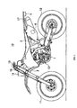
- FIG. 1 is a left side elevational view of a motorcycle 10 having a circuit according to the embodiment.
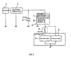
- FIG. 2 is an electrical circuit diagram of the circuit according to the embodiment of the present invention.
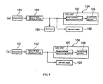
- FIG. 3 is a block diagram diagrammatically representing a flow of electricity in the circuit according to the embodiment of the present invention.
- the circuit in this embodiment is applied to a motorcycle.
- the motorcycle 10 has a front wheel 11 and a rear wheel 12.
- An engine 13 drives the rear wheel 12 and a generator 1.
- a first electrical component in the form of a CDI unit 4 is connected to a battery 3 which is removable.
- a second electrical component in the form of a tail light unit is connected to an over-voltage protecting circuit 7 of the CDI unit.
- the tail light unit includes an LED tail light 5 and an LED stop light 9 both functioning as LED lamps, and a stop switch 6.
- Other electrical components such as a head light 14, a meter 15, a front flasher 16, rear flasher 17 and so forth are provided.
- the CDI unit 4 is formed with the over-voltage protecting circuit 7 and a functional circuit 8.
- the functional circuit 8 of the CDI unit 4 boosts electric power supplied from the generator 1 and charges a capacitor (not shown) in the functional circuit 8.
- An ignition signal then makes the capacitor discharge at a burst to a primary coil of an ignition coil (not shown) . Thereby, a high voltage is applied to the primary coil of the ignition coil. The number of turns of the primary coil of the ignition coil thus is reduced to accelerate a speed of induction of a voltage in a secondary coil.
- a rectifier/regulator 2 which functions as a voltage supply controller is provided to control a power amount generated by the generator 1 so as to prevent the over-voltage from being generated.
- the rectifier/regulator 2 detects a battery voltage to control the power amount generated by the generator 1, if the motorcycle is used under a condition that the battery 3 is removed, the rectifier/regulator 2 cannot sufficiently function and the over-voltage can be applied to the functional circuit 8. Therefore, the CDI unit 4 is provided with the over-voltage protecting circuit 7 so that electric power with a stable voltage is further supplied to the functional circuit 8.
- Wirings are made in such a manner that the electric power is supplied to the LED tail light 5 through the over-voltage protecting circuit 7. Because the LED forming the LED tail light 5 is a semiconductor, it can be damaged if the over-voltage is applied thereto, in a similar manner to the functional circuit 8. However, the power is supplied through the over-voltage protecting circuit 7 under the stable condition of the voltage, and the damage can be avoided.
- the generator 1 as shown in FIG. 3(a), generates electric power and the rectifier/regulator 2 rectifies the power and regulates the voltage thereof to supply the power to the CDI unit 4 and the LED tail light 5, while charging the battery 3. Therefore, the power can be supplied from the rectifier/regulator 2 to the CDI unit 4 and the LED tail light 5 under the stable condition of the voltage (no over-voltage condition).
- the power as shown in FIG. 3(b), is supplied from the rectifier/regulator 2 to the CDI unit 4 without any charge function to the battery 3 being provided, and also is supplied to the LED tail light 5 through the over-voltage protecting circuit 7.
- the over-voltage protecting circuit 7 of the CDI unit 4 can protect the LED tail light 5 from the over-voltage condition. That is, even though the motorcycle 10 is used with the battery 3 removed, the damage of the electrical component having no over-voltage protecting circuit, particularly the LED tail light 5, can be prevented by the simple structure. Accordingly, the reliability of the electrical component can be improved without any raise in cost.
- the case in which the second electrical component having no over-voltage protecting circuit is formed with the LED tail light 5 is exemplified.
- the rear flasher 17 uses an LED lamp and the LED lamp is connected to the over-voltage protecting circuit 7 of the first electrical component, the same action and effect can be obtained.
- the case in which the first electrical component having the over-voltage protecting circuit 7 is formed with the CDI unit 4 that makes the ignition control of the engine 13 is exemplified.
- an LED lamp of the front flasher 16 or a pilot lamp (not shown) of the meter 15 as the second electrical component is connected to an over-voltage protecting circuit of another first electrical component, for example, the meter 15, the same action and effect can be obtained.
Landscapes
- Engineering & Computer Science (AREA)
- Power Engineering (AREA)
- Lighting Device Outwards From Vehicle And Optical Signal (AREA)
- Charge And Discharge Circuits For Batteries Or The Like (AREA)
- Control Of Charge By Means Of Generators (AREA)
- Control Of Voltage And Current In General (AREA)
- Combined Controls Of Internal Combustion Engines (AREA)
Applications Claiming Priority (1)
| Application Number | Priority Date | Filing Date | Title |
|---|---|---|---|
| JP2006113261A JP2007288916A (ja) | 2006-04-17 | 2006-04-17 | 電圧調整回路、および電圧調整回路を備えた自動二輪車 |
Publications (3)
| Publication Number | Publication Date |
|---|---|
| EP1848089A2 true EP1848089A2 (de) | 2007-10-24 |
| EP1848089A3 EP1848089A3 (de) | 2011-03-23 |
| EP1848089B1 EP1848089B1 (de) | 2013-05-01 |
Family
ID=38345981
Family Applications (1)
| Application Number | Title | Priority Date | Filing Date |
|---|---|---|---|
| EP07251184.3A Not-in-force EP1848089B1 (de) | 2006-04-17 | 2007-03-21 | Elektrische Schaltung und Motorrad mit einer elektrischen Schaltung |
Country Status (3)
| Country | Link |
|---|---|
| US (1) | US7764052B2 (de) |
| EP (1) | EP1848089B1 (de) |
| JP (1) | JP2007288916A (de) |
Families Citing this family (5)
| Publication number | Priority date | Publication date | Assignee | Title |
|---|---|---|---|---|
| US20140043089A1 (en) * | 2011-04-28 | 2014-02-13 | Koninklijke Philips N.V. | Digitally controlled high speed high voltage gate driver circuit |
| US9197151B2 (en) | 2013-01-05 | 2015-11-24 | Mtd Products Inc | Alternator overvoltage protection circuit |
| CN104816691A (zh) * | 2013-06-26 | 2015-08-05 | 庄景阳 | 车速信号控制整流器的断电装置 |
| CN106155154B (zh) * | 2015-03-31 | 2018-09-25 | 无锡迈尔斯通集成电路有限公司 | 一种摩托车用短路式mos调压器系统 |
| TWI665541B (zh) * | 2018-04-27 | 2019-07-11 | 三陽工業股份有限公司 | 機車電源控制方法 |
Citations (5)
| Publication number | Priority date | Publication date | Assignee | Title |
|---|---|---|---|---|
| JPH06141457A (ja) | 1992-10-20 | 1994-05-20 | Shindengen Electric Mfg Co Ltd | 磁石式交流発電機 |
| EP0684381A2 (de) | 1994-05-26 | 1995-11-29 | DUCATI ENERGIA S.p.A. | Selektives Stromversorgungsgerät für elektrische Verbraucher und Zündsystem von inneren Brennkraftmaschinen in Motorfahrzeugen |
| JPH09324732A (ja) | 1996-06-05 | 1997-12-16 | Mitsuba Corp | 点火制御装置 |
| JPH10201125A (ja) | 1996-12-27 | 1998-07-31 | Mitsuba Corp | 二輪車用発電機の電圧調節回路 |
| JP2004350441A (ja) | 2003-05-23 | 2004-12-09 | Mitsuba Corp | 自動車の電源回路 |
Family Cites Families (13)
| Publication number | Priority date | Publication date | Assignee | Title |
|---|---|---|---|---|
| US4569009A (en) * | 1984-03-05 | 1986-02-04 | Honeywell Information Systems Inc. | Switching regulator having a selectable gain amplifier for providing a selectively alterable output voltage |
| US4799126A (en) * | 1987-04-16 | 1989-01-17 | Navistar International Transportation Corp. | Overload protection for D.C. circuits |
| JPH0349598A (ja) * | 1989-07-13 | 1991-03-04 | Mitsubishi Electric Corp | 車両用交流発電機の制御装置 |
| FR2690601B1 (fr) * | 1992-04-22 | 2002-02-01 | Valeo Electronique | Platine de servitude pour la commande et/ou l'alimentation d'organes électriques de véhicules. |
| US5869907A (en) * | 1996-01-23 | 1999-02-09 | Marler; Rick A. | Modular wiring harness for a vehicle |
| US5949147A (en) * | 1996-05-24 | 1999-09-07 | Hayes Lemmerz International, Inc. | Short circuit safety audible monitor |
| US6731486B2 (en) * | 2001-12-19 | 2004-05-04 | Fairchild Semiconductor Corporation | Output-powered over-voltage protection circuit |
| JP3899984B2 (ja) * | 2002-04-09 | 2007-03-28 | 富士電機デバイステクノロジー株式会社 | 過電圧保護回路 |
| JP4175543B2 (ja) * | 2002-11-22 | 2008-11-05 | 本田技研工業株式会社 | 車両用テールランプ |
| US7162656B2 (en) * | 2003-03-24 | 2007-01-09 | Intel Corporation | Dynamic protection circuit |
| KR100817053B1 (ko) * | 2006-05-10 | 2008-03-26 | 삼성전자주식회사 | 과전압 검출 로직 및 딜레이 회로를 칩 내부에 구비하는과전압 방지 제어 회로 및 과전압 방지 제어 방법 |
| US7420355B2 (en) * | 2006-07-11 | 2008-09-02 | Artesyn Technologies, Inc. | DC-DC converter with over-voltage protection |
| US8009395B2 (en) * | 2007-11-07 | 2011-08-30 | Texas Instruments Incorporated | Methods and apparatus for over-voltage protection of device inputs |
-
2006
- 2006-04-17 JP JP2006113261A patent/JP2007288916A/ja not_active Withdrawn
-
2007
- 2007-03-21 EP EP07251184.3A patent/EP1848089B1/de not_active Not-in-force
- 2007-04-17 US US11/736,469 patent/US7764052B2/en not_active Expired - Fee Related
Patent Citations (5)
| Publication number | Priority date | Publication date | Assignee | Title |
|---|---|---|---|---|
| JPH06141457A (ja) | 1992-10-20 | 1994-05-20 | Shindengen Electric Mfg Co Ltd | 磁石式交流発電機 |
| EP0684381A2 (de) | 1994-05-26 | 1995-11-29 | DUCATI ENERGIA S.p.A. | Selektives Stromversorgungsgerät für elektrische Verbraucher und Zündsystem von inneren Brennkraftmaschinen in Motorfahrzeugen |
| JPH09324732A (ja) | 1996-06-05 | 1997-12-16 | Mitsuba Corp | 点火制御装置 |
| JPH10201125A (ja) | 1996-12-27 | 1998-07-31 | Mitsuba Corp | 二輪車用発電機の電圧調節回路 |
| JP2004350441A (ja) | 2003-05-23 | 2004-12-09 | Mitsuba Corp | 自動車の電源回路 |
Also Published As
| Publication number | Publication date |
|---|---|
| EP1848089A3 (de) | 2011-03-23 |
| US7764052B2 (en) | 2010-07-27 |
| EP1848089B1 (de) | 2013-05-01 |
| US20070241565A1 (en) | 2007-10-18 |
| JP2007288916A (ja) | 2007-11-01 |
Similar Documents
| Publication | Publication Date | Title |
|---|---|---|
| KR101743855B1 (ko) | 차량 탑재 태양 전지를 이용하는 충전 제어 장치 | |
| CN100539371C (zh) | 具有过压保护的电压调节器 | |
| CN108791134B (zh) | 蓄电池平衡方法 | |
| EP1848089A2 (de) | Elektrische Schaltung und Motorrad mit einer elektrischen Schaltung | |
| CN103796864B (zh) | 用于电驱动系统的直流变压器的控制装置和用于运行直流变压器的方法 | |
| CN104884784B (zh) | 内燃机控制电路及内燃机控制方法 | |
| CN104097596B (zh) | 机动车多电压车用电路及其运行方法和实现该方法的机构 | |
| CN101395789A (zh) | 电源系统及其方法 | |
| US20100079117A1 (en) | Field transient suppression system and method | |
| JP2003512803A (ja) | マルチ電圧搭載電源 | |
| US5617011A (en) | Method and system for limiting generator field voltage in the event of regulator failure in an automotive vehicle | |
| EP1626476A1 (de) | Fahrzeugstromversorgungssteuervorrichtung und fahrzeugstromversorgungsvorrichtung | |
| US8275504B2 (en) | Stabilization apparatus and method for stabling load voltage of vehicle | |
| CN100532828C (zh) | 电源装置 | |
| JP4143648B2 (ja) | 界磁巻線式交流回転電機装置 | |
| JP3525010B2 (ja) | 点火制御装置 | |
| KR20150116843A (ko) | 차상 전력 시스템을 위한 에너지 공급 유닛을 작동시키기 위한 방법 | |
| JP5192170B2 (ja) | 発電制御装置及び鞍乗型車両 | |
| JP2006087163A (ja) | 車両用発電制御装置 | |
| JP2008131772A (ja) | 電源装置 | |
| KR101468174B1 (ko) | 차량의 전원 제어 장치 | |
| JP5306642B2 (ja) | 発電制御装置 | |
| JP5237716B2 (ja) | 自動車用バッテリの瞬時ピーク電圧安定装置 | |
| CN101029614B (zh) | 电控燃油喷射内燃机的供电装置 | |
| KR101860107B1 (ko) | 소형엔진 충전표시장치 |
Legal Events
| Date | Code | Title | Description |
|---|---|---|---|
| PUAI | Public reference made under article 153(3) epc to a published international application that has entered the european phase |
Free format text: ORIGINAL CODE: 0009012 |
|
| 17P | Request for examination filed |
Effective date: 20070402 |
|
| AK | Designated contracting states |
Kind code of ref document: A2 Designated state(s): AT BE BG CH CY CZ DE DK EE ES FI FR GB GR HU IE IS IT LI LT LU LV MC MT NL PL PT RO SE SI SK TR |
|
| AX | Request for extension of the european patent |
Extension state: AL BA HR MK YU |
|
| PUAL | Search report despatched |
Free format text: ORIGINAL CODE: 0009013 |
|
| AK | Designated contracting states |
Kind code of ref document: A3 Designated state(s): AT BE BG CH CY CZ DE DK EE ES FI FR GB GR HU IE IS IT LI LT LU LV MC MT NL PL PT RO SE SI SK TR |
|
| AX | Request for extension of the european patent |
Extension state: AL BA HR MK RS |
|
| AKX | Designation fees paid |
Designated state(s): AT BE BG CH CY CZ DE DK EE ES FI FR GB GR HU IE IS IT LI LT LU LV MC MT NL PL PT RO SE SI SK TR |
|
| GRAP | Despatch of communication of intention to grant a patent |
Free format text: ORIGINAL CODE: EPIDOSNIGR1 |
|
| GRAS | Grant fee paid |
Free format text: ORIGINAL CODE: EPIDOSNIGR3 |
|
| GRAA | (expected) grant |
Free format text: ORIGINAL CODE: 0009210 |
|
| AK | Designated contracting states |
Kind code of ref document: B1 Designated state(s): AT BE BG CH CY CZ DE DK EE ES FI FR GB GR HU IE IS IT LI LT LU LV MC MT NL PL PT RO SE SI SK TR |
|
| REG | Reference to a national code |
Ref country code: GB Ref legal event code: FG4D |
|
| REG | Reference to a national code |
Ref country code: AT Ref legal event code: REF Ref document number: 610445 Country of ref document: AT Kind code of ref document: T Effective date: 20130515 Ref country code: CH Ref legal event code: EP |
|
| REG | Reference to a national code |
Ref country code: IE Ref legal event code: FG4D |
|
| REG | Reference to a national code |
Ref country code: DE Ref legal event code: R096 Ref document number: 602007030144 Country of ref document: DE Effective date: 20130627 |
|
| REG | Reference to a national code |
Ref country code: AT Ref legal event code: MK05 Ref document number: 610445 Country of ref document: AT Kind code of ref document: T Effective date: 20130501 |
|
| REG | Reference to a national code |
Ref country code: NL Ref legal event code: VDEP Effective date: 20130501 |
|
| REG | Reference to a national code |
Ref country code: LT Ref legal event code: MG4D |
|
| PG25 | Lapsed in a contracting state [announced via postgrant information from national office to epo] |
Ref country code: FI Free format text: LAPSE BECAUSE OF FAILURE TO SUBMIT A TRANSLATION OF THE DESCRIPTION OR TO PAY THE FEE WITHIN THE PRESCRIBED TIME-LIMIT Effective date: 20130501 Ref country code: IS Free format text: LAPSE BECAUSE OF FAILURE TO SUBMIT A TRANSLATION OF THE DESCRIPTION OR TO PAY THE FEE WITHIN THE PRESCRIBED TIME-LIMIT Effective date: 20130901 Ref country code: ES Free format text: LAPSE BECAUSE OF FAILURE TO SUBMIT A TRANSLATION OF THE DESCRIPTION OR TO PAY THE FEE WITHIN THE PRESCRIBED TIME-LIMIT Effective date: 20130812 Ref country code: LT Free format text: LAPSE BECAUSE OF FAILURE TO SUBMIT A TRANSLATION OF THE DESCRIPTION OR TO PAY THE FEE WITHIN THE PRESCRIBED TIME-LIMIT Effective date: 20130501 Ref country code: SI Free format text: LAPSE BECAUSE OF FAILURE TO SUBMIT A TRANSLATION OF THE DESCRIPTION OR TO PAY THE FEE WITHIN THE PRESCRIBED TIME-LIMIT Effective date: 20130501 Ref country code: PT Free format text: LAPSE BECAUSE OF FAILURE TO SUBMIT A TRANSLATION OF THE DESCRIPTION OR TO PAY THE FEE WITHIN THE PRESCRIBED TIME-LIMIT Effective date: 20130902 Ref country code: SE Free format text: LAPSE BECAUSE OF FAILURE TO SUBMIT A TRANSLATION OF THE DESCRIPTION OR TO PAY THE FEE WITHIN THE PRESCRIBED TIME-LIMIT Effective date: 20130501 Ref country code: GR Free format text: LAPSE BECAUSE OF FAILURE TO SUBMIT A TRANSLATION OF THE DESCRIPTION OR TO PAY THE FEE WITHIN THE PRESCRIBED TIME-LIMIT Effective date: 20130802 Ref country code: AT Free format text: LAPSE BECAUSE OF FAILURE TO SUBMIT A TRANSLATION OF THE DESCRIPTION OR TO PAY THE FEE WITHIN THE PRESCRIBED TIME-LIMIT Effective date: 20130501 |
|
| PG25 | Lapsed in a contracting state [announced via postgrant information from national office to epo] |
Ref country code: CY Free format text: LAPSE BECAUSE OF FAILURE TO SUBMIT A TRANSLATION OF THE DESCRIPTION OR TO PAY THE FEE WITHIN THE PRESCRIBED TIME-LIMIT Effective date: 20130501 Ref country code: PL Free format text: LAPSE BECAUSE OF FAILURE TO SUBMIT A TRANSLATION OF THE DESCRIPTION OR TO PAY THE FEE WITHIN THE PRESCRIBED TIME-LIMIT Effective date: 20130501 Ref country code: BG Free format text: LAPSE BECAUSE OF FAILURE TO SUBMIT A TRANSLATION OF THE DESCRIPTION OR TO PAY THE FEE WITHIN THE PRESCRIBED TIME-LIMIT Effective date: 20130801 |
|
| PG25 | Lapsed in a contracting state [announced via postgrant information from national office to epo] |
Ref country code: LV Free format text: LAPSE BECAUSE OF FAILURE TO SUBMIT A TRANSLATION OF THE DESCRIPTION OR TO PAY THE FEE WITHIN THE PRESCRIBED TIME-LIMIT Effective date: 20130501 |
|
| PG25 | Lapsed in a contracting state [announced via postgrant information from national office to epo] |
Ref country code: DK Free format text: LAPSE BECAUSE OF FAILURE TO SUBMIT A TRANSLATION OF THE DESCRIPTION OR TO PAY THE FEE WITHIN THE PRESCRIBED TIME-LIMIT Effective date: 20130501 Ref country code: BE Free format text: LAPSE BECAUSE OF FAILURE TO SUBMIT A TRANSLATION OF THE DESCRIPTION OR TO PAY THE FEE WITHIN THE PRESCRIBED TIME-LIMIT Effective date: 20130501 Ref country code: CZ Free format text: LAPSE BECAUSE OF FAILURE TO SUBMIT A TRANSLATION OF THE DESCRIPTION OR TO PAY THE FEE WITHIN THE PRESCRIBED TIME-LIMIT Effective date: 20130501 Ref country code: SK Free format text: LAPSE BECAUSE OF FAILURE TO SUBMIT A TRANSLATION OF THE DESCRIPTION OR TO PAY THE FEE WITHIN THE PRESCRIBED TIME-LIMIT Effective date: 20130501 Ref country code: EE Free format text: LAPSE BECAUSE OF FAILURE TO SUBMIT A TRANSLATION OF THE DESCRIPTION OR TO PAY THE FEE WITHIN THE PRESCRIBED TIME-LIMIT Effective date: 20130501 |
|
| PG25 | Lapsed in a contracting state [announced via postgrant information from national office to epo] |
Ref country code: IT Free format text: LAPSE BECAUSE OF FAILURE TO SUBMIT A TRANSLATION OF THE DESCRIPTION OR TO PAY THE FEE WITHIN THE PRESCRIBED TIME-LIMIT Effective date: 20130501 Ref country code: NL Free format text: LAPSE BECAUSE OF FAILURE TO SUBMIT A TRANSLATION OF THE DESCRIPTION OR TO PAY THE FEE WITHIN THE PRESCRIBED TIME-LIMIT Effective date: 20130501 Ref country code: RO Free format text: LAPSE BECAUSE OF FAILURE TO SUBMIT A TRANSLATION OF THE DESCRIPTION OR TO PAY THE FEE WITHIN THE PRESCRIBED TIME-LIMIT Effective date: 20130501 |
|
| PLBE | No opposition filed within time limit |
Free format text: ORIGINAL CODE: 0009261 |
|
| STAA | Information on the status of an ep patent application or granted ep patent |
Free format text: STATUS: NO OPPOSITION FILED WITHIN TIME LIMIT |
|
| 26N | No opposition filed |
Effective date: 20140204 |
|
| REG | Reference to a national code |
Ref country code: DE Ref legal event code: R097 Ref document number: 602007030144 Country of ref document: DE Effective date: 20140204 |
|
| PG25 | Lapsed in a contracting state [announced via postgrant information from national office to epo] |
Ref country code: LU Free format text: LAPSE BECAUSE OF FAILURE TO SUBMIT A TRANSLATION OF THE DESCRIPTION OR TO PAY THE FEE WITHIN THE PRESCRIBED TIME-LIMIT Effective date: 20140321 |
|
| REG | Reference to a national code |
Ref country code: CH Ref legal event code: PL |
|
| REG | Reference to a national code |
Ref country code: IE Ref legal event code: MM4A |
|
| PG25 | Lapsed in a contracting state [announced via postgrant information from national office to epo] |
Ref country code: IE Free format text: LAPSE BECAUSE OF NON-PAYMENT OF DUE FEES Effective date: 20140321 Ref country code: LI Free format text: LAPSE BECAUSE OF NON-PAYMENT OF DUE FEES Effective date: 20140331 Ref country code: CH Free format text: LAPSE BECAUSE OF NON-PAYMENT OF DUE FEES Effective date: 20140331 |
|
| REG | Reference to a national code |
Ref country code: FR Ref legal event code: PLFP Year of fee payment: 9 |
|
| PGFP | Annual fee paid to national office [announced via postgrant information from national office to epo] |
Ref country code: DE Payment date: 20150317 Year of fee payment: 9 |
|
| PGFP | Annual fee paid to national office [announced via postgrant information from national office to epo] |
Ref country code: GB Payment date: 20150318 Year of fee payment: 9 Ref country code: FR Payment date: 20150309 Year of fee payment: 9 |
|
| PG25 | Lapsed in a contracting state [announced via postgrant information from national office to epo] |
Ref country code: MT Free format text: LAPSE BECAUSE OF FAILURE TO SUBMIT A TRANSLATION OF THE DESCRIPTION OR TO PAY THE FEE WITHIN THE PRESCRIBED TIME-LIMIT Effective date: 20130501 |
|
| PG25 | Lapsed in a contracting state [announced via postgrant information from national office to epo] |
Ref country code: MC Free format text: LAPSE BECAUSE OF FAILURE TO SUBMIT A TRANSLATION OF THE DESCRIPTION OR TO PAY THE FEE WITHIN THE PRESCRIBED TIME-LIMIT Effective date: 20130501 |
|
| PG25 | Lapsed in a contracting state [announced via postgrant information from national office to epo] |
Ref country code: TR Free format text: LAPSE BECAUSE OF FAILURE TO SUBMIT A TRANSLATION OF THE DESCRIPTION OR TO PAY THE FEE WITHIN THE PRESCRIBED TIME-LIMIT Effective date: 20130501 Ref country code: HU Free format text: LAPSE BECAUSE OF FAILURE TO SUBMIT A TRANSLATION OF THE DESCRIPTION OR TO PAY THE FEE WITHIN THE PRESCRIBED TIME-LIMIT; INVALID AB INITIO Effective date: 20070321 |
|
| REG | Reference to a national code |
Ref country code: DE Ref legal event code: R119 Ref document number: 602007030144 Country of ref document: DE |
|
| GBPC | Gb: european patent ceased through non-payment of renewal fee |
Effective date: 20160321 |
|
| REG | Reference to a national code |
Ref country code: FR Ref legal event code: ST Effective date: 20161130 |
|
| PG25 | Lapsed in a contracting state [announced via postgrant information from national office to epo] |
Ref country code: GB Free format text: LAPSE BECAUSE OF NON-PAYMENT OF DUE FEES Effective date: 20160321 Ref country code: DE Free format text: LAPSE BECAUSE OF NON-PAYMENT OF DUE FEES Effective date: 20161001 Ref country code: FR Free format text: LAPSE BECAUSE OF NON-PAYMENT OF DUE FEES Effective date: 20160331 |