EP1848199A1 - Appareil d'imagerie et procédé pour le traitement des signaux d'image - Google Patents
Appareil d'imagerie et procédé pour le traitement des signaux d'image Download PDFInfo
- Publication number
- EP1848199A1 EP1848199A1 EP07251654A EP07251654A EP1848199A1 EP 1848199 A1 EP1848199 A1 EP 1848199A1 EP 07251654 A EP07251654 A EP 07251654A EP 07251654 A EP07251654 A EP 07251654A EP 1848199 A1 EP1848199 A1 EP 1848199A1
- Authority
- EP
- European Patent Office
- Prior art keywords
- signal
- processing
- image
- image signal
- output
- Prior art date
- Legal status (The legal status is an assumption and is not a legal conclusion. Google has not performed a legal analysis and makes no representation as to the accuracy of the status listed.)
- Withdrawn
Links
Images


Classifications
-
- H—ELECTRICITY
- H04—ELECTRIC COMMUNICATION TECHNIQUE
- H04N—PICTORIAL COMMUNICATION, e.g. TELEVISION
- H04N23/00—Cameras or camera modules comprising electronic image sensors; Control thereof
- H04N23/95—Computational photography systems, e.g. light-field imaging systems
-
- H—ELECTRICITY
- H04—ELECTRIC COMMUNICATION TECHNIQUE
- H04N—PICTORIAL COMMUNICATION, e.g. TELEVISION
- H04N23/00—Cameras or camera modules comprising electronic image sensors; Control thereof
- H04N23/80—Camera processing pipelines; Components thereof
- H04N23/82—Camera processing pipelines; Components thereof for controlling camera response irrespective of the scene brightness, e.g. gamma correction
Definitions
- the present invention relates to an imaging apparatus and a method of processing an image signal.
- FIG. 1 shows a configuration of a past imaging apparatus 10.
- the imaging apparatus 10 has an imaging unit 20, a signal-processing unit 30, and an output unit 40.
- An image pickup device 21 in the imaging unit 20 is driven by a driving portion 22 and produces an analog image signal SVa based on an image of a subject to supply an analog-signal-processing portion 23 with the produced image signal SVa.
- the analog-signal-processing portion 23 performs various kinds of signal processing such as noise reduction on the image signal SVa to produce a processed image signal SVb and supplies an A/D converter 24 with the processed image signal SVb.
- the A/D converter 24 receives the image signal SVb and converts it to a digital image signal DVa.
- a color-control-processing portion 31 in the signal-processing unit 30 receives the digital image signal DVa and performs any processing such as improvement of color reproductivity on the digital image signal DVa to produce a color-controlled image signal DVb.
- a nonlinear-processing portion 32 receives the color-controlled image signal DVb and performs any processing such as dynamic range compression processing and gamma processing on the image signal DVb to produce a non-linear-processed image signal DVc.
- a detail-processing portion 33 receives the non-linear-processed image signal DVc and performs any processing such as contour compensation on the image signal DVc to produce an image signal DVd.
- the output unit 40 receives the image signal DVd from the signal-processing unit 30 and converts it to a signal having a transmission format corresponding to image-displaying device and/or image-recording device to produce an output signal DVout.
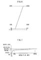
- FIG. 2 shows a relationship between intensity of light input to the image pickup device 21 and the imaged signal SVa output from the image pickup device 21.
- the A/D converter 24 is thus designed for maintaining a dynamic range of 600 % or more corresponding to the image pickup device 21.
- the dynamic range compression processing is then performed so that the image signal can have a signal level corresponding to any broadband standards.
- FIG. 3 shows Knee compensation processing by which an image portion having intensity of input from 80 % to 600 % is compressed to an image portion having output level from 80 % to 109 % (white clip level).
- any gamma compensation is performed so that an image signal can correspond to input/output properties of display device used in the image-displaying device, not shown.
- display device used in the image-displaying device
- nonlinear processing such that its input/output property can become convex upwardly, namely, be over compensated on a region of the intensity of input of 80 % or less.
- Japanese Patents Nos. 2884384 and 2067650 and Japanese Patent Application Publication No. H04-319871 have respectively disclosed that the nonlinear processing such as the Knee compensation or the gamma compensation can provide an image having any subjective fine picture quality.
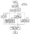
- FIG. 4 illustrates a procedure for such the image processing.
- Step ST1 by using an image pickup apparatus, an image of subject is shot to produce an image signal.
- a recording medium stores the image signal thus produced.
- Step ST2 the image signal is captured.
- the stored image signal is read from the recording medium and reproduced.
- a post-production processing apparatus which is not shown, writes the reproduced image signal in its memory, its hard disk or the like.
- Steps ST3 through ST6 any edition processing such as cut edition, exposure compensation and/or tone correction, color tuning, and special effects is performed on the image signal when necessary.
- the edited image signal is recorded, at Step ST7, on a recording medium or stored in a server or the like.
- an image shot at an adequate amount of exposure is equal to an image having a dynamic range of about 600 % so that an imaging apparatus using image pickup device may be required for having any performance equal to that of the film camera.
- This enables to be realized an image shot by the image pickup apparatus without performing the Knee compensation, the gamma compensation and the like.
- post-production processing that has any performance equal to that of the film camera is performed, it is possible to provide an image having an excellent picture quality because no Knee compensation or no gamma compensation is performed on this image.
- an imaging apparatus containing an imaging unit that images a subject and produces an image signal, a signal-processing unit that performs dynamic range compression processing on the image signal, a first output unit that produces a first output signal based on the image signal processed in the signal-processing unit, a signal-producing unit that produces a signal including the image signal and any processing information that indicates which dynamic range compression processing is performed in the signal-processing unit, and a second output unit that produces a second output signal based on the signal produced in the signal-producing unit.
- a method of processing an image signal includes a imaging step of imaging a subject and producing an image signal, a signal-processing step of performing dynamic range compression processing on the image signal, a first output step of producing a first output signal based on the image signal processed in the signal-processing step, a signal-producing step of producing a signal including the image signal and processing information that indicates which dynamic range compression processing is performed in the signal-processing step, and a second output step of producing a second output signal based on the signal produced in the signal-producing step.
- a program product of processing an image signal which allows a computer to perform the above method of processing an image signal.
- the Knee compensation is performed on the image signal produced by shooting the subject to compress a signal level of a high brightness portion of the subject.
- various kinds of pieces of processing information such as Knee point and Knee slope are used.
- the Knee compensation is performed using a compensation table, information that indicates which compensation table is used is utilized as the processing information.
- information that indicates which signal processing is performed in the other signal processing is utilized as the processing information.
- any information such that which broken line approximation or which compensation table is used in the gamma compensation, which gain adjustment or which masking coefficient is used in the color tuning, or which filter setting is used in contour compensation is utilized as the processing information.
- the processing information is not only added but also an amount of data in the second output signal is reduced.
- the amount of data in the second output signal is reduced by, for example, making bit width of the image signal narrow or extracting an image signal so that information of a region which includes a small amount of information can be supplemented by the first output signal.
- the amount of data in the second output signal can be also reduced by coding the image signal. Weighting the image signal on reduction of the amount of the data allows the amount of the data to be adjusted so that amount of data can be reduced on the important potion of the image.
- dynamic range compression processing is performed on the image signal produced by shooting a subject and a first output signal is then produced based on the image signal processed by the dynamic range compression processing.
- the processing information that indicates which dynamic range compression processing is performed is added to the produced image signal and the second output signal is then produced based on the image signal adding such the processing information.
- the second output signal enables an image having an excellent picture quality to be obtained even if the post-production processing such that an editor demands increase in exposure compensation and an alteration of gamma curve is performed.
- Using the second output signal also enables times of nonlinear processing to be limited so that an image having an excellent picture quality can be produced.
- using the first output signal enables check of the image of the subject on shooting the subject to be easily performed and an image to be easily designed before the post-production processing. Since the second output signal includes the processing information, it is possible to obtain an image of the subject, even when using the second output signal, that a user desires on shooting the subject when the processing information is used in the post-production processing.
- FIG. 5 shows a configuration of an imaging apparatus 100 according to a first embodiment of the invention.
- the imaging apparatus 100 has an imaging unit 120, a signal-processing unit 130, a first output unit 140, a signal-producing unit 150, a second output unit 160, a control unit 170, and a user interface unit 180.
- An image pickup device 121 in the imaging unit 120 is made of complementary metal oxide semiconductor (CMOS) element or charge coupled devices (CCD) element.
- the image pickup device 121 is driven by a driving portion 122 and produces an analog image signal SVa, for example, an analog signal on the three primary colors, based on an image of a subject to supply an analog-signal-processing portion 123 with the produced image signal SVa.
- the analog-signal-processing portion 123 performs on the image signal SVa various kinds of signal processing such as noise reduction on the image signal SVa, an amplification of the noise-reduced signal, and setting of black level to the amplified signal.
- the analog-signal-processing portion 123 performs the signal processing on the image signal SVa to produce an image signal SVb and supplies an A/D converter 124 with the processed image signal SVb.
- the A/D converter 124 receives the image signal SVb and converts it to a digital image signal DVa.
- the A/D converter 124 supplies the signal-processing unit 130 and the signal-producing unit 150 with the digital image signal DVa.
- a color-control-processing portion 131 in the signal-processing unit 130 receives the digital image signal DVa and performs on the digital image signal DVa any processing such as white balance adjustment, hue adjustment, and linear matrix processing to reproduce color adequately or so that a user desires it.
- the color-control-processing portion 131 performs such the color reproductivity on the digital image signal DVa to produce a color-controlled image signal DVb and supplies a nonlinear-processing portion 132 with the image signal DVb.
- the nonlinear-processing portion 132 receives the image signal DVb and performs any processing such as dynamic range compression processing and gamma compensation for constant representation on the image signal DVb to produce a non-linear-processed image signal DVc.
- the nonlinear-processing portion 132 supplies a detail-processing portion 133 with the image signal DVc.
- the detail-processing portion 133 receives the image signal DVc and performs any processing such as contour compensation on the image signal DVc to produce an image signal DVd.
- the detail-processing portion 133 supplies the first output unit 140 with the image signal DVd.
- the first signal-processing unit 130 supplies the signal-producing unit 150 with processing information FP that indicates which signal processing is performed in the signal-processing unit 130.
- the first output unit 140 receives the image signal DVd from the signal-processing unit 130 and converts it to a signal having a transmission format corresponding to image-displaying device and/or an image-recording device to produce a first output signal DVout. If a brightness signal or a color difference signal is used as the first output signal DVout, the first output unit 140 performs matrix operation thereon.
- the signal-producing unit 150 adds the processing information FP that indicates which signal processing is performed in the signal-processing unit 130 to the image signal DVa received from the imaging unit 120 to produce a signal DWa and supply the second output unit 160 with it. If the second output unit 160 outputs the signal DWA including the processing information FP when a transmission path has not a sufficient transmission rate, it is difficult to transmit the image signal DVa for each frame. Such the transmission path, however, has a sufficient transmission rate is expensive. In this embodiment, in order to prevent the configuration of the imaging apparatus from being increased in costs, the signal-producing unit 150 performs any decreasing processing in an amount of data on the image signal DVa.
- a bit change portion 151 in the signal-producing unit 150 performs such the decreasing processing in an amount of data on the image signal DVa.
- the bit change portion 151 narrows width in bits of the image signal DVa received from the A/D converter 124 and changes it to an image signal DVg that has a dynamic range wider than that of the image signal DVd output from the signal-processing unit 130 and less amount of data than that of the image signal DVa.
- the bit change portion 151 supplies the processing-information-adding portion 152 with the image signal DVg.
- the processing-information-adding portion 152 adds the processing information FP to the image signal DVg to produce the signal DWa and supplies he second output unit 160 with the signal DWa.
- the second output unit 160 receives the signal DWa from the signal-producing unit 150 and converts the signal DWa to a signal having a transmission format corresponding to an apparatus for the post-production processing to produce a second output signal DWout.
- the control unit 170 in connected to the user interface unit 180.
- the user interface unit 180 supplies the control unit 170 with an operation signal PS such as a signal based on user's operation and a signal received from any outer control device, not shown.
- the control unit 170 produces a control signal CT based on the operation signal PS so that the imaging apparatus 100 can operate corresponding to the operation signal PS received from the user interface unit 180 and supplies various units with the control signal CT.
- the control unit 170 can supply the signal-producing unit 150 with the processing information FP if the control unit 170 sets various kinds of signal processing in the signal-processing unit 130. If any processing to be performed in the signal-processing unit 130 is fixed, the signal-producing unit 150 may store previously the processing information FP that indicates which signal processing is performed in the signal-processing unit 130.
- the first output unit 140 in the imaging apparatus 100 produces the output signal DVout using a component signal with a width in 10 bits. It is also supposed that in such the component signal with a width in 10 bits, namely, a brightness signal or a signal on the three primary colors with a width in 10 bits, a black level (0 %) is set at 64 levels and a white peak level (100 %) is set at 940 levels. It is further supposed that a level of zero signal in the color difference signal is set at 512 levels.
- the A/D converter 124 performs an A/D conversion concerning a width in 14 bits so that the digital image signal DVa corresponding to the image signal SVb can be produced even when the received image signal SVb is about 600 %. Even if performing the A/D conversion concerning a width in 14 bits when its resolution equals to a width in 10 bits, it is difficult to process an image signal having signal levels corresponding to a width in 14 bits if using its dynamic range of a width in 10 bits effectively.
- an image signal corresponding to a width in 14 bits has signal levels of 0 through 16383 but if its resolution equals to a width in 10 bits, its 600 % is set at 5320 levels when the black level is set at 64 levels so that its dynamic range is not used effectively.
- the A/D converter 124 can use its dynamic range effectively by enhancing its resolution to a high level. For example, by enhancing its resolution, the black level (0 %) is set at 170 levels and the white peak level (100 %) is set at 2506 levels, as shown in FIG. 6. In this case, the maximum level of the image signal corresponding to a width in 14 bits is set at 16383 levels, which correspond to 697 %. This enables signal levels of the image signal to be represented using such the dynamic range effectively.
- the A/D converter 124 converts the received image signal SVb to the image signal DVa with a width in 14 bits.
- the color-control-processing portion 131 of the signal-processing unit 130 performs any processing such as white balance setting, linear matrix processing, hue adjustment and the like.
- white balance setting a gain on the image signal can be adjusted so that a white subject can be represented white at adequate color temperature.
- linear matrix processing a matrix operation between the image signal and masking coefficient is carried out to perform color control processing so that its color reproductivity can be enhanced.
- hue adjustment hue discrimination is performed and by using a result of the hue discrimination, a gain on the image signal can be adjusted so that a level of the specified hue region can become a desired level.
- a nonlinear-processing portion 132 performs a dynamic range compression processing and a gamma compensation using the image signal DVb received from the color-control-processing portion 131.
- FIG. 7 illustrates operations of the nonlinear-processing portion 132 and a relationship between intensity of input and output level of the image signal DVc output from the nonlinear-processing portion 132.
- the nonlinear-processing portion 132 performs Knee compensation as the dynamic range compression processing and compresses a level of the signal when intensity of input is reached at a point that is a Knee point level or more.
- the nonlinear-processing portion 132 also performs white clip processing by which when a level of the signal when intensity of input is reached at a point that is a white clip point (about 109 %) or more, the level of the signal is limited to the white clip point.
- the nonlinear-processing portion 132 performs the dynamic range compression processing on the image signal to narrow its width in bits, for example, to a width in 10 bits, and produce the signal with width in 10 bits.
- FIG. 7 shows the Knee compensation in which if setting the Knee point at 80 %, the white clip point can be set at 600 % of the intensity of input.
- the output level of the image signal DVc indicates 765 levels and if the intensity of input is 600 % or more, the output level of the image signal DVc indicates 1023 levels. It is to be noted that if Knee slope is steep (if an amount of compensation is small), the white clip point appears a point of the intensity of input that is less than 600 %.
- the nonlinear-processing portion 132 performs gamma compensation corresponding to input-output characteristics of display device used in the image-display device.
- the nonlinear-processing portion 132 may perform black gamma compensation so that tone of a low brightness portion is compensated.
- the black gamma compensation such that hue in a dark image portion, for example, a region GA of the intensity of input from 0 % to 20 %, can be richly represented is shown.
- the nonlinear-processing portion 132 uses a broken line approximation or a compensation table, for example. If using the broken line approximation, when a broken line point or an inclination of the broken line alters, characteristics of the Knee compensation or the gamma compensation can alter. If using the compensation table, when various kinds of compensation tables such as the Knee point, the Knee slope, the gamma curve, upper-limit level of the black gamma and the like are previously prepared, nonlinear processing such that any one of the compensation table is selected and used is carried out.
- a broken line approximation when a broken line point or an inclination of the broken line alters, characteristics of the Knee compensation or the gamma compensation can alter.
- the compensation table when various kinds of compensation tables such as the Knee point, the Knee slope, the gamma curve, upper-limit level of the black gamma and the like are previously prepared, nonlinear processing such that any one of the compensation table is selected and used is carried out.
- a detail-processing portion 133 is constituted of a line memory and a filter.
- the detail-processing portion 133 extracts horizontal and vertical contour potions from the image signal DVc and performs contour compensation by adding signal components of the extracted contour potions to the image signal.
- contour compensation frequency components of the contour potions to be extracted can be adjusted by changing characteristics of the filter.
- a level of intensity of the contour can be also adjusted by adjusting and adding the signal levels of the extracted contour potions.
- the first output unit 140 performs any output processing on the image signal DVd on which the contour compensation has been performed. For example, if the imaging apparatus 100 outputs a brightness signal and a color difference signal to image-displaying device and/or image-recording device, the first output unit 140 performs matrix operation on the image signal DVd to produce the brightness signal and the color difference signal. The first output unit 140 converts the produced brightness and color difference signals to signals corresponding to a transmission format and outputs them. For example, the first output unit 140 outputs them as output signals DVout having a format of high definition serial data interface (HD-SDI) 10 bit single link 4:2:2.
- HDMI high definition serial data interface
- the bit change portion 151 in the signal-producing unit 150 receives the image signal DVa from the A/D converter 124 and decreases an amount of data on the image signal DVa.
- the bit change portion 151 changes bits in the image signal DVa so that its dynamic range wider than that of the output signal DVout to be supplied to the image-display device or the image-recording device can be kept.
- FIG. 8 illustrates operations of the bit change portion 151. For example, the bit change portion 151 deletes lower-most two bits from the image signal DVa to produce an image signal DVg with a width in 12 bits.
- the bit change portion 151 supplies the processing-information-adding portion 152 with the image signal DVg. In FIG.
- the bit change portion 151 may change bits in the image signal DVa to a signal with a width in 12 bits in which a resolution of image signal with a width in 10 bits is halved so that its post-production processing can be easily realized.
- the intensity of input of 0 % corresponds to 32 levels and the intensity of input of 928 % corresponds to 4098 levels that are maximum level of the signal with a width in 12 bits.
- the signal-producing unit 150 may performs bit change so that the intensities of input from 0 % to 600 % can correspond to signal levels from 0 to 4098 levels. In this moment, its color tone reproductivity becomes about 0.15 %/bit, thereby enabling to be obtained the same color tone reproductivity as that of a signal with a width in 10 bits in which, for example, the black level of 0 % is set at 64 levels and the white peak level is set at 940 levels. Its color tone reproductivity is improved 26 times as much as a compressed portion of the image signal in a case where the Knee compensation is performed on the image signal so that the intensity of input from 80 % to 600 % can be compressed to the intensity of input from 80 % to 100 %.
- the processing-information-adding portion 152 adds the processing information FP that indicates which signal processing is performed in the color-control-processing portion 131, the nonlinear-processing portion 132, and the detail-processing portion 133, to the image signal DVg received from the bit change portion 401 to produce the signal DWa.
- the processing-information-adding portion 152 supplies the second output unit 160 with the signal DWa. For example, if the white balance adjustment, the hue adjustment, the linear matrix processing and the like are performed in the color-control-processing portion 131, information concerning how gain is adjusted in the white balance adjustment, how masking coefficient is used in an operation of the linear matrix processing, how gain is adjusted in the hue adjustment, and the like is added thereto as the processing information FP.
- the Knee compensation or the gamma compensation is performed in the nonlinear-processing portion 132, information concerning which Knee point or Knee slope is used in the Knee compensation, which compensation table is used in the Knee compensation, which broken line approximation or compensation table is used in the gamma compensation, and the like is added thereto as the processing information FP.
- the contour compensation is performed in the detail-processing portion 133, information concerning filter setting condition, gain when adding a signal indicating contour components, and the like is added thereto as the processing information FP.
- Such the processing information FP is inserted within a blank period of time in an image signal, for example, a blanking interval.
- the processing information FP can be inserted into a region of the image signal into which a digital audio signal, auxiliary data, and the like are inserted.
- the second output unit 160 receives the signal DWa from the signal-producing unit 150 and converts it to the output signal DWout with a transmission format corresponding to a post-production processing apparatus to output it. For example, if using the HD-SDI, four links is used because the image signal DVg has a width in 12 bits.
- the second output unit 160 can communicate utilizing any communication standards for communication in a network at a transmission rate of 10 G bits/second or more, Internet small computer system interface (iSCSI) for communication of SCSI commands used for communication between storage device and a computer via a network, a fiber channel that is standardized as one of the data transmission systems for connecting a computer with peripheral equipment, and the like.
- iSCSI Internet small computer system interface
- the imaging apparatus 100 outputs the output signal DVout to which the dynamic range compression processing has been performed as well as it outputs the output signal DWout wherein the processing information FP is added to an image signal to which no dynamic range compression processing has been performed.
- the imaging apparatus 100 can provide an image having an excellent picture quality even if any post-production processing that is identical to that of a case where film camera is used is performed. For example, if an editor demands increase in exposure compensation and an alteration of gamma curve, the imaging apparatus 100 can provide an image having less reduced picture quality.
- any nonlinear processing does not exert on the output signal DWout, it is possible to decrease times of nonlinear processing as compared by a case where processing is performed using the output signal DVout, thereby enabling an image having an excellent picture quality to be provided. Since an image having a wider dynamic range is provided when the output signal DWout is used, any color tone remains even if an image contains a subject (sun, light or the like) having a high brightness, thereby enabling a natural image representation to be realized.
- the imaging apparatus 100 also outputs the output signal DVout to which the dynamic range compression processing is performed so that if using the output signal DVout, it is possible to check an image for shooting easily. If the output signal DVout is recorded, it is possible to decide how an image is configured easily before the post-production processing.
- the post-production-processing apparatus may perform any processing on a portion of an image where the post-production processing is not required using the output signal DVout as it is, thereby enabling edition processing to be efficiently performed.
- the output signal DWout includes the processing information FP so that if using the processing information FP, it is possible to provide an image that a user desires at shooting, namely, an image with color reproductivity or gamma property at shooting when any signal processing is performed based on the processing information FP even if the post-production processing is performed using the output signal DWout.
- the bit change portion 151 of the signal-producing unit 150 has decreased an amount of data by deleting lower-most two bits from the image signal DVa received from the A/D converter 124 to produce an image signal DVg with a width in 12 bits, an image having a higher intensity of input is evenly treated as an image having a lower intensity of input is done.
- the image having a higher intensity of input can be treated as less weighty than the image having a lower intensity of input.
- the image having a lower intensity of input can be treated as less weighty than the image having a higher intensity of input.
- a portion of the image where the person, the building or the like is shot has more weight than a portion of the image where the clear sky or the like is shot as a background that has a higher intensity of input.
- Such the portion of the image where the clear sky or the like is shot is not susceptible even if it is less weighted.
- FIG. 9 illustrates a configuration of the imaging apparatus 200.
- like reference numbers refer to like elements of the imaging apparatus 100 shown in FIG. 5, detailed description of which will be deleted.
- a weighting bit change portion 251 of the signal-producing unit 150 decreases an amount of data of the image signal DVa by weighting when the weighting bit change portion 251 decreases an amount of data by changing the image signal DVa received from the A/D converter 124 with a width in 14 bits to the image signal DVg with a width in 12 bits.
- FIG. 10 illustrates operations of the weighting bit change portion 251. As shown in FIG. 10, the weighting bit change portion 251 weights the image signal DVa using, for example, logarithm function, irrational function or the like so that when the intensity of input is high, its resolution can be widely lowered as compared with a case where its resolution when intensity of input is low is done.
- the resolution may be shifted for each region. For example, in a region of the intensity of input below 400 %, fine resolution is available while in a region of the intensity of input of 400 % or more, coarse resolution is available. In such a case, it is possible to lower color tone reproductivity of a high brightness portion of the image and raise color tone reproductivity of a more frequently use portion of the image. If the weighting is performed so that the resolution of the important region is raised, it is possible to improve color tone reproductivity of the important region.
- the weighting bit change portion 251 supplies the processing-information-adding portion 152 with weighting information FQa that indicates which weighting is performed in the weighting bit change portion 251.
- the processing-information-adding portion 152 receives the weighting information FQa and adds the weighting information FQa as the processing information to the image signal DVg. If the control unit 170 controls the weighting by the weighting bit change portion 251, the control unit 170 can supply the processing-information-adding portion 152 with the weighting information FQa.
- weighting restrains picture quality of the important portion of the intensity of input from being reduced because finer resolution is set on the portion even if an amount of data of this portion is decreased by narrowing a width in bits thereof. Adding the weighting information allows to be properly determined how intensity of input the signal level of the output signal DWout corresponds to if the post-production processing is performed using the output signal DWout.
- FIG. 11 illustrates a configuration of the imaging apparatus 300.
- like reference numbers refer to like elements of the imaging apparatus 100 shown in FIG. 5, detailed description of which will be deleted.
- the nonlinear-processing portion 132 thus supplies an extracting bit change portion 351 of the signal-producing unit 150 with nonlinear processing information FC that indicates the Knee point, an upper limit level of black gamma, which is gamma compensation on a dark portion of an image.
- the extracting bit change portion 351 extracts information on a region where the intensity of input is higher than the Knee point based on the nonlinear processing information FC and changes the extracted information with width in 14 bits to that with width in 12 bits to decrease an amount of data thereof.
- the extracting bit change portion 351 extracts information on a region where the intensity of input reaches the upper limit level of the black gamma based on the nonlinear processing information FC and changes the extracted information with width in 14 bits to that with width in 12 bits to decrease an amount of data thereof.
- FIG. 12 illustrates operations of the extracting bit change portion 351.
- a signal having the intensity of 20 % or less with width in 14 bits and a signal having the intensity of 80 % or more with width in 14 bits are converted to those with width in 12 bits, except for information on a region from 20 % to 80 % as shown in FIG. 12 in which an excellent color tone reproductivity is obtained, thereby decreasing an amount of data thereof.
- the extracting bit change portion 351 supplies the processing-information-adding portion 152 with extracting control information FQb that indicates how information is extracted in the extracting bit change portion 351.
- the processing-information-adding portion 152 receives the extracting control information FQb and adds the extracting control information FQb as the processing information to the image signal DVg. If the control unit 170 controls the extract condition in the extracting bit change portion 351, the control unit 170 can supply the processing-information-adding portion 152 with the extracting control information FQb.
- FIG. 13 illustrates a configuration of the imaging apparatus 400.
- like reference numbers refer to like elements of the imaging apparatus 100 shown in FIG. 5, detailed description of which will be deleted.
- An extracting and weighting bit change portion 451 performs extraction processing based on the nonlinear processing information FC like the extracting bit change portion 351 and weights the extracted signal like the weighting bit change portion 251 to change a signal with width in 14 bits to a signal with width in 12 bits, thereby decreasing an amount of data thereof.
- FIG. 14 illustrates operations of the extracting and weighting bit change portion 451. For example, if the Knee point is set at 80 % of the intensity of input and the upper limit level of the black gamma is set at 20 % thereof, information on the intensity of input of 20 % or less and information on the intensity of 80 % or more are extracted and the extracted signal with width in 14 bits is converted to that with width in 12 bits as shown in FIG.
- the weighting information FQa and the extracting control information FQb are supplied to the processing-information-adding portion 152 in which they are added to the image signal DVg as the processing information FP.
- information lacked in the output signal DVout can be supplemented so that fine resolution is available for a more important region and coarse resolution is available for a less important region.
- FIG. 15 illustrates a configuration of the imaging apparatus 500.
- the bit change portion 151 outputs the image signal DVg to a signal-compressing portion 551.
- the weighting bit change portion 251, the extracting bit change portion 351, or the extracting and weighting bit change portion 451 instead of the bit change portion 151 can output the image signal DVg.
- the bit change portion 151 (weighting bit change portion 251, the extracting bit change portion 351, or the extracting and weighting bit change portion 451) supplies an encoding portion 550 with the image signal DVg.
- the encoding portion 550 performs matrix operation using the image signal DVg to produce a brightness signal Y, color difference signals Cr, Cb.
- the encoding portion 550 supplies the signal-compressing portion 551 with the produced signals.
- the signal-compressing portion 551 compresses the image signal DVg received from the bit change portion 151 (weighting bit change portion 251, the extracting bit change portion 351, or the extracting and weighting bit change portion 451) or the brightness signal Y and the color difference signals Cr, Cb produced in the encoding portion 550.
- the compression processing processing such that its redundancy can be deleted by utilizing a spatial correlation (for example, block encoding), processing such that its redundancy can be deleted by utilizing a temporal correlation (for example, motion-compensating inter-frame coding), and processing such that an amount of data can be decreased by utilizing an appearance of code (for example, Huffman coding or entropy coding) are used.
- the signal-compressing portion 551 supplies the processing-information-adding portion 152 with the coded signal DU thus compressed.
- the processing-information-adding portion 152 adds the above processing information FP to the coded signal DU received from the signal-compressing portion 551 to produce the signal DWa.
- the processing-information-adding portion 152 supplies the second output unit 160 with the signal DWa.
- the second output unit 160 receives the signal DWa from the processing-information-adding portion 152 and converts it to the output signal DWout with a transmission format corresponding to any post-production processing apparatus to output it.
- the compression processing in the signal-compressing portion 551 enables an amount of data of the output signal DWout to be further decreased. If the imaging apparatus 500 is connected to the post-production processing apparatus under a situation that communication is performed at a lower transmission rate than that when no compression processing is performed, it is possible to supply the post-production processing apparatus with the shot image at real time according to this embodiment, thereby allowing the imaging apparatus 500 and the post-production processing apparatus to be connected at low price.
- the signal-processing unit 130, the signal-producing unit 150, the first and second output units 140, 160 and the like have been configured by hardware in the above first and fifth embodiments, this invention is not limited thereto. They can be configured by software. If a signal-processing step of performing dynamic range compression processing on the image signal DVa obtained by imaging a subject, a first output step of producing a first output signal based on the image signal processed in the signal-processing step, a signal-producing step of producing a signal including the image signal and processing information that indicates which dynamic range compression processing is performed in the signal-processing step, and a second output step of producing a second output signal based on the signal produced in the signal-producing step are carried out in a computer, it is possible to obtain an excellent effect same as that obtained by the hardware configuration.
Landscapes
- Engineering & Computer Science (AREA)
- Multimedia (AREA)
- Signal Processing (AREA)
- Computing Systems (AREA)
- Theoretical Computer Science (AREA)
- Picture Signal Circuits (AREA)
- Studio Devices (AREA)
- Image Processing (AREA)
Applications Claiming Priority (1)
| Application Number | Priority Date | Filing Date | Title |
|---|---|---|---|
| JP2006117020A JP4131280B2 (ja) | 2006-04-20 | 2006-04-20 | 撮像装置と映像信号処理方法 |
Publications (1)
| Publication Number | Publication Date |
|---|---|
| EP1848199A1 true EP1848199A1 (fr) | 2007-10-24 |
Family
ID=38234349
Family Applications (1)
| Application Number | Title | Priority Date | Filing Date |
|---|---|---|---|
| EP07251654A Withdrawn EP1848199A1 (fr) | 2006-04-20 | 2007-04-19 | Appareil d'imagerie et procédé pour le traitement des signaux d'image |
Country Status (4)
| Country | Link |
|---|---|
| US (1) | US7760243B2 (fr) |
| EP (1) | EP1848199A1 (fr) |
| JP (1) | JP4131280B2 (fr) |
| CN (1) | CN100502469C (fr) |
Families Citing this family (6)
| Publication number | Priority date | Publication date | Assignee | Title |
|---|---|---|---|---|
| CN102349290B (zh) * | 2009-03-10 | 2014-12-17 | 杜比实验室特许公司 | 扩展动态范围和扩展维数图像信号转换 |
| JP5005731B2 (ja) * | 2009-05-25 | 2012-08-22 | パナソニック株式会社 | カメラ装置および露光制御方法 |
| CN102547155A (zh) * | 2012-01-10 | 2012-07-04 | 北京理工大学 | 基于开窗异或的微悬臂梁阵列红外图像重构方法 |
| CN105684412B (zh) | 2013-10-22 | 2017-04-26 | 杜比实验室特许公司 | 用于扩展动态范围图像的引导颜色分级 |
| JP2020064102A (ja) | 2018-10-15 | 2020-04-23 | キヤノン株式会社 | 表示装置および表示方法 |
| JP6852821B2 (ja) * | 2020-01-29 | 2021-03-31 | ソニー株式会社 | カメラシステム、ビデオ処理方法、プログラム、ビデオシステムおよびビデオコンバーター |
Citations (5)
| Publication number | Priority date | Publication date | Assignee | Title |
|---|---|---|---|---|
| EP0810778A2 (fr) * | 1996-05-31 | 1997-12-03 | SANYO ELECTRIC Co., Ltd. | Caméra pour images fixes avec un circuit de correction de gamma |
| US20020130960A1 (en) * | 2001-02-28 | 2002-09-19 | Makoto Fujimoto | Imaging apparatus, imaging optical unit, and imaging system |
| US20040041928A1 (en) * | 2002-06-19 | 2004-03-04 | Hiroto Hirakoso | Image processing apparatus, camera apparatus, and automatic exposure control method |
| US20040085461A1 (en) * | 2002-10-29 | 2004-05-06 | Fuji Photo Film Co., Ltd. | Digital camera |
| WO2006031690A2 (fr) * | 2004-09-10 | 2006-03-23 | Eastman Kodak Company | Appareil d'imagerie |
Family Cites Families (15)
| Publication number | Priority date | Publication date | Assignee | Title |
|---|---|---|---|---|
| JPH0267650A (ja) | 1988-09-01 | 1990-03-07 | Kansai Nippon Denki Software Kk | ファイルセーブ管理方式 |
| JPH04319871A (ja) | 1991-04-18 | 1992-11-10 | Fuji Photo Film Co Ltd | ガンマ補正装置およびガンマ補正方法 |
| US5229853A (en) * | 1991-08-19 | 1993-07-20 | Hewlett-Packard Company | System for converting a video signal from a first format to a second format |
| JP3332443B2 (ja) * | 1993-01-18 | 2002-10-07 | キヤノン株式会社 | 情報処理装置および情報処理方法 |
| JP2884384B2 (ja) | 1993-12-16 | 1999-04-19 | 池上通信機株式会社 | 映像信号圧縮方法 |
| JPH0935053A (ja) | 1995-07-19 | 1997-02-07 | Nec Home Electron Ltd | 画像縮小方法及び装置 |
| JP3887060B2 (ja) | 1997-04-09 | 2007-02-28 | ペンタックス株式会社 | 電子スチルカメラの画像補正情報記録装置および画像復元処理装置 |
| US6091447A (en) * | 1997-10-01 | 2000-07-18 | Gershfeld; Jack | Methods of evaluating performance of video systems and compensating for degradation of video signals |
| JP2001128191A (ja) | 1999-08-18 | 2001-05-11 | Fuji Photo Film Co Ltd | 画像処理方法および装置並びに記録媒体 |
| US20030222998A1 (en) * | 2000-12-20 | 2003-12-04 | Satoru Yamauchi | Digital still camera system and method |
| JP3960137B2 (ja) | 2001-02-09 | 2007-08-15 | セイコーエプソン株式会社 | 画像データの出力画像調整 |
| JP4469527B2 (ja) | 2001-10-26 | 2010-05-26 | キヤノン株式会社 | 撮像装置、画像処理システム、画像処理方法、及び画像記録方法 |
| JP4153715B2 (ja) * | 2002-04-08 | 2008-09-24 | 松下電器産業株式会社 | 映像信号処理装置及び映像信号処理方法 |
| US20060017597A1 (en) * | 2002-09-09 | 2006-01-26 | Koninklijke Philips Electronics N.V. | Method of signal reconstruction, imaging device and computer program product |
| JP4319871B2 (ja) | 2003-07-14 | 2009-08-26 | 大日本印刷株式会社 | 切妻屋根型紙容器用附属容器 |
-
2006
- 2006-04-20 JP JP2006117020A patent/JP4131280B2/ja not_active Expired - Fee Related
-
2007
- 2007-04-18 US US11/787,799 patent/US7760243B2/en not_active Expired - Fee Related
- 2007-04-19 EP EP07251654A patent/EP1848199A1/fr not_active Withdrawn
- 2007-04-20 CN CNB2007101292045A patent/CN100502469C/zh not_active Expired - Fee Related
Patent Citations (5)
| Publication number | Priority date | Publication date | Assignee | Title |
|---|---|---|---|---|
| EP0810778A2 (fr) * | 1996-05-31 | 1997-12-03 | SANYO ELECTRIC Co., Ltd. | Caméra pour images fixes avec un circuit de correction de gamma |
| US20020130960A1 (en) * | 2001-02-28 | 2002-09-19 | Makoto Fujimoto | Imaging apparatus, imaging optical unit, and imaging system |
| US20040041928A1 (en) * | 2002-06-19 | 2004-03-04 | Hiroto Hirakoso | Image processing apparatus, camera apparatus, and automatic exposure control method |
| US20040085461A1 (en) * | 2002-10-29 | 2004-05-06 | Fuji Photo Film Co., Ltd. | Digital camera |
| WO2006031690A2 (fr) * | 2004-09-10 | 2006-03-23 | Eastman Kodak Company | Appareil d'imagerie |
Also Published As
| Publication number | Publication date |
|---|---|
| US20080007629A1 (en) | 2008-01-10 |
| CN100502469C (zh) | 2009-06-17 |
| JP2007295022A (ja) | 2007-11-08 |
| JP4131280B2 (ja) | 2008-08-13 |
| US7760243B2 (en) | 2010-07-20 |
| CN101079963A (zh) | 2007-11-28 |
Similar Documents
| Publication | Publication Date | Title |
|---|---|---|
| US8654221B2 (en) | Image processing device and method, and program | |
| US9076224B1 (en) | Image processing for HDR images | |
| US7352398B2 (en) | Image pick-up apparatus and method for picking up and synthesizing plural images to generate a dynamic range image | |
| US20080013787A1 (en) | Imaging apparatus, image processor, image filing method, image processing method and image processing program | |
| EP1494462A1 (fr) | Dispositif et procede de traitement d'images | |
| US7760243B2 (en) | Imaging apparatus and method of processing image signal | |
| CN114866809B (zh) | 视频转换方法、装置、设备、存储介质及程序产品 | |
| TW201721627A (zh) | 影像處理裝置及影像處理方法 | |
| WO2021218924A1 (fr) | Procédé et appareil de mappage de plage dynamique | |
| US6809761B1 (en) | Image data forming apparatus and image data processing method capable of recording with a wide dynamic range | |
| WO2009060970A1 (fr) | Appareil de traitement de signal et programme de traitement de signal | |
| US10009588B2 (en) | Image processing apparatus and imaging apparatus | |
| JP6463179B2 (ja) | 信号処理装置、信号処理方法および撮像装置 | |
| US7613338B2 (en) | Image processing method and apparatus, program, and storage medium | |
| US20250166145A1 (en) | Image processing apparatus, image capturing apparatus, image processing method, and storage medium | |
| CN101138251A (zh) | 用于数字图像处理的亮度适应 | |
| JP4368127B2 (ja) | 撮像装置におけるガンマ補正装置 | |
| JP2004187036A (ja) | 輪郭補正システム | |
| CN118158344A (zh) | 共享图像处理程序的视听系统及其视频处理方法 | |
| US8854256B2 (en) | Image capture apparatus and method of controlling the same | |
| EP4058976B1 (fr) | Dispositif et procédé de prétraitement de données d'image pour une application de vision artificielle | |
| JP7282536B2 (ja) | 画像処理装置、画像処理方法およびプログラム | |
| JP4047154B2 (ja) | 画像処理装置、画像処理方法 | |
| US8373779B2 (en) | Imaging apparatus, signal processing circuit, signal processing apparatus, signal processing method, and computer program product | |
| TW202423104A (zh) | 共享影像處理程序的影音系統及其視訊處理方法 |
Legal Events
| Date | Code | Title | Description |
|---|---|---|---|
| PUAI | Public reference made under article 153(3) epc to a published international application that has entered the european phase |
Free format text: ORIGINAL CODE: 0009012 |
|
| AK | Designated contracting states |
Kind code of ref document: A1 Designated state(s): AT BE BG CH CY CZ DE DK EE ES FI FR GB GR HU IE IS IT LI LT LU LV MC MT NL PL PT RO SE SI SK TR |
|
| AX | Request for extension of the european patent |
Extension state: AL BA HR MK YU |
|
| 17P | Request for examination filed |
Effective date: 20080410 |
|
| 17Q | First examination report despatched |
Effective date: 20080516 |
|
| AKX | Designation fees paid |
Designated state(s): DE FR GB |
|
| STAA | Information on the status of an ep patent application or granted ep patent |
Free format text: STATUS: THE APPLICATION IS DEEMED TO BE WITHDRAWN |
|
| 18D | Application deemed to be withdrawn |
Effective date: 20121031 |