EP1848209A2 - Appareil et procédé pour régler l'image - Google Patents
Appareil et procédé pour régler l'image Download PDFInfo
- Publication number
- EP1848209A2 EP1848209A2 EP07007820A EP07007820A EP1848209A2 EP 1848209 A2 EP1848209 A2 EP 1848209A2 EP 07007820 A EP07007820 A EP 07007820A EP 07007820 A EP07007820 A EP 07007820A EP 1848209 A2 EP1848209 A2 EP 1848209A2
- Authority
- EP
- European Patent Office
- Prior art keywords
- image
- characteristic quantity
- adjusting
- inputted
- adjustment
- Prior art date
- Legal status (The legal status is an assumption and is not a legal conclusion. Google has not performed a legal analysis and makes no representation as to the accuracy of the status listed.)
- Withdrawn
Links
- 238000000034 method Methods 0.000 title claims description 11
- 238000010276 construction Methods 0.000 description 7
- 239000000203 mixture Substances 0.000 description 3
- 239000003086 colorant Substances 0.000 description 2
- 238000010586 diagram Methods 0.000 description 2
- 239000000284 extract Substances 0.000 description 2
- RRLHMJHRFMHVNM-BQVXCWBNSA-N [(2s,3r,6r)-6-[5-[5-hydroxy-3-(4-hydroxyphenyl)-4-oxochromen-7-yl]oxypentoxy]-2-methyl-3,6-dihydro-2h-pyran-3-yl] acetate Chemical compound C1=C[C@@H](OC(C)=O)[C@H](C)O[C@H]1OCCCCCOC1=CC(O)=C2C(=O)C(C=3C=CC(O)=CC=3)=COC2=C1 RRLHMJHRFMHVNM-BQVXCWBNSA-N 0.000 description 1
- 239000004973 liquid crystal related substance Substances 0.000 description 1
Images


Classifications
-
- H—ELECTRICITY
- H04—ELECTRIC COMMUNICATION TECHNIQUE
- H04N—PICTORIAL COMMUNICATION, e.g. TELEVISION
- H04N5/00—Details of television systems
- H04N5/44—Receiver circuitry for the reception of television signals according to analogue transmission standards
- H04N5/57—Control of contrast or brightness
-
- H—ELECTRICITY
- H04—ELECTRIC COMMUNICATION TECHNIQUE
- H04N—PICTORIAL COMMUNICATION, e.g. TELEVISION
- H04N21/00—Selective content distribution, e.g. interactive television or video on demand [VOD]
- H04N21/40—Client devices specifically adapted for the reception of or interaction with content, e.g. set-top-box [STB]; Operations thereof
- H04N21/43—Processing of content or additional data, e.g. demultiplexing additional data from a digital video stream; Elementary client operations, e.g. monitoring of home network or synchronising decoder's clock; Client middleware
- H04N21/431—Generation of visual interfaces for content selection or interaction; Content or additional data rendering
- H04N21/4312—Generation of visual interfaces for content selection or interaction; Content or additional data rendering involving specific graphical features, e.g. screen layout, special fonts or colors, blinking icons, highlights or animations
- H04N21/4316—Generation of visual interfaces for content selection or interaction; Content or additional data rendering involving specific graphical features, e.g. screen layout, special fonts or colors, blinking icons, highlights or animations for displaying supplemental content in a region of the screen, e.g. an advertisement in a separate window
-
- H—ELECTRICITY
- H04—ELECTRIC COMMUNICATION TECHNIQUE
- H04N—PICTORIAL COMMUNICATION, e.g. TELEVISION
- H04N21/00—Selective content distribution, e.g. interactive television or video on demand [VOD]
- H04N21/40—Client devices specifically adapted for the reception of or interaction with content, e.g. set-top-box [STB]; Operations thereof
- H04N21/43—Processing of content or additional data, e.g. demultiplexing additional data from a digital video stream; Elementary client operations, e.g. monitoring of home network or synchronising decoder's clock; Client middleware
- H04N21/431—Generation of visual interfaces for content selection or interaction; Content or additional data rendering
- H04N21/4318—Generation of visual interfaces for content selection or interaction; Content or additional data rendering by altering the content in the rendering process, e.g. blanking, blurring or masking an image region
-
- H—ELECTRICITY
- H04—ELECTRIC COMMUNICATION TECHNIQUE
- H04N—PICTORIAL COMMUNICATION, e.g. TELEVISION
- H04N21/00—Selective content distribution, e.g. interactive television or video on demand [VOD]
- H04N21/40—Client devices specifically adapted for the reception of or interaction with content, e.g. set-top-box [STB]; Operations thereof
- H04N21/47—End-user applications
- H04N21/485—End-user interface for client configuration
- H04N21/4854—End-user interface for client configuration for modifying image parameters, e.g. image brightness, contrast
-
- H—ELECTRICITY
- H04—ELECTRIC COMMUNICATION TECHNIQUE
- H04N—PICTORIAL COMMUNICATION, e.g. TELEVISION
- H04N21/00—Selective content distribution, e.g. interactive television or video on demand [VOD]
- H04N21/40—Client devices specifically adapted for the reception of or interaction with content, e.g. set-top-box [STB]; Operations thereof
- H04N21/43—Processing of content or additional data, e.g. demultiplexing additional data from a digital video stream; Elementary client operations, e.g. monitoring of home network or synchronising decoder's clock; Client middleware
- H04N21/44—Processing of video elementary streams, e.g. splicing a video clip retrieved from local storage with an incoming video stream or rendering scenes according to encoded video stream scene graphs
- H04N21/44008—Processing of video elementary streams, e.g. splicing a video clip retrieved from local storage with an incoming video stream or rendering scenes according to encoded video stream scene graphs involving operations for analysing video streams, e.g. detecting features or characteristics in the video stream
Definitions
- the present invention relates to an apparatus and method for adjusting an image by image quality parameters such as brightness of the image.
- H8-251498 is a device for controlling a screen display, which performs an exclusive character display on a screen so as to carry out various adjustments when a user performs the various adjustments such as white balance adjustment, focusing adjustment, brightness adjustment, contrast adjustment, sharpness adjustment and amplitude adjustment.
- the present invention is to provide an image adjusting apparatus including:
- the image adjusting apparatus in a characteristic quantity extracting device, data indicating characteristic quantity of the inputted image are extracted from the inputted image, the characteristic quantity corresponding to the image quality parameters to be adjusted, then the data indicating characteristic quantity of the inputted image and the inputted image are simultaneously displayed on the display device and then, the image quality parameters are adjusted.
- the data indicating the characteristic quantity extracted by the characteristic quantity extracting device may be histograms.
- the data indicating the characteristic quantity extracted by the characteristic quantity extracting device may be quantity of noise.
- the display image composed by the composing device may simultaneously include an image before adjustment by the adjusting device and an image after adjustment by the adjusting device.
- the present invention is also to provide an image adjusting method, in which image quality parameters are adjusted for an inputted image, including the steps of:
- the image adjusting method includes the steps of: extracting data indicating characteristic quantity of the inputted image from the inputted image, the characteristic quantity corresponding to the image quality parameters to be adjusted; composing a display image simultaneously showing the extracted data indicating the characteristic quantity and the inputted image; displaying the composed display image; and performing the adjustments of the image quality.
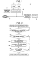
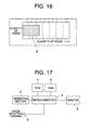
- the image adjusting apparatus 1 includes an operating section 2; microcomputer 3, ROM 4, RAM 5, image inputting terminal 6, composing/adjusting section 7, and monitor 8.
- Image data to be inputted from the image inputting terminal 6 are data from a source (not shown in the figure) such as a digital versatile disk (DVD).
- a source not shown in the figure
- DVD digital versatile disk
- the operating section 2 is an inputting device for a user to adjust an image outputted from the image adjusting apparatus 1 and includes a cursor key and decision key for use upon adjustment.
- the operating section 2 may consist of, for example, a remotecontrol which can operate the image adjusting apparatus 1.
- the microcomputer 3 as the characteristic quantity extracting device has a central processing unity (CPU) therein.
- the microcomputer 3 receives an instruction from the operating section 2, extracts the characteristic quantity from an image inputted from the image inputting terminal 6 by means of a control program stored in the ROM 4 (explained later on) so as to compose a histogram, and outputs the composed histogram to the composing/adjusting section 7.
- the microcomputer 3 Upon adjusting the image quality parameters, the microcomputer 3 outputs the instruction such as increase or decrease in values of the image quality parameters from the operating section 2 to the composing/adjusting section 7.
- the ROM 4 is a nonvolatile storage and stores a control program to be performed by the microcomputer 3.
- the RAM 5a rewritable nonvolatile storage and provisionally stores data for the microcomputer 3 to perform various processing.
- the composing/adjusting section 7 as the adjusting device and the composing device composes a display image simultaneously showing the image inputted from the image inputting terminal 6 and the histogram composed by the microcomputer 3 and outputs the composed display image to a monitor 8.
- the composing/adjusting section 7 performs the adjustments of the image quality parameters of the image inputted from the image inputting terminal 6 on the basis of an instruction from the microcomputer 3 and outputs the adjusted image to the monitor 8.
- the monitor 8 as the display device is a display device, which displays the adjusted image inputted from the composing/adjusting section 7, and includes a cathode ray tube (CRT), liquid crystal display, plasma display, rear projection display or front projection display.
- CTR cathode ray tube
- the image adjusting apparatus 1 having a structure as shown in Fig. 1, an action when a user operates the operating section 2 so as to adjust brightness as the image quality parameter of an image displayed on the monitor 8 will be explained with reference to a flow chart shown in Fig. 2.
- the flow chart shown in Fig. 2 is realized when the CPU of the microcomputer 3 performs the control program stored in the ROM 4.
- step S1 it is judges whether or not a brightness adjustment instruction is done to the microcomputer 3 with button operation or the like by a user at the operating section 2. If the instruction is done (i.e. in a case of Y), the CPU proceeds to step S2. If the instruction is not done (i.e. in a case of N), the judgment is carried out again.
- step S2 it is selected whether or not a histogram display is to be done with button operation or the like by the user at the operating section 2. If the histogram display is to be done (i.e. in a case of Y), the CPU proceeds to step S3. If the histogram display is not to be done (i.e. in a case of N), the CPU proceeds to step S4.
- the frequencies per each level of brightness of the inputted image as the characteristic quality of the inputted image are extracted with respect to the image inputted from the image inputting terminal 6 so as to compose a histogram as shown in Fig. 3, the composed histogram is outputted to the composing/adjusting section 7, and the CPU proceeds to step S4.
- the composing/adjusting section 7 composes a display image showing both of the histogram inputted from the microcomputer 3 and the image inputted from the image inputting terminal 6 as shown in Fig. 4 and outputs the composed display image to the monitor 8, which displays the composed display image.
- the histogram is a graph, wherein the frequencies per each level of brightness within the image (i.e. one frame in this EXAMPLE 1) are shown, having a level of brightness of the inputted image as its horizontal axis and frequency per each level as its longitudinal axis. That is, the histogram is data indicating the characteristic quantity, i.e. the frequency, which are obtained by composing respective levels of the brightness extracted per each of three primary colors RGB (red, green and blue) of light from the inputted image.
- RGB red, green and blue
- the level of the brightness means light and shade of the image, wherein a large level indicates a bright part while a small level indicates a dark part. Therefore, by using the histogram of the brightness, a character of the image can be shown, for example, an image including many components having large levels is a bright image, while an image including many components having small levels is a dark image.
- An indication of the histogram may be bar graphs each separate from one another per each level instead of the indication thereof as shown in Fig. 3, in which tip ends of the frequencies of the respective levels are connected to one another.
- step S4 the adjustment of the brightness is performed and the CPU proceeds to step S5.
- a user operates, for example, an on-screen display (OSD) displayed on a screen at the operating section 2 so as to perform the adjustment of the brightness.
- OSD on-screen display
- the user can perform the adjustment not only by seeing a change in the inputted image but also by confirming a change in the histogram displayed simultaneously on the screen. For example, by adjusting in such a manner that the frequencies larger than that of an A-level in Fig. 3 are increased, it is possible to adjust so as to enlarge a dynamic range of the brightness.
- step S5 it is judged whether or not an instruction to finish the adjustment is done from the operating section 2. If the instruction is done (i.e. in a case of Y), the adjustment of the brightness is finished. If the instruction is not done (i.e. in a case of N), the CPU returns to step S4.
- a histogram is composed from levels of the brightness extracted from the image to be adjusted and the adjustment is carried out with reference to both of the image and the histogram, so that the adjustment on the basis of the histogram that indicates an objective characteristic quantity of the image can be performed, that is, highly precise adjustment including, for example, an enlargement of the dynamic range is possible.
- adjusting the brightness besides simply making lighter or making darker, it is possible to adjust in more detail per each level corresponding to the histogram, that is, very fine adjustment can be realized.
- the histogram of the brightness is explained.
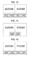
- a plurality of histograms as shown in Fig. 5 may be displayed.
- the inputted image and the histogram are displayed on a screen by dividing the screen into two parts (i.e. picture-side-picture display).
- the histogram may be displayed by superimposing the histogram on the inputted image (i.e. picture-in-picture display).
- the histogram may be displayed by superimposing the histogram on the inputted image in a permeable manner (i.e. alpha-blend display).
- the position of displaying the histogram may not be limited at right end of the screen, that is, the position of displaying the histogram may be at left end, upper end or lower end.
- EXAMPLE 2 A construction and flow chart of this EXAMPLE 2 are similar to those of EXAMPLE 1.
- EXAMPLE 1 as shown in Fig. 4, only one inputted image is displayed, then the image quality is changed in response to an adjustment action, that is, an image after the adjustment is displayed.
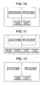
- this EXAMPLE 2 as shown in Fig. 10, an image before an adjustment and an image after the adjustment are simultaneously displayed and further, a histogram before the adjustment and a histogram after the adjustment are also displayed simultaneously.
- an image quality adjusting instruction is done at step S 1 in a flow chart shown in Fig. 2, a screen is divided into two parts at the composing/adjusting section 7. At that time, the same image is displayed on the respective divided two screens. Then, when a histogram display instruction is done at step S2, histograms are displayed on the respective two screens as shown in Fig. 10 at step S3. Then, an adjustment of an image quality parameter (brightness) is performed at step S4.
- the inputted image after the adjustment and the histogram after the adjustment are changed in response to the adjustment.
- the inputted image before the adjustment and the histogram before the adjustment do not reflect the adjustment, that is, they are not changed in response to the adjustment. Therefore, a user can carry out an adjustment seeing both of those before and after the adjustment.
- EXAMPLE 2 when the brightness is to be adjusted, a histogram of an image to be adjusted is composed, then the image and histogram before the adjustment and the image and histogram after the adjustment are displayed and then, the adjustment is performed, so that detailed adjustments can be easily carried out because one can easily recognize that how the image is changed when the histogram is changed how.
- a plurality of histograms may be displayed.
- the histogram may be displayed by superimposing the histogram on the inputted image (i.e. picture-in-picture display).
- the histogram may be displayed by superimposing the histogram on the inputted image in a permeable manner (i.e. alpha-blend display).
- the position of displaying the histogram may not be limited at right end of the screen, that is, the position of displaying the histogram may be at left end, upper end or lower end.
- an image quality parameter for composing a histogram is not limited to brightness. Instead, the image quality may be composed from respective components of three primary colors RGB (red, green and blue) of light or from a spatial frequency characteristic of an inputted image.
- RGB red, green and blue
- EXAMPLE 3 A construction of this EXAMPLE 3 is similar to that of EXAMPLES 1 and 2.
- EXAMPLES 1 and 2 the histograms per brightness level are extracted as the characteristic quantity of an inputted image and are displayed on the monitor 8.
- a graph extracting quantity of noise of an image as shown in Fig. 16 is composed and displayed on the monitor 8. Therefore, a flow chart shown in Fig. 2 remains unchanged except a point that the histogram described in the flow chart must be replaced by a bar graph.
- the noise is mixed-into or generated when an image is recorded, regenerated, coded or decoded, and the noise badly affects on image quality of an image since pixels fluctuate at random resulting in that values of the pixels are changed from their original values.
- a quantity of noise is indicated by a bar B, wherein the horizontal axis is the quantity of noise.
- the quantity of noise of horizontal axis shows the number of the pixels that are judged to be noise.
- the judgment of noise is carried out on the basis of comparison of the same pixels between the frames or comparison with neighbor pixels within the frame. Then, on the basis of the bar graph thus displayed, for example, an adjustment of intensity of noise-reduction is performed.
- EXAMPLES 1 and 2 in this EXAMPLE 3 the position of the bar graph B in Fig.
- 16 may be displayed in a form of picture-side-picture, picture-in-picture or alpha-blend, and the position of the display may be at right end, left end, upper end or lower end. Further, similarly to EXAMPLE 2, two graphs of before adjustment and after adjustment may be displayed.
- a bar graph is composed from quantity of noise extracted from the image to be adjusted and the adjustment, for example, of intensity of noise reduction is carried out with reference to both of the image and the bar graph, so that the adjustment on the basis of the bar graph that indicates an objective characteristic quantity of the image can be performed, that is, highly precise adjustment is possible.
- a histogram or a bar graph is used as the data that indicate the characteristic quantity of an inputted image.
- the data may be any data provided that the data are processed so as to objectively indicate a specific characteristic quantity which is extracted from the image.
- the microcomputer 3 extracts a histogram, the composing/adjusting section 7 composes a display image, and the monitor 8 displays the display image.
- a control program to be performed in the microcomputer 3 may carry out the function of the composing/adjusting section 7.
- the present invention can be put into practice by a software in the microcomputer 3.
- the data indicating the characteristic quantity of the image such as a histogram is erased.
- the data may be kept being displayed after finishing the adjustment. Thereby, various characteristic quantity can be always displayed.
- An image adjusting apparatus can be applied to equipment that can adjust image quality of an image such as a television set, DVD player/recorder, DVD recording/playback device, DVD recording/playback device with HDD (hard disk drive) or VCR (video cassette recorder).
- equipment that can adjust image quality of an image such as a television set, DVD player/recorder, DVD recording/playback device, DVD recording/playback device with HDD (hard disk drive) or VCR (video cassette recorder).
- An image adjusting apparatus 1 including: an composing/adjusting section 7 adjusting brightness for an inputted image; a microcomputer 3 extracting a histogram corresponding to brightness to be adjusted by the composing/adjusting section 7 from the inputted image; the composing/adjusting section 7 composing a display image simultaneously showing the histogram extracted by the microcomputer 3 and the inputted image; and a monitor 8 displaying the display image composed by the composing/adjusting section 7.
- the image adjusting apparatus 1 since the image can be adjusted on the basis of the simultaneously displayed histogram, therefore detailed and highly precise adjustments can be carried out on the basis of the histogram in comparison with a case in which the adjustment are carried out only on the basis of the image.
- An image adjusting method in which brightness are adjusted for an inputted image, including the steps of: extracting a histogram corresponding to brightness to be adjusted from the inputted image; composing a display image simultaneously showing the extracted histogram and the inputted image; and displaying the composed display image.
Landscapes
- Engineering & Computer Science (AREA)
- Multimedia (AREA)
- Signal Processing (AREA)
- Business, Economics & Management (AREA)
- Marketing (AREA)
- Human Computer Interaction (AREA)
- Controls And Circuits For Display Device (AREA)
- Facsimile Image Signal Circuits (AREA)
- Image Processing (AREA)
- Picture Signal Circuits (AREA)
- Transforming Electric Information Into Light Information (AREA)
Applications Claiming Priority (1)
| Application Number | Priority Date | Filing Date | Title |
|---|---|---|---|
| JP2006114140A JP2007288555A (ja) | 2006-04-18 | 2006-04-18 | 画像調整装置および画像調整方法 |
Publications (1)
| Publication Number | Publication Date |
|---|---|
| EP1848209A2 true EP1848209A2 (fr) | 2007-10-24 |
Family
ID=38328264
Family Applications (1)
| Application Number | Title | Priority Date | Filing Date |
|---|---|---|---|
| EP07007820A Withdrawn EP1848209A2 (fr) | 2006-04-18 | 2007-04-17 | Appareil et procédé pour régler l'image |
Country Status (3)
| Country | Link |
|---|---|
| US (1) | US20070242879A1 (fr) |
| EP (1) | EP1848209A2 (fr) |
| JP (1) | JP2007288555A (fr) |
Families Citing this family (13)
| Publication number | Priority date | Publication date | Assignee | Title |
|---|---|---|---|---|
| JP2010164597A (ja) * | 2009-01-13 | 2010-07-29 | Renesas Electronics Corp | ヒストグラム表示回路、及びヒストグラム表示方法 |
| JP2012010076A (ja) * | 2010-06-24 | 2012-01-12 | Sharp Corp | 高画質化装置および方法 |
| JP5968011B2 (ja) * | 2012-04-02 | 2016-08-10 | キヤノン株式会社 | 画像処理装置及びその制御方法 |
| JP5928386B2 (ja) * | 2013-03-22 | 2016-06-01 | カシオ計算機株式会社 | 表示制御装置、表示制御方法及びプログラム |
| JP6321953B2 (ja) * | 2013-12-05 | 2018-05-09 | 株式会社日立エルジーデータストレージ | レーザ投射表示装置 |
| CN103716561B (zh) * | 2013-12-27 | 2017-12-12 | 乐视致新电子科技(天津)有限公司 | 图像质量参数调节方法及系统 |
| CN104376542B (zh) * | 2014-10-25 | 2019-04-23 | 深圳市金立通信设备有限公司 | 一种图像增强方法 |
| JP6161222B1 (ja) * | 2016-03-17 | 2017-07-12 | シャープ株式会社 | 受信装置および放送システム |
| JP6980833B2 (ja) * | 2016-03-30 | 2021-12-15 | キヤノン株式会社 | 表示装置及び表示方法 |
| JP6350587B2 (ja) * | 2016-04-27 | 2018-07-04 | カシオ計算機株式会社 | 画像処理装置、画像処理方法及びプログラム |
| WO2018163628A1 (fr) * | 2017-03-07 | 2018-09-13 | ソニー株式会社 | Dispositif de traitement d'informations et procédé de traitement d'informations |
| CN109090864A (zh) * | 2018-09-05 | 2018-12-28 | 广州维纳斯家居股份有限公司 | 桌椅高度调整方法、装置、设备及存储介质 |
| JP7414564B2 (ja) | 2020-02-04 | 2024-01-16 | キヤノン株式会社 | 情報処理装置及び方法 |
Family Cites Families (9)
| Publication number | Priority date | Publication date | Assignee | Title |
|---|---|---|---|---|
| JPH0799589A (ja) * | 1993-05-21 | 1995-04-11 | Mitsubishi Electric Corp | カラー画像装置及びカラー画像調整方法 |
| US5982953A (en) * | 1994-09-02 | 1999-11-09 | Konica Corporation | Image displaying apparatus of a processed image from temporally sequential images |
| US7075506B2 (en) * | 2000-02-25 | 2006-07-11 | Texas Instruments Incorporated | Spatial-temporal multiplexing |
| JP2001268475A (ja) * | 2000-03-15 | 2001-09-28 | Sony Corp | 画質調整方法および画質調整装置 |
| JP4783985B2 (ja) * | 2001-02-28 | 2011-09-28 | 日本電気株式会社 | 映像処理装置、映像表示装置及びそれに用いる映像処理方法並びにそのプログラム |
| US6938060B2 (en) * | 2001-12-27 | 2005-08-30 | Texas Instruments Incorporated | Apparatus and method for graphically displaying a vector simultaneously along with the numerical values of its vector components |
| JP2004186927A (ja) * | 2002-12-03 | 2004-07-02 | Pioneer Electronic Corp | 画像信号処理装置 |
| US7315630B2 (en) * | 2003-06-26 | 2008-01-01 | Fotonation Vision Limited | Perfecting of digital image rendering parameters within rendering devices using face detection |
| JP2005309985A (ja) * | 2004-04-23 | 2005-11-04 | Canon Inc | 画像処理装置およびその方法 |
-
2006
- 2006-04-18 JP JP2006114140A patent/JP2007288555A/ja active Pending
-
2007
- 2007-04-17 EP EP07007820A patent/EP1848209A2/fr not_active Withdrawn
- 2007-04-18 US US11/785,488 patent/US20070242879A1/en not_active Abandoned
Also Published As
| Publication number | Publication date |
|---|---|
| JP2007288555A (ja) | 2007-11-01 |
| US20070242879A1 (en) | 2007-10-18 |
Similar Documents
| Publication | Publication Date | Title |
|---|---|---|
| EP1848209A2 (fr) | Appareil et procédé pour régler l'image | |
| JP4783985B2 (ja) | 映像処理装置、映像表示装置及びそれに用いる映像処理方法並びにそのプログラム | |
| US8310594B2 (en) | Method and system for picture-based user interface for adjusting picture display parameter settings of a display device | |
| US20070206121A1 (en) | Apparatus and method for adjusting image | |
| US7046252B2 (en) | Method and system for adaptive color and contrast for display devices | |
| KR20080007499A (ko) | 화상 표시 장치 및 화상 표시 방법 | |
| JP2007511159A (ja) | 周囲のビデオコンテンツに基づくクローズキャプション・テキストの適合 | |
| JP5335961B2 (ja) | 表示装置およびテレビ受像機 | |
| CN101141654A (zh) | 图像处理设备、显示设备和图像处理方法 | |
| US20070242898A1 (en) | Image processing apparatus, image processing method, and image processing program | |
| WO2017159182A1 (fr) | Dispositif de commande d'affichage, appareil d'affichage, récepteur de télévision, procédé de commande de dispositif de commande d'affichage, programme de commande et support d'enregistrement | |
| CN101119452A (zh) | 视频处理装置及其信息显示方法 | |
| JP2015125346A (ja) | 表示装置、制御装置及び制御方法 | |
| JP2008507162A (ja) | ビデオ表示装置における黒色非アクティブ領域の調和的除去 | |
| KR100439726B1 (ko) | 디스플레이장치 및 디스플레이장치의 휘도조정방법 | |
| KR100595442B1 (ko) | 디스플레이 장치 | |
| JP4412956B2 (ja) | 映像表示装置 | |
| JP2008193645A (ja) | 明るさ補正装置、その方法、および、表示装置 | |
| JP2006078693A (ja) | 画像表示装置 | |
| JP4886992B2 (ja) | 画像処理装置、表示装置、画像処理方法及びプログラム | |
| KR100774008B1 (ko) | 디스플레이장치 및 그 제어방법 | |
| JP5189810B2 (ja) | 画質制御装置及び画質制御方法 | |
| KR100702239B1 (ko) | 디스플레이장치 및 그 화질설정방법 | |
| KR101100159B1 (ko) | 영상 표시 기기의 이중 화면 휘도 자동 조정 장치 및 방법 | |
| JP4948999B2 (ja) | 調整パラメータの設定方法及び表示装置 |
Legal Events
| Date | Code | Title | Description |
|---|---|---|---|
| PUAI | Public reference made under article 153(3) epc to a published international application that has entered the european phase |
Free format text: ORIGINAL CODE: 0009012 |
|
| AK | Designated contracting states |
Kind code of ref document: A2 Designated state(s): AT BE BG CH CY CZ DE DK EE ES FI FR GB GR HU IE IS IT LI LT LU LV MC MT NL PL PT RO SE SI SK TR |
|
| AX | Request for extension of the european patent |
Extension state: AL BA HR MK YU |
|
| RAP1 | Party data changed (applicant data changed or rights of an application transferred) |
Owner name: PIONEER CORPORATION |
|
| STAA | Information on the status of an ep patent application or granted ep patent |
Free format text: STATUS: THE APPLICATION IS DEEMED TO BE WITHDRAWN |
|
| 18D | Application deemed to be withdrawn |
Effective date: 20101102 |