EP1848878B1 - Basculeur commutable d'un mecanisme de distribution d'un moteur a combustion interne - Google Patents
Basculeur commutable d'un mecanisme de distribution d'un moteur a combustion interne Download PDFInfo
- Publication number
- EP1848878B1 EP1848878B1 EP06706392.5A EP06706392A EP1848878B1 EP 1848878 B1 EP1848878 B1 EP 1848878B1 EP 06706392 A EP06706392 A EP 06706392A EP 1848878 B1 EP1848878 B1 EP 1848878B1
- Authority
- EP
- European Patent Office
- Prior art keywords
- lever
- piston
- rocker arm
- coupling
- driving surface
- Prior art date
- Legal status (The legal status is an assumption and is not a legal conclusion. Google has not performed a legal analysis and makes no representation as to the accuracy of the status listed.)
- Expired - Lifetime
Links
Images

Classifications
-
- F—MECHANICAL ENGINEERING; LIGHTING; HEATING; WEAPONS; BLASTING
- F01—MACHINES OR ENGINES IN GENERAL; ENGINE PLANTS IN GENERAL; STEAM ENGINES
- F01L—CYCLICALLY OPERATING VALVES FOR MACHINES OR ENGINES
- F01L1/00—Valve-gear or valve arrangements, e.g. lift-valve gear
- F01L1/12—Transmitting gear between valve drive and valve
- F01L1/18—Rocking arms or levers
- F01L1/185—Overhead end-pivot rocking arms
-
- F—MECHANICAL ENGINEERING; LIGHTING; HEATING; WEAPONS; BLASTING
- F01—MACHINES OR ENGINES IN GENERAL; ENGINE PLANTS IN GENERAL; STEAM ENGINES
- F01L—CYCLICALLY OPERATING VALVES FOR MACHINES OR ENGINES
- F01L1/00—Valve-gear or valve arrangements, e.g. lift-valve gear
- F01L1/12—Transmitting gear between valve drive and valve
- F01L1/18—Rocking arms or levers
- F01L2001/186—Split rocking arms, e.g. rocker arms having two articulated parts and means for varying the relative position of these parts or for selectively connecting the parts to move in unison
-
- Y—GENERAL TAGGING OF NEW TECHNOLOGICAL DEVELOPMENTS; GENERAL TAGGING OF CROSS-SECTIONAL TECHNOLOGIES SPANNING OVER SEVERAL SECTIONS OF THE IPC; TECHNICAL SUBJECTS COVERED BY FORMER USPC CROSS-REFERENCE ART COLLECTIONS [XRACs] AND DIGESTS
- Y10—TECHNICAL SUBJECTS COVERED BY FORMER USPC
- Y10T—TECHNICAL SUBJECTS COVERED BY FORMER US CLASSIFICATION
- Y10T74/00—Machine element or mechanism
- Y10T74/21—Elements
- Y10T74/2101—Cams
- Y10T74/2107—Follower
Definitions
- the invention relates to a rocker arm of a valve train of an internal combustion engine, which is switchable to different strokes for at least one gas exchange valve, with an outer and between its arms extending and pivotable relative to this inner lever, wherein at one end of the lever extending in a lever longitudinal direction Drill hole is applied with a piston, which piston is partially slidable with its top under a driver surface of one end of the other lever, so that in this coupling a large and decoupling a small or 0-valve stroke is generated, wherein at an underside of the finger lever at one end a system for a gas exchange valve and the other end a complementary surface for a support element is applied and wherein at least the decoupling in the decoupling lever on its upper side is acted upon by at least one cognitivehubnocken.
- a generic rocker arm goes out of the DE 103 18 295 A1 out. Its piston as a coupling means extends in a bore at one end of the inner member and can for the coupling case sections under a corresponding complementarily shaped driving surface of a crossbar of the outer lever are displaced.
- document EP 1 408 203 discloses a similar valve train.
- the object of the invention is therefore to provide a switchable drag lever of the aforementioned type, in which the disadvantageous "edge support" are eliminated by simple means.
- this object is achieved in that the piston is provided in its coupling region, as well as starting from its lying in the coupling direction, either with a rising, radii-like profiling or with a sloping, radii profiling, the driver surface of the other lever follows the profiling cone-like and wherein in coupling a contact point of the piston is located on the driving surface in the region of half the depth of the driving surface.
- this object is solved by the features of the independent claim 2, according to which the piston is shown smooth cylindrical, wherein at coupling whose contact point on the driver surface is in the region of half the depth of the driver surface and wherein the driver surface, starting from the contact point, on both sides with a sloping Radial profiling is provided.
- a contact point of the piston on the driver surface should lie approximately in the region of half the depth of the driver surface.
- the aforementioned contact point is at least not to be found in the region of the edges of the complementary surface at their ends.
- the proposed radius profiling on the piston can be generated for example by sliding or belt grinding.
- driver surface is the subject of another subclaim. Accordingly, it should be represented, for example, as an indentation on an underside of a crossbeam of the respective other lever, for example the outer lever. However, it is also conceivable and intended to represent the driver surface as part of a bore of a crossbar of the other lever.
- the bore with the piston in the inner lever above a formed, for example, as a dome-shaped indentation complementary surface for the support element, to arrange and thus displace the piston for its coupling case longitudinally outward under the corresponding cam surface.
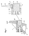
- FIG. 1 discloses a switchable rocker arm 1, as he from its basic structure in the aforementioned DE 103 18 295 A1 is described. As a further reference is at this point the US 5,544,626 called, but in which the piston extends in a bore of the outer lever.
- the drag lever 1 consists of an outer lever 2, between the arms, not shown, which is shown here only in the region of its one end 4 inner lever 3 is added.
- the arms of the outer lever 2 are in the range its one end 8 connected by a crossbar 17. It can also be seen that in the region of the end 4 of the inner lever 3, on the underside 9, a dome-shaped complementary surface 11 is applied. This serves to support the inner and thus the entire drag lever 3, 1 on a head of a support member not shown in the drawing.
- the coupling region of the piston 6 is shown pulled out enlarged.
- a smooth cylindrical piston 6 is present.
- the condition at coupling can be recognized.
- the driving surface 7, starting from the contact point K, on both sides with a sloping, radii-like profiling 15 is provided.
- the contact point K is approximately in the range of half a depth or here at half the thickness of the crossbar 17 of the driver surface 7. Due to this profiling according to the invention is no longer in coupling to the aforementioned, adverse "edge beams".
- the piston 6 has in its coupling region a sloping radii profiling 14. This starts from its lying in the coupling direction of the forehead 12.
- the region B P of the profiling is at least pulled over the coupling portion of the piston 6.
- “R” stands in all figures for the radius of Profili e-tion and "M” for its center, which of course can be elsewhere.
- the driver surface 7 follows the profiling 14 approximately cone-like.
- the contact point K is in this case again in the region of half the depth of the driver surface 7.
- FIG. 2 different profiling shows FIG. 3 , Accordingly, the piston 6 has on its outer shell, starting from its outer end 12, an increasing, radii-like profiling 13. This in turn is the cone-like following cam surface 7 opposite.
- the term "half depth" is related to the insertion region of the piston 6 when coupled.
Landscapes
- Engineering & Computer Science (AREA)
- Mechanical Engineering (AREA)
- General Engineering & Computer Science (AREA)
- Valve-Gear Or Valve Arrangements (AREA)
- Actuator (AREA)
- Valve Device For Special Equipments (AREA)
Claims (5)
- Culbuteur (1) d'un mécanisme de distribution d'un moteur à combustion interne, qui peut être commuté sur différentes levées pour au moins une soupape d'échange de gaz, comprenant un levier extérieur et un levier intérieur (2, 3) s'étendant entre les bras de celui-ci et pivotant par rapport à celui-ci, un alésage (5) s'étendant dans la direction longitudinale du levier et comprenant un piston (6) étant réalisé à une extrémité (4) de l'un des leviers (3 ou 2), lequel piston (6) pouvant être poussé par sa face supérieure en partie en dessous d'une surface d'entraînement (7) d'une extrémité (8) de l'autre levier respectif (2, 3), de sorte que, lors de cet accouplement, une plus grande levée de soupape soit produite et que, lors d'un désaccouplement, une plus petite levée de soupape ou une levée de soupape nulle soit produite et, sur une face inférieure (9) du culbuteur (1), un appui pour une soupape d'échange de gaz étant réalisé à une extrémité et une surface complémentaire (11) pour un élément de support étant réalisée à l'autre extrémité, et au moins le levier (2, 3) pivotant vers le bas en cas de désaccouplement pouvant être sollicité sur sa face supérieure par au moins une came à grande levée, caractérisé en ce que le piston (6), dans sa région d'accouplement ainsi qu'à partir de sa face frontale (12) située dans la direction d'accouplement, est pourvu soit d'un profilage (13) radial montant soit d'un profilage (14) radial descendant, la surface d'entraînement (7) de l'autre levier (2, 3) suivant le profilage (13, 14) à la manière d'un cône et, lors de l'accouplement, un point de contact (K) du piston (6) sur la surface d'entraînement (7) se situant dans la région de la moitié de la profondeur de la surface d'entraînement (7).
- Culbuteur selon le préambule de la revendication 1, le piston (6) étant représenté de manière cylindrique lisse, caractérisé en ce que, lors de l'accouplement, son point de contact (K) se situe sur la surface d'entraînement (7) dans la région de la moitié de la profondeur de la surface d'entraînement (7) et la surface d'entraînement (7), à partir du point de contact (K), étant pourvue des deux côtés d'un profilage (15) radial descendant.
- Culbuteur selon la revendication 1 ou 2, caractérisé en ce que la surface d'entraînement (7) est présente soit en tant qu'évidement sur une face inférieure (16) d'une traverse (17) soit en tant qu'élément constitutif d'un alésage d'une traverse (17) à l'extrémité (8) de l'autre levier (2, 3) respectif.
- Culbuteur selon l'une quelconque des revendications précédentes, caractérisé en ce que le levier intérieur (3) est pourvu de l'appui pour la soupape d'échange de gaz et de la surface complémentaire (11) pour l'élément de support, l'alésage (5) comprenant le piston (6) s'étendant au-dessus de la surface complémentaire (11) pour l'élément de support dans le levier intérieur (3) ou s'étendant latéralement par rapport à cette surface complémentaire.
- Culbuteur selon la revendication 4, caractérisé en ce que l'alésage (5) pour le piston (6) est réalisé, en tant qu'alésage débouchant, dans le levier intérieur (3).
Applications Claiming Priority (2)
| Application Number | Priority Date | Filing Date | Title |
|---|---|---|---|
| DE102005006954A DE102005006954A1 (de) | 2005-02-16 | 2005-02-16 | Schaltbarer Schlepphebel eines Ventiltriebs einer Brennkraftmaschine |
| PCT/EP2006/000621 WO2006087076A1 (fr) | 2005-02-16 | 2006-01-25 | Basculeur commutable d'un mecanisme de distribution d'un moteur a combustion interne |
Publications (2)
| Publication Number | Publication Date |
|---|---|
| EP1848878A1 EP1848878A1 (fr) | 2007-10-31 |
| EP1848878B1 true EP1848878B1 (fr) | 2013-04-17 |
Family
ID=36096346
Family Applications (1)
| Application Number | Title | Priority Date | Filing Date |
|---|---|---|---|
| EP06706392.5A Expired - Lifetime EP1848878B1 (fr) | 2005-02-16 | 2006-01-25 | Basculeur commutable d'un mecanisme de distribution d'un moteur a combustion interne |
Country Status (4)
| Country | Link |
|---|---|
| US (1) | US7503300B2 (fr) |
| EP (1) | EP1848878B1 (fr) |
| DE (1) | DE102005006954A1 (fr) |
| WO (1) | WO2006087076A1 (fr) |
Families Citing this family (5)
| Publication number | Priority date | Publication date | Assignee | Title |
|---|---|---|---|---|
| USD833482S1 (en) | 2015-07-13 | 2018-11-13 | Eaton Corporation | Rocker arm |
| USD791190S1 (en) | 2015-07-13 | 2017-07-04 | Eaton Corporation | Rocker arm assembly |
| USD830414S1 (en) | 2015-12-10 | 2018-10-09 | Eaton S.R.L. | Roller rocker arm of an engine |
| US10753237B2 (en) * | 2018-05-29 | 2020-08-25 | Schaeffler Technologies AG & Co. KG | Actuation arrangement for switchable lever |
| DE102022116589A1 (de) * | 2022-07-04 | 2024-01-04 | Schaeffler Technologies AG & Co. KG | Anordnung zum Koppeln von beweglich zueinander angeordneten Bauteilen für eine schaltbare Ventiltriebkomponente einer Brennkraftmaschine |
Family Cites Families (7)
| Publication number | Priority date | Publication date | Assignee | Title |
|---|---|---|---|---|
| US5544626A (en) * | 1995-03-09 | 1996-08-13 | Ford Motor Company | Finger follower rocker arm with engine valve deactivator |
| DE19630309C2 (de) * | 1996-07-06 | 2001-10-11 | Meta Motoren Energietech | Vorrichtung zum Unterbrechen des Kraftflusses zwischen einer Nockenwelle und mindestens einem Ventil |
| DE10038917A1 (de) * | 2000-08-09 | 2002-02-21 | Fev Motorentech Gmbh | Kolbenbrennkraftmaschine mit deaktivierbaren, mechanisch betätigbaren Gaswechselventilen |
| US6805083B2 (en) * | 2002-10-10 | 2004-10-19 | Ford Global Technologies, Llc | Cam cover gasket |
| DE10310220A1 (de) * | 2003-03-08 | 2004-09-16 | Daimlerchrysler Ag | Vorrichtung zur Koppelung bzw. Entkoppelung zweier Betätigungshebel eines Ventiltriebes einer Brennkraftmaschine und Verfahren hierzu |
| DE102004007766A1 (de) * | 2003-03-20 | 2004-09-30 | Ina-Schaeffler Kg | Schlepphebel eines Ventiltriebs einer Brennkraftmaschine |
| DE10318295A1 (de) * | 2003-04-23 | 2004-11-11 | Ina-Schaeffler Kg | Schlepphebel eines Ventiltriebs einer Brennkraftmaschine |
-
2005
- 2005-02-16 DE DE102005006954A patent/DE102005006954A1/de not_active Withdrawn
-
2006
- 2006-01-25 EP EP06706392.5A patent/EP1848878B1/fr not_active Expired - Lifetime
- 2006-01-25 WO PCT/EP2006/000621 patent/WO2006087076A1/fr not_active Ceased
- 2006-01-25 US US11/816,466 patent/US7503300B2/en not_active Expired - Fee Related
Also Published As
| Publication number | Publication date |
|---|---|
| DE102005006954A1 (de) | 2006-08-17 |
| WO2006087076A1 (fr) | 2006-08-24 |
| EP1848878A1 (fr) | 2007-10-31 |
| US7503300B2 (en) | 2009-03-17 |
| US20080264368A1 (en) | 2008-10-30 |
Similar Documents
| Publication | Publication Date | Title |
|---|---|---|
| EP1616082B1 (fr) | Basculeur d'un mecanisme de distribution d'un moteur a combustion interne | |
| EP1785595B1 (fr) | Culbuteur commutable d'un mécanisme de distribution d'un moteur à combustion interne | |
| EP2013450B1 (fr) | Basculeur commutable d'un mécanisme de distribution d'un moteur à combustion interne | |
| EP2226477B1 (fr) | Unité hydraulique pour culasse de moteur à combustion interne dotée d'une commande hydraulique variable de soupape | |
| DE102005037052A1 (de) | Schaltbarer Schlepphebel eines Ventiltriebs einer Brennkraftmaschine | |
| DE102008063336A1 (de) | System zur Erzielung eines kontinuierlich variablen Ventilhubs an einem Motor | |
| DE102008030794A1 (de) | Koppeleinrichtung eines schaltbaren Schlepphebels eines Ventiltriebs einer Brennkraftmaschine | |
| DE102007011892A1 (de) | Schaltbares Abstützelement für einen Ventiltrieb einer Brennkraftmaschine | |
| DE10310226A1 (de) | Schlepphebel eines Ventiltriebs einer Brennkraftmaschine | |
| EP1881165A2 (fr) | Commande de soupape embrayable pour un moteur à combustion interne | |
| EP1848878B1 (fr) | Basculeur commutable d'un mecanisme de distribution d'un moteur a combustion interne | |
| DE102007031810A1 (de) | Schaltbarer Ventiltrieb für eine Brennkraftmaschine | |
| DE102006007489B4 (de) | Verriegelungsanordnung für eine Ventilabschaltungseinrichtung | |
| WO2008043717A2 (fr) | Levier oscillant | |
| DE102007011893A1 (de) | Schaltbares Abstützelement für einen Ventiltrieb einer Brennkraftmaschine | |
| EP1260679A2 (fr) | Poussoir de moteur à combustion interne | |
| DE102019133517A1 (de) | Ventilbrücke für den Ventiltrieb einer Brennkraftmaschine | |
| EP1357257A2 (fr) | Culbuteur en tole | |
| EP2142767B9 (fr) | poussoir de soupape commutable | |
| EP2295739A1 (fr) | Commande de soupape d'un moteur à combustion interne | |
| DE102007008409A1 (de) | Ventiltrieb einer Brennkraftmaschine mit einem Schlepphebel | |
| DE102019120910A1 (de) | Kipphebel für einen Ventiltrieb einer Nutzfahrzeug-Brennkraftmaschine | |
| DE19930574A1 (de) | Ventiltrieb einer Brennkraftmaschine | |
| DE102019107640A1 (de) | Nockenstösselanordnung | |
| DE102012218661A1 (de) | Hebelartiger Nockenfolger |
Legal Events
| Date | Code | Title | Description |
|---|---|---|---|
| PUAI | Public reference made under article 153(3) epc to a published international application that has entered the european phase |
Free format text: ORIGINAL CODE: 0009012 |
|
| 17P | Request for examination filed |
Effective date: 20070730 |
|
| AK | Designated contracting states |
Kind code of ref document: A1 Designated state(s): DE FR GB IT SE |
|
| DAX | Request for extension of the european patent (deleted) | ||
| RBV | Designated contracting states (corrected) |
Designated state(s): DE FR GB IT SE |
|
| RAP1 | Party data changed (applicant data changed or rights of an application transferred) |
Owner name: SCHAEFFLER TECHNOLOGIES AG & CO. KG |
|
| GRAP | Despatch of communication of intention to grant a patent |
Free format text: ORIGINAL CODE: EPIDOSNIGR1 |
|
| GRAS | Grant fee paid |
Free format text: ORIGINAL CODE: EPIDOSNIGR3 |
|
| GRAA | (expected) grant |
Free format text: ORIGINAL CODE: 0009210 |
|
| AK | Designated contracting states |
Kind code of ref document: B1 Designated state(s): DE FR GB IT SE |
|
| REG | Reference to a national code |
Ref country code: GB Ref legal event code: FG4D Free format text: NOT ENGLISH |
|
| REG | Reference to a national code |
Ref country code: DE Ref legal event code: R096 Ref document number: 502006012739 Country of ref document: DE Effective date: 20130613 |
|
| PG25 | Lapsed in a contracting state [announced via postgrant information from national office to epo] |
Ref country code: SE Free format text: LAPSE BECAUSE OF FAILURE TO SUBMIT A TRANSLATION OF THE DESCRIPTION OR TO PAY THE FEE WITHIN THE PRESCRIBED TIME-LIMIT Effective date: 20130417 |
|
| REG | Reference to a national code |
Ref country code: DE Ref legal event code: R097 Ref document number: 502006012739 Country of ref document: DE |
|
| PLBE | No opposition filed within time limit |
Free format text: ORIGINAL CODE: 0009261 |
|
| STAA | Information on the status of an ep patent application or granted ep patent |
Free format text: STATUS: NO OPPOSITION FILED WITHIN TIME LIMIT |
|
| PG25 | Lapsed in a contracting state [announced via postgrant information from national office to epo] |
Ref country code: IT Free format text: LAPSE BECAUSE OF FAILURE TO SUBMIT A TRANSLATION OF THE DESCRIPTION OR TO PAY THE FEE WITHIN THE PRESCRIBED TIME-LIMIT Effective date: 20130417 |
|
| RAP2 | Party data changed (patent owner data changed or rights of a patent transferred) |
Owner name: SCHAEFFLER TECHNOLOGIES GMBH & CO. KG |
|
| 26N | No opposition filed |
Effective date: 20140120 |
|
| REG | Reference to a national code |
Ref country code: DE Ref legal event code: R081 Ref document number: 502006012739 Country of ref document: DE Owner name: SCHAEFFLER TECHNOLOGIES GMBH & CO. KG, DE Free format text: FORMER OWNER: SCHAEFFLER TECHNOLOGIES AG & CO. KG, 91074 HERZOGENAURACH, DE Effective date: 20140218 Ref country code: DE Ref legal event code: R081 Ref document number: 502006012739 Country of ref document: DE Owner name: SCHAEFFLER TECHNOLOGIES AG & CO. KG, DE Free format text: FORMER OWNER: SCHAEFFLER TECHNOLOGIES AG & CO. KG, 91074 HERZOGENAURACH, DE Effective date: 20140218 Ref country code: DE Ref legal event code: R081 Ref document number: 502006012739 Country of ref document: DE Owner name: SCHAEFFLER TECHNOLOGIES AG & CO. KG, DE Free format text: FORMER OWNER: SCHAEFFLER KG, 91074 HERZOGENAURACH, DE Effective date: 20130418 Ref country code: DE Ref legal event code: R081 Ref document number: 502006012739 Country of ref document: DE Owner name: SCHAEFFLER TECHNOLOGIES GMBH & CO. KG, DE Free format text: FORMER OWNER: SCHAEFFLER KG, 91074 HERZOGENAURACH, DE Effective date: 20130418 |
|
| REG | Reference to a national code |
Ref country code: DE Ref legal event code: R097 Ref document number: 502006012739 Country of ref document: DE Effective date: 20140120 |
|
| REG | Reference to a national code |
Ref country code: DE Ref legal event code: R081 Ref document number: 502006012739 Country of ref document: DE Owner name: SCHAEFFLER TECHNOLOGIES AG & CO. KG, DE Free format text: FORMER OWNER: SCHAEFFLER TECHNOLOGIES GMBH & CO. KG, 91074 HERZOGENAURACH, DE Effective date: 20150223 |
|
| REG | Reference to a national code |
Ref country code: FR Ref legal event code: PLFP Year of fee payment: 11 |
|
| REG | Reference to a national code |
Ref country code: FR Ref legal event code: PLFP Year of fee payment: 12 |
|
| PGFP | Annual fee paid to national office [announced via postgrant information from national office to epo] |
Ref country code: FR Payment date: 20170126 Year of fee payment: 12 |
|
| PGFP | Annual fee paid to national office [announced via postgrant information from national office to epo] |
Ref country code: GB Payment date: 20170131 Year of fee payment: 12 |
|
| PGFP | Annual fee paid to national office [announced via postgrant information from national office to epo] |
Ref country code: DE Payment date: 20180329 Year of fee payment: 13 |
|
| GBPC | Gb: european patent ceased through non-payment of renewal fee |
Effective date: 20180125 |
|
| PG25 | Lapsed in a contracting state [announced via postgrant information from national office to epo] |
Ref country code: FR Free format text: LAPSE BECAUSE OF NON-PAYMENT OF DUE FEES Effective date: 20180131 |
|
| REG | Reference to a national code |
Ref country code: FR Ref legal event code: ST Effective date: 20180928 |
|
| PG25 | Lapsed in a contracting state [announced via postgrant information from national office to epo] |
Ref country code: GB Free format text: LAPSE BECAUSE OF NON-PAYMENT OF DUE FEES Effective date: 20180125 |
|
| REG | Reference to a national code |
Ref country code: DE Ref legal event code: R119 Ref document number: 502006012739 Country of ref document: DE |
|
| PG25 | Lapsed in a contracting state [announced via postgrant information from national office to epo] |
Ref country code: DE Free format text: LAPSE BECAUSE OF NON-PAYMENT OF DUE FEES Effective date: 20190801 |
|
| P01 | Opt-out of the competence of the unified patent court (upc) registered |
Effective date: 20230522 |