EP1849512A1 - Zusätzliches Staubsammelsystem - Google Patents
Zusätzliches Staubsammelsystem Download PDFInfo
- Publication number
- EP1849512A1 EP1849512A1 EP07251602A EP07251602A EP1849512A1 EP 1849512 A1 EP1849512 A1 EP 1849512A1 EP 07251602 A EP07251602 A EP 07251602A EP 07251602 A EP07251602 A EP 07251602A EP 1849512 A1 EP1849512 A1 EP 1849512A1
- Authority
- EP
- European Patent Office
- Prior art keywords
- dust
- dust collection
- arrangement according
- drum
- collection arrangement
- Prior art date
- Legal status (The legal status is an assumption and is not a legal conclusion. Google has not performed a legal analysis and makes no representation as to the accuracy of the status listed.)
- Withdrawn
Links
- 239000000428 dust Substances 0.000 title claims abstract description 169
- 210000002445 nipple Anatomy 0.000 claims description 6
- 230000003068 static effect Effects 0.000 claims description 2
- 238000000151 deposition Methods 0.000 claims 1
- 239000002244 precipitate Substances 0.000 abstract description 4
- 230000003584 silencer Effects 0.000 description 17
- 238000000034 method Methods 0.000 description 11
- 239000006260 foam Substances 0.000 description 8
- 239000000463 material Substances 0.000 description 8
- 239000002023 wood Substances 0.000 description 6
- 238000000926 separation method Methods 0.000 description 5
- 239000010813 municipal solid waste Substances 0.000 description 4
- 238000001914 filtration Methods 0.000 description 3
- 239000004033 plastic Substances 0.000 description 3
- 229920003023 plastic Polymers 0.000 description 3
- 229910000831 Steel Inorganic materials 0.000 description 2
- 238000010276 construction Methods 0.000 description 2
- 239000006261 foam material Substances 0.000 description 2
- -1 polyethylene Polymers 0.000 description 2
- 239000007787 solid Substances 0.000 description 2
- 239000010959 steel Substances 0.000 description 2
- 239000002699 waste material Substances 0.000 description 2
- 239000004698 Polyethylene Substances 0.000 description 1
- 239000004809 Teflon Substances 0.000 description 1
- 229920006362 Teflon® Polymers 0.000 description 1
- 238000010521 absorption reaction Methods 0.000 description 1
- 239000012814 acoustic material Substances 0.000 description 1
- 238000007664 blowing Methods 0.000 description 1
- 210000000988 bone and bone Anatomy 0.000 description 1
- 239000000872 buffer Substances 0.000 description 1
- 238000004140 cleaning Methods 0.000 description 1
- 239000013536 elastomeric material Substances 0.000 description 1
- 238000000227 grinding Methods 0.000 description 1
- 231100001261 hazardous Toxicity 0.000 description 1
- 231100000206 health hazard Toxicity 0.000 description 1
- 230000006698 induction Effects 0.000 description 1
- 239000002184 metal Substances 0.000 description 1
- NJPPVKZQTLUDBO-UHFFFAOYSA-N novaluron Chemical compound C1=C(Cl)C(OC(F)(F)C(OC(F)(F)F)F)=CC=C1NC(=O)NC(=O)C1=C(F)C=CC=C1F NJPPVKZQTLUDBO-UHFFFAOYSA-N 0.000 description 1
- 239000002245 particle Substances 0.000 description 1
- 239000013618 particulate matter Substances 0.000 description 1
- 239000011505 plaster Substances 0.000 description 1
- 239000002985 plastic film Substances 0.000 description 1
- 229920006255 plastic film Polymers 0.000 description 1
- 229920000573 polyethylene Polymers 0.000 description 1
- 230000001376 precipitating effect Effects 0.000 description 1
- 238000001556 precipitation Methods 0.000 description 1
- 238000005086 pumping Methods 0.000 description 1
- 229920005989 resin Polymers 0.000 description 1
- 239000011347 resin Substances 0.000 description 1
- 230000029058 respiratory gaseous exchange Effects 0.000 description 1
- 238000009420 retrofitting Methods 0.000 description 1
- 238000001228 spectrum Methods 0.000 description 1
- 239000004575 stone Substances 0.000 description 1
- 230000001629 suppression Effects 0.000 description 1
- XLYOFNOQVPJJNP-UHFFFAOYSA-N water Substances O XLYOFNOQVPJJNP-UHFFFAOYSA-N 0.000 description 1
Images


Classifications
-
- B—PERFORMING OPERATIONS; TRANSPORTING
- B01—PHYSICAL OR CHEMICAL PROCESSES OR APPARATUS IN GENERAL
- B01D—SEPARATION
- B01D45/00—Separating dispersed particles from gases or vapours by gravity, inertia, or centrifugal forces
- B01D45/12—Separating dispersed particles from gases or vapours by gravity, inertia, or centrifugal forces by centrifugal forces
-
- B—PERFORMING OPERATIONS; TRANSPORTING
- B01—PHYSICAL OR CHEMICAL PROCESSES OR APPARATUS IN GENERAL
- B01D—SEPARATION
- B01D50/00—Combinations of methods or devices for separating particles from gases or vapours
- B01D50/20—Combinations of devices covered by groups B01D45/00 and B01D46/00
-
- B—PERFORMING OPERATIONS; TRANSPORTING
- B04—CENTRIFUGAL APPARATUS OR MACHINES FOR CARRYING-OUT PHYSICAL OR CHEMICAL PROCESSES
- B04C—APPARATUS USING FREE VORTEX FLOW, e.g. CYCLONES
- B04C5/00—Apparatus in which the axial direction of the vortex is reversed
- B04C5/14—Construction of the underflow ducting; Apex constructions; Discharge arrangements ; discharge through sidewall provided with a few slits or perforations
- B04C5/185—Dust collectors
-
- B—PERFORMING OPERATIONS; TRANSPORTING
- B08—CLEANING
- B08B—CLEANING IN GENERAL; PREVENTION OF FOULING IN GENERAL
- B08B15/00—Preventing escape of dirt or fumes from the area where they are produced; Collecting or removing dirt or fumes from that area
- B08B15/04—Preventing escape of dirt or fumes from the area where they are produced; Collecting or removing dirt or fumes from that area from a small area, e.g. a tool
-
- B—PERFORMING OPERATIONS; TRANSPORTING
- B24—GRINDING; POLISHING
- B24B—MACHINES, DEVICES, OR PROCESSES FOR GRINDING OR POLISHING; DRESSING OR CONDITIONING OF ABRADING SURFACES; FEEDING OF GRINDING, POLISHING, OR LAPPING AGENTS
- B24B55/00—Safety devices for grinding or polishing machines; Accessories fitted to grinding or polishing machines for keeping tools or parts of the machine in good working condition
- B24B55/06—Dust extraction equipment on grinding or polishing machines
-
- B—PERFORMING OPERATIONS; TRANSPORTING
- B04—CENTRIFUGAL APPARATUS OR MACHINES FOR CARRYING-OUT PHYSICAL OR CHEMICAL PROCESSES
- B04C—APPARATUS USING FREE VORTEX FLOW, e.g. CYCLONES
- B04C9/00—Combinations with other devices, e.g. fans, expansion chambers, diffusors, water locks
- B04C2009/002—Combinations with other devices, e.g. fans, expansion chambers, diffusors, water locks with external filters
-
- Y—GENERAL TAGGING OF NEW TECHNOLOGICAL DEVELOPMENTS; GENERAL TAGGING OF CROSS-SECTIONAL TECHNOLOGIES SPANNING OVER SEVERAL SECTIONS OF THE IPC; TECHNICAL SUBJECTS COVERED BY FORMER USPC CROSS-REFERENCE ART COLLECTIONS [XRACs] AND DIGESTS
- Y10—TECHNICAL SUBJECTS COVERED BY FORMER USPC
- Y10S—TECHNICAL SUBJECTS COVERED BY FORMER USPC CROSS-REFERENCE ART COLLECTIONS [XRACs] AND DIGESTS
- Y10S55/00—Gas separation
- Y10S55/18—Work bench
Definitions
- This invention is directed to devices and equipment for collecting bulk solids, for example, process dust coming from a dust generating tool, such as a sanding machine, where the dust is entrained in a flow of air from the source machine, and is separated out at the dust collection equipment where the dust precipitates into a drum, barrel, or similar container.
- the invention is more specifically directed to a compact and efficient device to be used between a tool and a vacuum source, e.g., shop vacuum, to separate and collect the dust from the airstream emerging from the tool before the air stream reaches the vacuum source.
- the invention is likewise concerned with a simple and straightforward dust separation assembly that can be associated with a tool that has a duct from with the air stream plus entrained dust particles proceed.
- the invention is also concerned with a simple and straightforward silencer device that can be dropped in to the cylindrical filter of a cyclonic dust collection system to reduce the equipment noise by 3 to 8 dB.
- some means has to be provided to dispense with the grindings, chips, and particulate matter that is generated by the machine during operation.
- wood working machines such as sanders, joiners, and the like
- wood that is removed from a workpiece has to be collected and removed from the work area so as to avoid either a breathing hazard for the workman or a fire hazard.
- sanders and buffers it is conventional to draw off the dust that is generated by the machines and then send the air that is carrying the dust into a filter bag arrangement, or to draw off the dust through a flexible hose or conduit.
- the conduit or hose extends from a dust outlet duct of the machine to a collection station.
- the stream of air is pumped through a flexible hose conduit, with the entrained process dust, to a piece of equipment that provides suction and some filtering, e.g., a shop vacuum.
- a shop vacuum This arrangement requires that the shop vacuum be cleaned and emptied regularly, to keep the wood dust from clogging the machine.
- This arrangement also does nothing to reduce the level of process noise from operation of the dust collection equipment.
- the invention provides a dust collection arrangement that can be used in line between the dust producing tool and a suction source, such as a shop vacuum cleaner, that can separate out between 95% and 99% of the dust entrained in the air stream emerging from the tool.
- a suction source such as a shop vacuum cleaner
- the invention provides an auxiliary dust collection arrangement that is simple and straightforward in construction, highly reliable, and adaptable to a wide range of tools.
- the invention provides a dust collection system which does not significantly increase the system energy draw.
- an auxiliary dust collection arrangement is interposed between a dust producing tool, such as an electric sander or other woodworking tool, and a vacuum apparatus, e.g., a shop vacuum cleaner, for intercepting and removing dust carried in an air stream from the tool to the vacuum apparatus.
- the dust collection arrangement has a first flexible hose that extends from a discharge duct on the tool to an inlet pipe of a cyclonic separator.
- This separator has a generally conic body, i.e., which is wider at the top and narrowing to a nose or apex at its lower end.
- a vortex tube extends upward from the interior of the conic body, and its upper end can constitute an air outlet pipe, which extends from the top of the conic body.
- the process dust in the air stream separates in the body and proceeds to the nose of the conic body, and the main air stream leaves via the air outlet pipe.
- This drum should have a generally rigid wall and an open top or mouth at its top end.
- a lid member fits onto the mouth opening and forms a seal there.
- a dust intake opening to which the nose of said conic body is fitted is centrally located on the lid member, and the dust that is separated from air stream in the cyclonic separator descends out of the nose or apex and into the drum.
- a second flexible hose extends from the air outlet pipe to the vacuum apparatus. This separates out the vast majority of the dust, i.e., up to 99%, before the air stream reaches the vacuum.
- the dust is collected inside the drum rather than in the vacuum cleaner, and this permits longer operation without clogging. With most of the waste being trapped in the drum, the filter within the vacuum stays cleaner, and the power drop-off is much less than if the tool were connected directly to the vacuum. Also, shop vacuums cannot capture the finest dust, which is the most hazardous. By using the auxiliary dust collection arrangement and also retrofitting a HEPA filter to the shop vacuum, virtually all the remaining fine dust is captured, down to 0.3 microns. With less filter loading and true HEPA filtration, there is longer filter life and less damage to the vacuum.
- a dust collection arrangement for tools that have a built-in blower or air pump and a discharge duct where the air stream emerges, i.e., where the shop vacuum cleaner is not needed to cause the flow of the air stream.
- This arrangement intercepts and removes dust carried in the exhaust air stream.
- the dust collection arrangement employs a flexible hose extending from the discharge duct on said tool and a cyclonic separator of the type employed in the first-described embodiment.
- This separator has a generally conic body, an inlet pipe onto which the flexible hose is fitted; and an air outlet atop the conic body. The dust in the air stream separates within the conic body and proceeds to the apex or nose of the conic body.
- a dust collection drum is situated beneath the cyclonic separator, with the drum having a generally rigid wall and a mouth at its upper end.
- a lid member fits onto the mouth of the drum, and has a centrally disposed dust intake opening to which the nose of said conic body is fitted.
- the dust that is separated from the air stream descends into collection drum. Because the air flow is provided from the sander or other tool, the shop vacuum cleaner (or other suction source) is not needed. Instead an air filter is mounted atop the cyclonic separator over its air outlet to catch residual dust in the air stream and pass filtered air back into the ambient.
- a variety of flexible hoses can be furnished so as to fit the dust discharge ducts of any of a number of tools. These generally have a sleeve or cuff at the cyclone end that is a standard size (e.g., 1-1/2 inch - 3.8 cm - diameter), but the hose itself can be 1-1/2 inch (3.8 cm), 1-1/4 inch (3.2 cm), or 1 inch (2.5 cm), with a cuff of the appropriate diameter at the tool end.
- the second hose is 2 inch (5 cm) diameter, with suitable push-on cuffs on both ends to connect with the air outlet pipe of the cyclone separator and to the vacuum cleaner.
- the filter can be a cylindrical cartridge filter, with a disk hold-down plate situated above cartridge and a threaded rod passing through the hold down plate into a threaded socket situated in the air outlet, or inside the cyclone conic body.
- a drop-in silencer device may be provided specifically for use with a cyclonic dust collection system.
- the cyclonic separator employs cylindrical filter cartridge, with a round opening within the filter.
- a fitting going to the top of the filter connects the discharge pipe to the top of the cylindrical air filter, removably secured by a clamp.
- the drop-in silencer is formed of a sleeve of an acoustic foam material whose diameter fits into the round opening.
- a transverse flange ring extends radially out from the acoustic foam sleeve at its upper end, secured between the fitting and the annular top surface of the filter.
- This flange ring favorably is formed, in part, of a flexible material capable of forming a seal between fitting and filter when they are clamped together.
- the acoustic foam material can be about 1/4 inch to 1 ⁇ 2 inch (5 to 11 mm), with a textured interior (i.e., sound-facing surface).sleeve. Many suitable types of acoustic foams are available, which can be selected based on their sound attenuation spectrum, or absorption factors, as well as other factors.
- the silencers have diameters and lengths to match the cylindrical filter cartridges. These devices typically reduce the noise level by 2 to 8 dB.
- the term "acoustic foam” should be given a broad reading, and can be cover other acoustic material such as fibrous open-textured material.
- Fig. 1 shows a woodshop application, which employs an auxiliary dust separation and collection device 10 of present invention.
- a wood sander device 12 is shown in use on a wood workpiece, e.g., a door 14 or article of furniture.
- the sander 12 has a dust exhaust duct 16, which is connected by an elongated flexible hose 18 to an intake of the auxiliary separation and collection device. Dust in the air stream emanating from the sander 12 (or from another tool or machine) is intercepted at the auxiliary device 10, in a cyclonic separator 20.
- This separator comprises a conic body 22, with an intake pipe 24 that is fitted with a connector or cuff 26 of the hose 18.
- the cuff is favorably a tubular push-on sleeve.
- the conic body has a nose or vertex 28 at its lower end where it is attached by means of a coupler ring 30 to a lid or cover 32 that is fitted onto a drum or barrel 34.
- a vortex pipe 36 extends up from within the conic body 22 and its upper end serves as outlet pipe.
- An outlet hose 38 i.e., another elongated flexible hose, extends to a suction inlet of a vacuum source, which in this arrangement is a shop vacuum cleaner 40.
- the vacuum source could be a central vacuum system.
- shop vacuum units or equivalent units
- a noise control device i.e., silencer
- the vacuum cleaner 40 can be employed with the vacuum cleaner 40 to reduce the noise level by a few dB.
- the latter may be provided with a high efficiency filter, or HEPA filter.
- the nose 28 of the cyclonic separator can be attached with a flange or can be welded directly to the lid or cover 32.
- the nose of the cyclone can end at a circular base flange, with the flange being provided with a number of bolt holes. Such arrangement can then be installed on a customer's own dust barrel lid, using standard threaded fasteners.
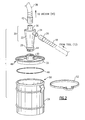
- the cyclonic separator 20 has its nose or vortex 28 oriented downward, and incorporates a male threaded pipe nipple 44.
- the coupler ring 30 of the drum lid 32 is constituted as a female threaded nipple, such that the nose 28 of the conic body 22 is screwed into the coupler ring 30 and is held rigidly in place on the drum lid.
- the lid itself is favorably formed of steel or another durable rigid material, such as any of a variety of tough plastic resins.
- a seal ring 46 formed of a suitable elastomeric material, fits onto an outer flange 48 of the lid 32, and fits against an open mouth 50 at the upper rim of the barrel or drum 34.
- the drum in this embodiment has a rigid side wall, so as to withstand the system vacuum without collapsing or crushing.
- a circumferential clamp 52 may be used here to secure the lid 32 onto the upper rim of the drum 34.
- the auxiliary dust collection device 10 is interposed in the air stream between the sander or other dust producing tool 12 and the shop vacuum or other suction source 40.
- the vacuum cleaner 40 induces an air flow through the intake conduit 18 and cyclonic separator 20, and then via the outlet pipe 36 and outlet conduit 38 to the vacuum cleaner 40.
- the air stream or air flow is represented with arrows in this view. Entrained process dust in the air stream separates out by cyclonic action in the separator 20, and this dust then precipitates from the nose 38 into the drum 34.
- the action of the vacuum cleaner 40 creates a net negative pressure, relative to ambient, within the cyclonic separator 20 and the drum 34.
- the seal ring 46 serves to prevent leakage of air into the drum 34, which could interfere with the precipitation of dust into the drum, and would also reduce efficiency of operation. Also, because this system uses a generally rigid drum, rather than a flexible bag, the system provides a calm, dead space where the separated process dust can fall and leave the air stream. The separation efficiency of this system is rather high, and between 95% and 99% of the process dust from the tool separates out from the air stream into the drum 34, with only a small amount of residual dust remaining in the air stream, and going to the vacuum cleaner 40. Consequently, the shop vacuum cleaner 40 can be run continuously for an extended period of time without clogging.
- a polyethylene bag liner may optionally be used in the drum or barrel to facilitate disposal of the collected dust. If so, a vacuum hold-down feature may be employed.
- Each length of intake hose should have a cuff 26 that is of a standard 1.5 inch (3.8 cm) inside diameter, so as to fit onto the inlet pipe 24 of the cyclonic separator.
- the hose 18 may be of a small diameter, e.g. 1.0 inch (2.5 cm), with a 1.0 inch (2.5 cm) cuff 54 at the tool end; there may be an intermediate 1.25 inch (3.2 cm) hose 18' with a 1.25 inch (3.2 cm) cuff 54' as well as a large 1.5 inch (3.8 cm) hose 18" with a 1.5 inch (3.8 cm) cuff 54" to fit tool dust conduits of those sizes.
- the larger hose sizes may also be used for general cleaning. All hoses have at least one 1.5 inch (3.8 cm) cuff to connect to the cyclone inlet.
- a tubular coupler 56 may be used for extending the hose length.
- a 1.5 inch hose 18" is run from the cyclone, then the coupler is inserted into the cuff 54" and the length of hose 18 of the desired diameter is attached to run to the tool.
- the cyclonic separator 20 is of steel construction, and is about nine inches (about 23 cm) tall, with the inlet pipe 24 being 1-1/2 inches (3.8 cm) in diameter, and the outlet pipe 36 being 2 inches (5 cm) in diameter, with the hose 38 to the vacuum cleaner 40 being 2-inch (5 cm) flexible hose.
- the drum 34 is a ten-gallon (about forty L.) capacity metal drum of about 15 inch (43 cm) diameter.
- the nose opening can have a diameter of about 7 cm.
- the overall height of the unit is about 31 inches (87 cm).
- the hoses 18, 38 are wire-reinforced static dissipating hoses.
- FIGs. 6 and 7 An alternative arrangement of the dust collection device 60 is illustrated in Figs. 6 and 7.
- This implementation is used with a tool 12', such as floor sanding edger, which has its own internal blower, so that the required air flow is produced by the tool.
- the shop vacuum cleaner is not needed.
- a cyclonic separator 20' has basically the same elements as in Figs. 1 to 3, except that there is no hose or conduit connected with the unit's outlet pipe 36.
- the separator 20' has an inlet pipe 24 and a nose or apex 28 mounted onto the drum lid 32. The hose to the tool 12' is fitted to the inlet pipe 24.
- the filter cartridge is a cylindrical pleated media high efficiency filter, e.g., a HEPA filter.
- the cylindrical filter cartridge 62 has its lower end seated onto a top surface 64 of the conic body 22 of the separator 20.
- a hold-down disk 66 fits against the top end of the filter cartridge 62, and this is held in place by a threaded rod 68 that twists into a nut 70 located within the conic body 22 along the axis of the outlet pipe.
- a ring clamp 52 secures the top or lid 32 against the mouth 50 of the drum 34.
- the tool 12' creates a positive pressure
- the clamp 52 keeps the lid and ring seal closed against the drum, to keep dust from blowing out of the drum from under the lid.
- casters or wheels 72 for the drum 34 are Another optional feature, to allow the device 60 to be pulled along to follow the work, e.g., for the sanding of floors or woodwork.
- the device 60 does not require power, as all the air flow is provided from the tool.
- a crank-operated dust shaker arrangement 80 (See Fig. 7B) can be employed to loosen the dust that collects on the inner part of the filter cartridge 62. This allows the filter cartridge 62 to be cleaned in place without having to remove it from the top 64 of the cyclonic separator. In this case, there are clamps 82 at the base of the filter 62 to hold it to the top 64 of the conic body 22 of the separator. At the top of the filter cartridge is a crank 84, formed of a disk 86 and a handle 88, with a rod 90 descending into the interior of the filter cartridge.
- a tee member 92 formed of a flexible material, e.g., Teflon, extends outward from the rod 90, and its tips extend just into the pleats 94 on the inside of the filter cartridge 62. After a few hours of operation, some dust can collect on the inner surfaces of the filter cartridge. This can be knocked off from the inside by rotating the crank 84, after turning off the air flow. The tee member 92 snaps past each of the interior pleats 94, and this shaking action loosens the collected dust, and this dust then falls down through the vortex tube 36 and into the barrel or drum.
- a small flared flange 96 favorably made of a flexible, rubber-like material, can be fitted onto the top end of the vortex tube.
- the cyclonic separator arrangement of this invention can be used anywhere that it is desired to intercept a the dust in a flow of air where the dust is entrained.
- the separator can be used in line with a vacuum cleaner, such as the vacuum cleaner unit 40, in the hose, so that the large majority of the dust picked up by the head or nozzle of the vacuum unit will be deposited in the barrel or drum, leaving only a minor amount to reach the vacuum cleaner.
- a vacuum cleaner such as the vacuum cleaner unit 40
- the vacuum unit also permits the vacuum unit to be fitted with a HEPA filter, as it is only a small amount of dust that needs to be filtered there; as a result there is less health hazard.
- the cyclonic separator arraignment can also be employed in line in a built-in central vacuum system.
- the arrangement of this invention can be employed in any environment in which the waste material being collected has posed a problem in handling and collecting, such as bone dust, animal hair, fine stone dust, or plaster dust.
- a drop-in silencer according to an embodiment of the invention is shown with reference to Figs. 8 and 9 and with further reference to Figs. 10 to 13.
- the silencer can be used with a cyclonic separator dust collection and containment system, e.g., in a wood shop environment.
- a cyclonic dust collector 110 has an air intake 112 that is connected downstream of dust producing tool (or tools), which introduces a stream of dust-laden air into a conic body 114 where the dust separates from the air stream by cyclonic action.
- a nose or vortex 116 at the bottom is connected by a conduit 118 to a dust collection drum 120. The dust that separates from the air stream precipitates out via the nose 116 and settles into the drum 120.
- a centrifugal fan or blower 122 at the top of the cyclonic separator creates an air flow out from the cyclone and through an exhaust port 124.
- a single-phase AC induction motor 126 powers the blower 122.
- the exhaust air flow passes from the exhaust port 124 and through a high performance cartridge filter 130 into the ambient room air. About 95% to 99% of the dust is removed from the air stream by the cyclonic separator, and the residual dust is caught in the filter 130.
- the cylindrical cartridge filter 130 has its axis arranged vertically, with a lower end seated on a canister-shaped base or pedestal 132.
- a connector 134 that receives the exhaust air flow from the exhaust port 124 is fastened down to an upper end of the cartridge filter.
- the filter 130 is of the type having pleated filter material forming cylindrical side wall or walls, and has annular top and bottom end walls 136, each with a circular opening.
- a flange 138 on the connector 134 clamps to the top end wall 136 of the filter, so that the exhaust air is ducted into the interior of the cartridge filter.
- the fan or blower 122 produces a significant level of noise, which can be a nuisance in a workplace environment.
- a drop-in silencer 140 is employed, as illustrated, to reduce the volume of the noise.
- the silencer 140 is formed of a tube or cylinder 142 of an acoustic foam.
- a transverse flange 144 extends radially out from the top end of the tube 142. This can be made at least partly of a semi-flexible compressible material so as to form a seal between the flange 138 and the top end 136 of the filter cartridge.
- noise from the blower 124 is ducted with the air flow into the cartridge 130, and can escape from there into the workplace.
- the silencer 140 absorbs a significant amount of the noise, especially at the more annoying frequencies above 2 KHz.
- the silencer is generally cylindrical in shape, and conforms with the interior diameter of the cylindrical filter cartridge 130.
- the acoustic foam has a textured surface 146 at the interior side of the tube, i.e., on the sound-facing side.
- the acoustic foam may have a thickness of 1/4 inch, 3/8 inch or 1 ⁇ 2 inch.
- the tube length of the silencer 140 is about one-quarter to one-third the length of the cartridge 130.
- the silencer is effective in reducing the noise levels by about 2 dB to 8 dB, at least for frequencies above about 2 KHz.
- baffles 148 (Fig. 11) may be formed in the interior of the acoustic foam tube to enhance its noise suppression.
- the baffles may be formed of the same acoustic foam, or may be formed of other materials.
Landscapes
- Chemical & Material Sciences (AREA)
- Chemical Kinetics & Catalysis (AREA)
- Engineering & Computer Science (AREA)
- Mechanical Engineering (AREA)
- Filters For Electric Vacuum Cleaners (AREA)
- Filtering Of Dispersed Particles In Gases (AREA)
Applications Claiming Priority (1)
| Application Number | Priority Date | Filing Date | Title |
|---|---|---|---|
| US11/413,729 US7282074B1 (en) | 2006-04-28 | 2006-04-28 | Auxiliary dust collection system |
Publications (1)
| Publication Number | Publication Date |
|---|---|
| EP1849512A1 true EP1849512A1 (de) | 2007-10-31 |
Family
ID=38169492
Family Applications (1)
| Application Number | Title | Priority Date | Filing Date |
|---|---|---|---|
| EP07251602A Withdrawn EP1849512A1 (de) | 2006-04-28 | 2007-04-16 | Zusätzliches Staubsammelsystem |
Country Status (2)
| Country | Link |
|---|---|
| US (1) | US7282074B1 (de) |
| EP (1) | EP1849512A1 (de) |
Cited By (3)
| Publication number | Priority date | Publication date | Assignee | Title |
|---|---|---|---|---|
| US10420867B2 (en) | 2015-10-19 | 2019-09-24 | Conmed Corporation | Liquid-gas Separator |
| US11440029B2 (en) | 2020-10-13 | 2022-09-13 | Mullet Tools, LLC | Monolithic dust separator |
| US12156630B2 (en) | 2020-08-27 | 2024-12-03 | Mullet Tools, LLC | Monolithic dust separator |
Families Citing this family (131)
| Publication number | Priority date | Publication date | Assignee | Title |
|---|---|---|---|---|
| GB0500469D0 (en) * | 2005-01-11 | 2005-02-16 | Positec Group Ltd | Tool |
| US7485167B2 (en) * | 2005-06-15 | 2009-02-03 | Vac-U-Max | Shaker mechanism for vacuum cleaner filter bag |
| US7937803B2 (en) * | 2005-07-26 | 2011-05-10 | Witter Robert M | Bag hold-down for dust collection system |
| SE530731C2 (sv) * | 2005-12-07 | 2008-08-26 | Atlas Copco Tools Ab | Elektrisk portabel slipmaskin med luftkylningssystem |
| SE530665C2 (sv) * | 2005-12-21 | 2008-08-05 | Atlas Copco Rock Drills Ab | Borrkaxseparator, borrigg och metod för att styra en borrkaxseparator |
| US7662199B2 (en) * | 2007-03-07 | 2010-02-16 | Tennant Company | Cyclonic filter for surface maintenance machine |
| US8012230B2 (en) * | 2007-07-30 | 2011-09-06 | Ging-Chung Chen | Structure of an impurities collecting bucket for an air separator and purifier |
| US9427813B2 (en) | 2007-07-31 | 2016-08-30 | Newell Window Furnishing, Inc. | Window covering sizing method and apparatus |
| US8070862B2 (en) * | 2007-09-04 | 2011-12-06 | 3M Innovative Properties Company | Dust collection device for sanding tool |
| US20090139048A1 (en) * | 2007-11-30 | 2009-06-04 | Williams Danny P | Power tool dust-collecting assembly and accessories |
| EP2247360B1 (de) * | 2007-12-27 | 2020-04-15 | 3M Innovative Properties Company | Staubsammelvorrichtung für schleifwerkzeug |
| US7905260B2 (en) * | 2008-01-12 | 2011-03-15 | Richard Keenan | Router dust collection assembly |
| US8034143B2 (en) * | 2008-03-18 | 2011-10-11 | Uti Limited Partnership | Cyclone |
| US20100257826A1 (en) * | 2008-03-26 | 2010-10-14 | Kun-Yen Lin | Dust Collector |
| US8161597B2 (en) * | 2008-06-16 | 2012-04-24 | Oneida Air Systems, Inc. | Shop vacuum cleaner with cyclonic separator |
| US20100132317A1 (en) * | 2008-11-21 | 2010-06-03 | Thien J Philip | Dust separator |
| US8029590B2 (en) * | 2008-11-26 | 2011-10-04 | San Ford Machinery Co., Ltd. | Collapsible filtration tank for a dust collector |
| US8382872B2 (en) | 2008-12-23 | 2013-02-26 | 3M Innovative Properties Company | Dust collection device for sanding tool |
| US8286299B2 (en) * | 2009-01-26 | 2012-10-16 | Danny Patrick Williams | Handheld canister vacuum cleaner |
| US7824457B2 (en) * | 2009-03-02 | 2010-11-02 | Witter Robert M | Portable cyclonic dust collector |
| WO2010102210A1 (en) * | 2009-03-05 | 2010-09-10 | Pelletsales.Com, Llc | Hod system |
| US7998316B2 (en) | 2009-03-17 | 2011-08-16 | Suncoke Technology And Development Corp. | Flat push coke wet quenching apparatus and process |
| CN101927116B (zh) * | 2009-06-22 | 2014-02-19 | 上海佳维特机械设备有限公司 | 液膜抑尘装置 |
| CN101927252B (zh) * | 2009-06-22 | 2013-12-04 | 上海佳维特机械设备有限公司 | 液膜抑尘方法 |
| USD638179S1 (en) | 2009-08-31 | 2011-05-17 | Witter Robert M | Auxiliary cyclonic dust collector |
| US20110088727A1 (en) * | 2009-10-15 | 2011-04-21 | Slowe Daniel J | Air duct cleaning system and method |
| US9399184B2 (en) * | 2009-10-28 | 2016-07-26 | Oneida Air Systems, Inc. | Deflagration suppression screen for portable cyclonic dust collector/vacuum cleaner |
| US8393050B2 (en) * | 2009-10-28 | 2013-03-12 | Robert M. Witter | Portable cyclonic dust collector/vacuum cleaner |
| US8337580B2 (en) | 2010-09-03 | 2012-12-25 | Manska Wayne E | Debris separator |
| US9555357B2 (en) | 2010-10-14 | 2017-01-31 | Air Dynamics Industrial Systems Corporation | Filter chambers and self-cleaning apparatus for vacuum systems |
| US8888880B2 (en) * | 2010-10-14 | 2014-11-18 | Air Dynamics Industrial Systems Corporation | Vacuum loader |
| US8348727B2 (en) * | 2011-05-26 | 2013-01-08 | Black & Decker Inc. | Airflow arrangement for a power tool |
| US9656816B2 (en) * | 2011-08-12 | 2017-05-23 | Cyclone Catalyst Properties Llc | Systems and methods for converter bed unloading and loading |
| CN103128091B (zh) * | 2011-11-30 | 2015-03-18 | 研能科技股份有限公司 | 粉末自动回收系统 |
| US9393658B2 (en) | 2012-06-14 | 2016-07-19 | Black & Decker Inc. | Portable power tool |
| DE102012012727A1 (de) * | 2012-06-26 | 2014-01-02 | Hydac Process Technology Gmbh | Vorrichtung zur Konditionierung von Gasen |
| EP2879777B1 (de) * | 2012-07-31 | 2019-05-29 | SunCoke Technology and Development LLC | Verfahren zur handhabung von kohleemissionen sowie zugehörige systeme und vorrichtungen |
| CN103566680B (zh) * | 2012-08-03 | 2015-09-16 | 武汉博硕聚才科技有限公司 | 气体分离器 |
| US9243186B2 (en) | 2012-08-17 | 2016-01-26 | Suncoke Technology And Development Llc. | Coke plant including exhaust gas sharing |
| US9359554B2 (en) | 2012-08-17 | 2016-06-07 | Suncoke Technology And Development Llc | Automatic draft control system for coke plants |
| US9169439B2 (en) | 2012-08-29 | 2015-10-27 | Suncoke Technology And Development Llc | Method and apparatus for testing coal coking properties |
| KR101272428B1 (ko) * | 2012-11-14 | 2013-06-07 | 최무송 | 집진 장치가 일체로 구비된 라우팅 장치 |
| WO2014105062A1 (en) | 2012-12-28 | 2014-07-03 | Suncoke Technology And Development Llc. | Systems and methods for removing mercury from emissions |
| WO2014105065A1 (en) | 2012-12-28 | 2014-07-03 | Suncoke Technology And Development Llc. | Vent stack lids and associated systems and methods |
| US9476547B2 (en) | 2012-12-28 | 2016-10-25 | Suncoke Technology And Development Llc | Exhaust flow modifier, duct intersection incorporating the same, and methods therefor |
| US10883051B2 (en) | 2012-12-28 | 2021-01-05 | Suncoke Technology And Development Llc | Methods and systems for improved coke quenching |
| US9238778B2 (en) | 2012-12-28 | 2016-01-19 | Suncoke Technology And Development Llc. | Systems and methods for improving quenched coke recovery |
| US10760002B2 (en) | 2012-12-28 | 2020-09-01 | Suncoke Technology And Development Llc | Systems and methods for maintaining a hot car in a coke plant |
| US10047295B2 (en) | 2012-12-28 | 2018-08-14 | Suncoke Technology And Development Llc | Non-perpendicular connections between coke oven uptakes and a hot common tunnel, and associated systems and methods |
| US9273250B2 (en) | 2013-03-15 | 2016-03-01 | Suncoke Technology And Development Llc. | Methods and systems for improved quench tower design |
| US20140352268A1 (en) * | 2013-05-31 | 2014-12-04 | Eric Wilson | Cyclonic particulate collection device |
| US9107550B2 (en) * | 2013-09-27 | 2015-08-18 | Black & Decker Inc. | Compact vacuum and sander |
| WO2015069292A1 (en) * | 2013-11-11 | 2015-05-14 | Halliburton Energy Services Inc. | Mobile multi sack dust collection apparatus |
| US9004989B1 (en) * | 2013-11-27 | 2015-04-14 | Mark A. Ogier | Vacuum apparatus and product recovery method |
| BR112016015475B1 (pt) | 2013-12-31 | 2021-02-17 | Suncoke Technology And Development Llc | método de descarbonização de um forno de coque de depósitos de coque e sistema de coqueificação |
| US10526541B2 (en) | 2014-06-30 | 2020-01-07 | Suncoke Technology And Development Llc | Horizontal heat recovery coke ovens having monolith crowns |
| PL3186340T3 (pl) | 2014-08-28 | 2021-04-19 | Suncoke Technology And Development Llc | Sposób i system do optymalizacji i wydajności instalacji koksowniczej |
| US10843112B2 (en) * | 2014-08-29 | 2020-11-24 | Nabtesco Automotive Corporation | Oil separator and compressed air drying system |
| US20160067719A1 (en) * | 2014-09-08 | 2016-03-10 | Ivo Fill | Hybrid cyclone mist collector |
| RU2702546C2 (ru) | 2014-09-15 | 2019-10-08 | САНКОУК ТЕКНОЛОДЖИ ЭНД ДИВЕЛОПМЕНТ ЭлЭлСи | Коксовые печи, имеющие конструкцию из монолитных компонентов |
| US10036319B2 (en) * | 2014-10-31 | 2018-07-31 | General Electric Company | Separator assembly for a gas turbine engine |
| US9573248B2 (en) * | 2014-12-02 | 2017-02-21 | Zulluboy, Inc. | Foreign object removal for abrasive recycling system |
| WO2016109704A1 (en) | 2014-12-31 | 2016-07-07 | Suncoke Technology And Development Llc | Multi-modal beds of coking material |
| EP3240862A4 (de) | 2015-01-02 | 2018-06-20 | Suncoke Technology and Development LLC | Automatisierung und optimierung einer integrierten verkokungsanlage unter verwendung von erweiterten steuerungs- und optimierungstechniken |
| US11060032B2 (en) | 2015-01-02 | 2021-07-13 | Suncoke Technology And Development Llc | Integrated coke plant automation and optimization using advanced control and optimization techniques |
| SE538760C2 (sv) * | 2015-03-12 | 2016-11-15 | Valmet Oy | Cyclone separator arrangement and method |
| US20160279759A1 (en) * | 2015-03-24 | 2016-09-29 | Full Circle International, Inc. | Hand sander vacuum adapter |
| US10016712B2 (en) * | 2015-05-07 | 2018-07-10 | JPL Global, LLC | Portable system and methodology that facilitates dust collection within a silo apparatus |
| US9579773B2 (en) | 2015-07-31 | 2017-02-28 | Zuluboy, Inc. | Control loop for abrasive recycling system |
| US10654149B2 (en) | 2015-08-06 | 2020-05-19 | Hypertherm, Inc. | Abrasive recycling system |
| CN118990696A (zh) * | 2015-08-31 | 2024-11-22 | Jpl环球公司 | 锯设备 |
| CN105364625B (zh) * | 2015-12-01 | 2018-01-26 | 重庆光大机械厂有限公司 | 同轴式车床铁屑回收装置 |
| WO2017117282A1 (en) | 2015-12-28 | 2017-07-06 | Suncoke Technology And Development Llc | Method and system for dynamically charging a coke oven |
| US10232204B2 (en) * | 2016-01-04 | 2019-03-19 | David Hakes | Explosion isolation device and method for disposing dust |
| RU2746968C2 (ru) | 2016-06-03 | 2021-04-22 | САНКОУК ТЕКНОЛОДЖИ ЭНД ДИВЕЛОПМЕНТ ЭлЭлСи. | Способы и системы для автоматического создания корректирующих действий в промышленном объекте |
| US10189134B2 (en) * | 2016-12-08 | 2019-01-29 | GM Global Technology Operations LLC | Indexable plenum |
| US11794141B2 (en) * | 2021-01-25 | 2023-10-24 | Omachron Intellectual Property Inc. | Multiuse home station |
| WO2018188736A1 (de) * | 2017-04-11 | 2018-10-18 | Festool Gmbh | Zyklonvorabscheider und anordnung |
| JP7154231B2 (ja) | 2017-05-23 | 2022-10-17 | サンコーク テクノロジー アンド ディベロップメント リミテッド ライアビリティ カンパニー | コークス炉を補修するシステムおよび方法 |
| US10363511B2 (en) * | 2017-05-26 | 2019-07-30 | San Ford Machinery Co., Ltd. | Dust collector provided with a shunt guide plate |
| SE541077C2 (en) * | 2017-09-05 | 2019-03-26 | Husqvarna Ab | Separator, separator system and methods of their operation |
| EP3488751B1 (de) * | 2017-11-22 | 2023-06-07 | Guido Valentini | Staubsauger |
| CN111511474B (zh) * | 2017-12-19 | 2022-06-07 | 利乐拉瓦尔集团及财务有限公司 | 用于分离牛奶的分离器和方法 |
| US11235433B2 (en) | 2017-12-22 | 2022-02-01 | Milwaukee Electric Tool Corporation | Dust collector with filter cleaning mechanism |
| CN108096963A (zh) * | 2018-01-25 | 2018-06-01 | 洛阳明创矿山冶金设备有限公司 | 一种冶金矿山开采用粉尘治理装置 |
| US11452962B2 (en) * | 2018-08-10 | 2022-09-27 | Imperial Systems, Inc. | Explosion proof drum kit |
| CN215968574U (zh) | 2018-11-19 | 2022-03-08 | 米沃奇电动工具公司 | 适于与手持式电动工具一起使用的集尘器 |
| BR112021012718B1 (pt) | 2018-12-28 | 2022-05-10 | Suncoke Technology And Development Llc | Sistema para detecção de particulado para uso em uma instalação industrial e método para detecção de particulado em uma instalação de gás industrial |
| BR112021012500B1 (pt) | 2018-12-28 | 2024-01-30 | Suncoke Technology And Development Llc | Duto coletor ascendente, sistema de gás de escape para um forno de coque, e forno de coque |
| BR112021012725B1 (pt) | 2018-12-28 | 2024-03-12 | Suncoke Technology And Development Llc | Método para reparar um vazamento em um forno de coque de uma coqueria, método de reparo da superfície de um forno de coque configurado para operar sob pressão negativa e tendo um piso de forno, uma câmara de forno e uma chaminé única e método de controle de ar descontrolado em um sistema para carvão de coque |
| BR112021012766B1 (pt) | 2018-12-28 | 2023-10-31 | Suncoke Technology And Development Llc | Descarbonização de fornos de coque e sistemas e métodos associados |
| WO2020140092A1 (en) | 2018-12-28 | 2020-07-02 | Suncoke Technology And Development Llc | Heat recovery oven foundation |
| WO2020140095A1 (en) | 2018-12-28 | 2020-07-02 | Suncoke Technology And Development Llc | Spring-loaded heat recovery oven system and method |
| WO2020142389A1 (en) | 2018-12-31 | 2020-07-09 | Suncoke Technology And Development Llc | Improved systems and methods for utilizing flue gas |
| BR112021012952A2 (pt) | 2018-12-31 | 2021-09-08 | Suncoke Technology And Development Llc | Métodos e sistemas para fornecer superfícies resistentes a corrosão em sistemas de tratamento de contaminantes |
| US11291340B2 (en) | 2019-03-01 | 2022-04-05 | Troy Taylor | Paint booth filter |
| US11458485B2 (en) * | 2019-07-03 | 2022-10-04 | Oneida Air Systems, Inc. | Dust collector with negative pressure bagging |
| US11446705B2 (en) * | 2019-07-12 | 2022-09-20 | Donald Maynard | Dust and particle separator with vortical action |
| TWI721721B (zh) * | 2019-12-20 | 2021-03-11 | 昌澤機械股份有限公司 | 集塵裝置之拆卸機構及包括二該拆卸機構之集塵裝置 |
| WO2021134071A1 (en) | 2019-12-26 | 2021-07-01 | Suncoke Technology And Development Llc | Oven health optimization systems and methods |
| US11419467B2 (en) | 2020-01-23 | 2022-08-23 | Oneida Air Systems, Inc. | Bucket lid for auxiliary cyclone dust collector |
| WO2021195339A1 (en) | 2020-03-25 | 2021-09-30 | Milwaukee Electric Tool Corporation | Dust collector assembly |
| EP4146767A4 (de) | 2020-05-03 | 2024-07-31 | Suncoke Technology and Development LLC | Koksprodukte hoher qualität |
| DE102020209204A1 (de) * | 2020-07-22 | 2022-01-27 | Robert Bosch Gesellschaft mit beschränkter Haftung | Modulares Luftreinigungssystem |
| CN111996775B (zh) * | 2020-08-26 | 2021-11-02 | 蠡县博亚服装有限公司 | 裘皮浮毛分离器 |
| CN114308971A (zh) * | 2020-09-27 | 2022-04-12 | 湖南绿生永固新材料有限公司 | 一种建筑材料加工用收集装置 |
| CN112247743A (zh) * | 2020-10-14 | 2021-01-22 | 无锡市业成机械设备制造有限公司 | 一种具有辅助抗振吸阻尼功能的数控机床 |
| US12357136B2 (en) | 2020-11-19 | 2025-07-15 | Milwaukee Electric Tool Corporation | Portable dust extractor |
| US11910989B2 (en) * | 2021-02-25 | 2024-02-27 | Techtronic Cordless Gp | Integrated cyclonic separator in a wet-dry vacuum |
| US12048411B2 (en) * | 2021-04-21 | 2024-07-30 | Battelle Energy Alliance, Llc | Modular particle collection system and related methods |
| AU2022270111A1 (en) | 2021-05-04 | 2023-11-23 | Suncoke Technology And Development Llc | Foundry coke products, and associated systems and methods |
| US12091264B2 (en) | 2021-07-08 | 2024-09-17 | Industrial Vacuum Transfer Services Usa, Llc | Assemblies, apparatuses, systems, and methods for material extraction and conveyance |
| US12137864B2 (en) | 2021-07-08 | 2024-11-12 | Industrial Vacuum Transfer Services Usa, Llc | Assemblies and methods for material extraction |
| US12485459B2 (en) | 2021-07-08 | 2025-12-02 | Industrial Vacuum Transfer Services Usa, Llc | Systems, assemblies, and methods for pyrophoric material extraction |
| US12098068B2 (en) * | 2021-07-08 | 2024-09-24 | Industrial Vacuum Transfer Services Usa, Llc | Systems, methods, and devices for industrial tower waste extraction |
| US12510077B2 (en) | 2021-07-08 | 2025-12-30 | Industrial Vacuum Transfer Services Usa, Llc | Air compressor having vacuum and associated methods for loading and extracting materials |
| US12193627B2 (en) | 2021-07-08 | 2025-01-14 | Industrial Vacuum Transfer Services Usa, Llc | High volume industrial vacuum assemblies and methods |
| US12103791B2 (en) | 2021-07-08 | 2024-10-01 | Industrial Vacuum Transfer Services Usa, Llc | Assemblies and methods for material extraction from retention collections |
| US12246932B2 (en) * | 2021-07-08 | 2025-03-11 | Industrial Vacuum Transfer Services Usa, Llc | Methods for loading and extracting product in elevated tower |
| CN113510011B (zh) * | 2021-08-01 | 2026-03-06 | 苏州欧圣电气股份有限公司 | 垃圾收集器 |
| USD1041109S1 (en) * | 2021-08-24 | 2024-09-03 | Suzhou Alton Electrical & Mechanical Industry Co., Ltd. | Cyclonic dust collector |
| US11904328B2 (en) * | 2021-08-30 | 2024-02-20 | Spinesmith Partners, L.P. | Induction powered vortex fluid separator |
| CN115193199B (zh) * | 2021-09-29 | 2024-02-02 | 湖南云箭集团有限公司 | 一种避免溢粉的粉料收集器 |
| US11946108B2 (en) | 2021-11-04 | 2024-04-02 | Suncoke Technology And Development Llc | Foundry coke products and associated processing methods via cupolas |
| EP4426799A4 (de) | 2021-11-04 | 2025-09-17 | Suncoke Tech & Development Llc | Giesskoksprodukte und zugehörige systeme, vorrichtungen und verfahren |
| CN114110870B (zh) * | 2021-11-25 | 2023-04-07 | 宋新苗 | 一种具备双净化系统的智能环保空气净化装置 |
| USD1056378S1 (en) | 2022-03-29 | 2024-12-31 | Onedia Air Systems Inc. | Dust separator part |
| CN114670075B (zh) * | 2022-05-30 | 2022-08-26 | 昆山华恒焊接股份有限公司 | 管道端面打磨设备 |
| US12110458B2 (en) | 2022-11-04 | 2024-10-08 | Suncoke Technology And Development Llc | Coal blends, foundry coke products, and associated systems, devices, and methods |
| US12172253B1 (en) * | 2023-07-28 | 2024-12-24 | Gilbert Otis Rabbe, Jr. | Debris management system for both positive and negative pressure dust collectors |
| US12410369B2 (en) | 2023-11-21 | 2025-09-09 | Suncoke Technology And Development Llc | Flat push hot car for foundry coke and associated systems and methods |
Citations (7)
| Publication number | Priority date | Publication date | Assignee | Title |
|---|---|---|---|---|
| US6027541A (en) * | 1998-04-08 | 2000-02-22 | Lee Valley Tools Ltd. | Lid for auxiliary dust removal receptacle |
| DE10047274A1 (de) * | 2000-09-21 | 2002-05-02 | Peter Meede | Vorsammler |
| JP2002126968A (ja) * | 2000-10-24 | 2002-05-08 | Mitsubishi Materials Corp | 切削装置 |
| DE10102924C1 (de) * | 2001-01-23 | 2002-06-13 | Pieper Innovationsgmbh | Verfahren und Vorrichtung zum Strahlbearbeiten, insbesondere formgenauen Abtragen und/oder Verdichten und/oder Beschichten, von festen Flächen |
| US6471751B1 (en) * | 2000-09-11 | 2002-10-29 | Houston Industrial Corporation | Polycyclonic vacuum collectors for virtually non-stop environmental remediation |
| US20040187449A1 (en) * | 2003-03-27 | 2004-09-30 | Oneida Air Systems, Inc. | Dust collection system |
| WO2006027977A1 (ja) * | 2004-09-08 | 2006-03-16 | Max Co., Ltd. | 穿孔工具 |
Family Cites Families (9)
| Publication number | Priority date | Publication date | Assignee | Title |
|---|---|---|---|---|
| US2575148A (en) * | 1948-09-28 | 1951-11-13 | Vokes Ltd | Dust collector filter |
| US3485671A (en) * | 1966-12-19 | 1969-12-23 | Food Products Inc | Method of cleaning air supply systems and ducts |
| US3899311A (en) * | 1972-04-20 | 1975-08-12 | Herbert Rapp | Recovery of powder in an electrostatic powder spraying operation |
| SE434469B (sv) * | 1982-12-13 | 1984-07-30 | Soederhamn Ind Arbetshygien Ab | Stoftavskiljaraggregat |
| US5104429A (en) * | 1990-07-20 | 1992-04-14 | Kinlau Sheet Metal Works, Inc. | Self-cleaning gas filtration apparatus and methods |
| US5045098A (en) * | 1990-08-13 | 1991-09-03 | The Spencer Turbine Company | Bag separator |
| US5746795A (en) * | 1995-12-18 | 1998-05-05 | Witter; Robert | Replaceable, self-cleaning cartridge for a cyclonic air cleaning device |
| US6129775A (en) * | 1998-08-19 | 2000-10-10 | G.B.D. Corp. | Terminal insert for a cyclone separator |
| US7485167B2 (en) * | 2005-06-15 | 2009-02-03 | Vac-U-Max | Shaker mechanism for vacuum cleaner filter bag |
-
2006
- 2006-04-28 US US11/413,729 patent/US7282074B1/en not_active Expired - Lifetime
-
2007
- 2007-04-16 EP EP07251602A patent/EP1849512A1/de not_active Withdrawn
Patent Citations (7)
| Publication number | Priority date | Publication date | Assignee | Title |
|---|---|---|---|---|
| US6027541A (en) * | 1998-04-08 | 2000-02-22 | Lee Valley Tools Ltd. | Lid for auxiliary dust removal receptacle |
| US6471751B1 (en) * | 2000-09-11 | 2002-10-29 | Houston Industrial Corporation | Polycyclonic vacuum collectors for virtually non-stop environmental remediation |
| DE10047274A1 (de) * | 2000-09-21 | 2002-05-02 | Peter Meede | Vorsammler |
| JP2002126968A (ja) * | 2000-10-24 | 2002-05-08 | Mitsubishi Materials Corp | 切削装置 |
| DE10102924C1 (de) * | 2001-01-23 | 2002-06-13 | Pieper Innovationsgmbh | Verfahren und Vorrichtung zum Strahlbearbeiten, insbesondere formgenauen Abtragen und/oder Verdichten und/oder Beschichten, von festen Flächen |
| US20040187449A1 (en) * | 2003-03-27 | 2004-09-30 | Oneida Air Systems, Inc. | Dust collection system |
| WO2006027977A1 (ja) * | 2004-09-08 | 2006-03-16 | Max Co., Ltd. | 穿孔工具 |
Cited By (4)
| Publication number | Priority date | Publication date | Assignee | Title |
|---|---|---|---|---|
| US10420867B2 (en) | 2015-10-19 | 2019-09-24 | Conmed Corporation | Liquid-gas Separator |
| US12156630B2 (en) | 2020-08-27 | 2024-12-03 | Mullet Tools, LLC | Monolithic dust separator |
| US11440029B2 (en) | 2020-10-13 | 2022-09-13 | Mullet Tools, LLC | Monolithic dust separator |
| USD1049527S1 (en) | 2020-10-13 | 2024-10-29 | Mullet Tools, LLC | Monolithic dust separator |
Also Published As
| Publication number | Publication date |
|---|---|
| US20070251198A1 (en) | 2007-11-01 |
| US7282074B1 (en) | 2007-10-16 |
Similar Documents
| Publication | Publication Date | Title |
|---|---|---|
| US7282074B1 (en) | Auxiliary dust collection system | |
| US7247180B1 (en) | Silencer for dust collection system | |
| US7550021B2 (en) | Portable cyclonic dust collection system | |
| US8393050B2 (en) | Portable cyclonic dust collector/vacuum cleaner | |
| US9125535B2 (en) | Pulse filter cleaner for portable cyclonic dust collector/vacuum cleaner | |
| US7824457B2 (en) | Portable cyclonic dust collector | |
| EP1462179B1 (de) | System zum Sammeln von Staub | |
| US8161597B2 (en) | Shop vacuum cleaner with cyclonic separator | |
| US4646482A (en) | Recirculating sandblasting machine | |
| US11458485B2 (en) | Dust collector with negative pressure bagging | |
| US9399184B2 (en) | Deflagration suppression screen for portable cyclonic dust collector/vacuum cleaner | |
| CN1192742C (zh) | 吸尘器的垃圾收集容器 | |
| JP2004358442A (ja) | 粉塵類の回収装置 | |
| CN1361673A (zh) | 真空吸尘器 | |
| US7937803B2 (en) | Bag hold-down for dust collection system | |
| CN1958129A (zh) | 真空装载机 | |
| JP2008263830A (ja) | 葉たばこ作業台の湿式集塵装置 | |
| US5775979A (en) | Enclosed abrasive blasting apparatus | |
| MXPA02002547A (es) | Aparato obturador antipolvo para maquinas de piso. | |
| CN209491152U (zh) | 一种集尘设备 | |
| JP3214995U (ja) | 集塵装置 | |
| JP2003061878A (ja) | 電気掃除機 | |
| JPS61191329A (ja) | ろ過用のフイルタを不要にしたアツプライト型真空掃除機 | |
| CN222520766U (zh) | 一种用于室内装修的墙面打磨装置 | |
| CN217490108U (zh) | 一种煤磨布袋除尘器 |
Legal Events
| Date | Code | Title | Description |
|---|---|---|---|
| PUAI | Public reference made under article 153(3) epc to a published international application that has entered the european phase |
Free format text: ORIGINAL CODE: 0009012 |
|
| AK | Designated contracting states |
Kind code of ref document: A1 Designated state(s): AT BE BG CH CY CZ DE DK EE ES FI FR GB GR HU IE IS IT LI LT LU LV MC MT NL PL PT RO SE SI SK TR |
|
| AX | Request for extension of the european patent |
Extension state: AL BA HR MK YU |
|
| 17P | Request for examination filed |
Effective date: 20080410 |
|
| 17Q | First examination report despatched |
Effective date: 20080530 |
|
| AKX | Designation fees paid |
Designated state(s): AT BE BG CH CY CZ DE DK EE ES FI FR GB GR HU IE IS IT LI LT LU LV MC MT NL PL PT RO SE SI SK TR |
|
| STAA | Information on the status of an ep patent application or granted ep patent |
Free format text: STATUS: THE APPLICATION IS DEEMED TO BE WITHDRAWN |
|
| 18D | Application deemed to be withdrawn |
Effective date: 20110607 |