EP1849965B1 - Kühlung der Plattform einer Leitschaufel - Google Patents
Kühlung der Plattform einer Leitschaufel Download PDFInfo
- Publication number
- EP1849965B1 EP1849965B1 EP07250726.2A EP07250726A EP1849965B1 EP 1849965 B1 EP1849965 B1 EP 1849965B1 EP 07250726 A EP07250726 A EP 07250726A EP 1849965 B1 EP1849965 B1 EP 1849965B1
- Authority
- EP
- European Patent Office
- Prior art keywords
- platform
- platform cooling
- plenum
- casting
- cluster
- Prior art date
- Legal status (The legal status is an assumption and is not a legal conclusion. Google has not performed a legal analysis and makes no representation as to the accuracy of the status listed.)
- Active
Links
Images


Classifications
-
- F—MECHANICAL ENGINEERING; LIGHTING; HEATING; WEAPONS; BLASTING
- F01—MACHINES OR ENGINES IN GENERAL; ENGINE PLANTS IN GENERAL; STEAM ENGINES
- F01D—NON-POSITIVE DISPLACEMENT MACHINES OR ENGINES, e.g. STEAM TURBINES
- F01D5/00—Blades; Blade-carrying members; Heating, heat-insulating, cooling or antivibration means on the blades or the members
- F01D5/12—Blades
- F01D5/14—Form or construction
- F01D5/18—Hollow blades, i.e. blades with cooling or heating channels or cavities; Heating, heat-insulating or cooling means on blades
- F01D5/186—Film cooling
-
- F—MECHANICAL ENGINEERING; LIGHTING; HEATING; WEAPONS; BLASTING
- F01—MACHINES OR ENGINES IN GENERAL; ENGINE PLANTS IN GENERAL; STEAM ENGINES
- F01D—NON-POSITIVE DISPLACEMENT MACHINES OR ENGINES, e.g. STEAM TURBINES
- F01D25/00—Component parts, details, or accessories, not provided for in, or of interest apart from, other groups
- F01D25/08—Cooling; Heating; Heat-insulation
- F01D25/12—Cooling
-
- F—MECHANICAL ENGINEERING; LIGHTING; HEATING; WEAPONS; BLASTING
- F05—INDEXING SCHEMES RELATING TO ENGINES OR PUMPS IN VARIOUS SUBCLASSES OF CLASSES F01-F04
- F05D—INDEXING SCHEME FOR ASPECTS RELATING TO NON-POSITIVE-DISPLACEMENT MACHINES OR ENGINES, GAS-TURBINES OR JET-PROPULSION PLANTS
- F05D2240/00—Components
- F05D2240/80—Platforms for stationary or moving blades
- F05D2240/81—Cooled platforms
-
- Y—GENERAL TAGGING OF NEW TECHNOLOGICAL DEVELOPMENTS; GENERAL TAGGING OF CROSS-SECTIONAL TECHNOLOGIES SPANNING OVER SEVERAL SECTIONS OF THE IPC; TECHNICAL SUBJECTS COVERED BY FORMER USPC CROSS-REFERENCE ART COLLECTIONS [XRACs] AND DIGESTS
- Y02—TECHNOLOGIES OR APPLICATIONS FOR MITIGATION OR ADAPTATION AGAINST CLIMATE CHANGE
- Y02T—CLIMATE CHANGE MITIGATION TECHNOLOGIES RELATED TO TRANSPORTATION
- Y02T50/00—Aeronautics or air transport
- Y02T50/60—Efficient propulsion technologies, e.g. for aircraft
Definitions
- the invention relates to cooling of high temperature components. More particularly, the Invention relates to film cooling of gas turbine engine components.
- Exemplary components are gas turbine engine blades and vanes.
- Exemplary blades and vanes airfoils are cooled by airflow directed through the airfoil to be discharged from cooling holes in the airfoil surface.
- the cooling mechanisms may include both direct cooling as the airflow passes through the component and film cooling after the airflow has been discharged from the component but passes downstream close to the component exterior surface.
- cooled vanes are found in US 5413458 , 5344283 , US 2005/0135923 , US 4218178 , US 2005/135925 . US 5743708 . EP 0974733 and JP 5-052102 .
- Exemplary cooled vanes are formed by an investment casting process.
- a sacrificial material e.g., wax
- cores e.g., refractory metal cores and/or ceramic cores
- the pattern is shelled.
- the shell is dewaxed.
- Alloy e.g., nickel- or cobalt- based superalloy
- the shell and core(s) may be destructively removed (e.g., by mechanical means and chemical means, respectively).
- the casting may be finish machined (Including surface machining and drilling of holes/passageways).
- the casting may be coated with a thermal and/or erosion-resistant coating.
- one aspect of the Invention involves in accordance with claim 1 a vane cluster having a plalform, a shroud, and at least first and second airfoils extending between an outer face of the platform and an inner face of the shroud.
- Each airfoil has a pressure side and a suction side.
- the pressure side of the first airfoil faces the suction side of the second airfoil.
- the platform, shroud and airfoils are formed as a single casting.
- the cluster includes a cooling passageway system.
- the system inclules at least one inlet in the shroud.
- At least one first feed passageway extends from the shroud to the platform through the first airfoil.
- At least one second feed passageway extends from the shroud to the platform through the second airfoil.
- a first platform cooling plenum is to the pressure side of the first airfoil.
- a second platform coollng plenum is to the suction side of the first airfoil.
- First and second pluralities of passageways extend to respective first and second pluralities of outlet holes in first and second circumferential ends of the platform.
- the cluster includes a casting essentlelly forming the shroud, airfoils, and a majority of the platform.
- the cluster may include one or more covers enclosing the first and second platform cooling plenums.
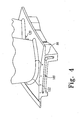
- FIG. 1 shows a gas turbine engine 20 having a central longitudinal axis 500 and extending from an upstream inlet 22 to a downstream outlet 24.
- the engine may have a number of sections along a core flowpath.
- the sections may include a low speed/pressure compressor (LPC) 30, a high speed/pressure compressor (HPC) 32, a combustor 34, a high speed/pressure turbine (HPT) 36, a low speed/pressure turbine (LPT) 38, an augmentor 40, and an exhaust duct/nozzle 42.
- LPC low speed/pressure compressor
- HPC high speed/pressure compressor
- HPT high speed/pressure turbine
- LPT low speed/pressure turbine
- one or more of the vane stages may be formed as a cluster ring.
- a second vane stage 50 of the HPT 36 is schematically shown in FIG. 1.
- FIG. 2 shows further details of the exemplary vane stage 50.
- the ring includes an inboard platform 52 and an outboard shroud 54.
- a circumferential array of airfoils (discussed below) span between the platform and shroud.
- the ring may be segmented into a plurality of separately-formed clusters interlocked at the platforms by a structural ring 56 and at the shrouds by an engine case.
- FIG. 3 shows an exemplary two-airfoil cluster 60.
- Each exemplary cluster includes a first airfoil 62 and a second airfoil 64.
- Each of the airfoils extends from an associated inboard end 66 at a platform segment 68 to an associated outboard end 70 at a shroud segment 72.
- the exemplary platform segment has an outboard surface 74 along the inboard extreme of the core flowpath.
- the shroud segment has an inboard surface 76 along an outboard extreme of the core flowpath.
- An underside 80 of the platform segment may include features for mounting each platform segment to its adjacent segments (e.g., by bolting to the ring 56).
- the platform segment has a forward/upstream end 82, a rear/downstream end 84, and first and second circumferential ends or matefaces 86 and 88.
- the shroud segment 72 has an upstream end 92, a downstream end 94, and first and second circumferential ends 96 and 98.
- Each of the platform circumferential ends 86 and 88 may include a groove or channel 100 ( FIG. 4 ) and 102 ( FIG. 5 ) for receiving a seal (not shown). A given such seal spans the gap between the adjacent grooves 100 and 102 of each adjacent pair of clusters.
- the shroud circumferential ends 96 and 98 may also include seal-receiving features 106 and 108.
- the cluster 60 has cooling passageways.
- An exemplary passageway network includes one or more inlet ports 110 and 112 in the shroud segment 72.
- the ports 110 and 112 direct cooling air (e.g., bleed air) through one or more spanwise passageway segments in the airfoils 62 and 64. Some of this airflow may exit cooling holes (not shown) along the airfoils. Some of the airflow, however, enters the platform segment 68 to provide platform cooling. Such air exits the platform through one or more outlet holes.
- FIGS. 4 and 5 show outlet holes 120 along the platform outboard surface 74.
- FIGS. 4 and 5 respectively, also show outlet holes 122 and 124 along the platform circumferential ends 86 and 88.
- FIG. 6 is a view of the platform looking radially outward.
- FIG. 6 also shows end portions 130, 132, 134, and 136 of the spanwise passageways. When the cluster main body is initially cast, these passageways are open to the platform underside 140 but are subsequently closed (e.g., by plug welding).
- FIG. 6 . further shows covers 160, 162, 164, secured (e.g., by welding) to a casting of the cluster.
- Exemplary covers are stamped or lasercut from Ni-based superalloy sheet (e.g., Inconel alloy 625 (UNS N06625)).
- the cover material may be selected for weld and thermal compatibility with the cluster body alloy (e.g., a single crystal Ni-based suparalloy casting).
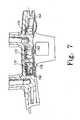
- the exemplary covers 160, 162, and 164 cover openings to plenums 170, 172, and 174 ( FIG. 7 ).
- the plenum 170 (hereinafter a first plenum) is immediately to the pressure side of the first airfoil.
- the plenum 172 (hereinafter a third plenum) is immediately to the suction side of the second airfoil and separated from the first plenum by a dividing wall 176.
- the plenum 174 (hereinafter a fourth plenum) is immediately to the pressure side of the second airfoil.
- these relative positions are characterized when viewed in superposition normal to the airfoil spans.
- the plenums are, however, positioned radially Inward of the adjacent airfoil surfaces.
- each of the plenums 170 and 172 feeds an associated subgroup of the outlet holes 120.
- the plenums may be cast by ceramic cores which may be separately formed from the ceramic feed cores forming the spanwise passageways.
- the holes 120 and their associated outlet passageways 178 (schematically shown in FIG. 6 by their centerlines) from the respective plenums 170 and 172 may be drilled (e.g., via laser drilling or electrodischarge machining (EDM)).
- EDM electrodischarge machining
- the plenum 170 is fed by the first airfoil's spanwise passageways through one or more feed passageways 180.
- the passageways 180 may be cast in place or may be drilled (e.g., in the same step as the outlet passageways 178).
- the plenum 172 is indirectly fed from the second airfoil's spanwise passageways via the plenum 174.
- feed passageways 182 may be drilled from the plenum 174 to the second airfoil's spanwise passageways.
- FIG. 8 also shows the plenums 170 and 172 as being cast with a plurality of heat transfer pedestals 186.
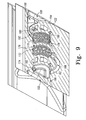
- a connector passageway 188 ( FIG. 9 ) joins the plenums 172 and 174.
- An exemplary connector passageway 188 may be cast in place.
- a single ceramic core is used to cast the plenums 172 and 174 and connector passageway 188.
- the ceramic core and any additional cores may be overmolded with wax to form a pattern.
- previously exposed portions of the ceramic core may become integrated with the shell so as to protrude from an interior surface of the shell that casts the platform inboard surface (of the casting).
- the exemplary connector passageway 188 is positioned to be subsurface to the platform inboard surface (of the casting) whereas the plenums 170, 172, and 174 are exposed to the surface and thus must be closed such as by the covers 160, 162, and 164.
- This exposure facilitates chemical decoring.
- the covers may be welded in place (e.g., first by tack welding for positioning then by a full perimeter welding for sealing and structural integrity).
- the covers 160 and 162 are shaped to have two-point contact on either side of a gap 189. This allows the gap to be aligned with the center of the rib 176 to precisely position the covers and permit the welding.
- the plenum 170 may feed a plenum 190 (hereinafter a second plenum) via a connector passageway 192.
- An exemplary plenum 190 Is positioned among the suction side of the first airfoil near the leading edge thereof.
- the plenums 170, 190, and connector passageway 192 may also be cast by a single ceramic core. This may be the same ceramic core that casts the plenums 172 and 174 and their connector passageway 188 or may be separately formed.
- the exemplary plenum 190 feeds the outlet holes 122 via outlet passageways 194 (shown schematically by their centerlines).
- the exemplary plenum 174 feeds the outlet holes 124 via outlet passageways 196.
- the outlet passageways 194 and 196 may be drilled at the same time as the outlet passageways 178.
- the passageway network of the exemplary cluster may have one or more of several advantageous properties.
- One advantage is that cooling air is introduced to both platform circumferential ends 86 and 88. This may be contrasted with a baseline situation wherein cooling air is introduced to only one of the ends. In such a baseline situation, the cooling air from that end will also serve to cool the adjacent other platform end of the adjacent cluster. However, cooling both ends may increase part life.
- Another possible advantage involves the separate feeding of the plenums 170 and 172.
- the separate feeding of the plenums 170 and 172 reduces the possibilities of adverse interaction between the airflows through the two airfoils. This may be contrasted with a baseline situation wherein a single large plenum between the airfoils is fed with air from both airfoils.
- Such baseline mixing may present engineering problems. For example, it may be desirable to avoid backpressure in the plenum from air flowing from one of the airfoils to interfere with cooling air passing through the other airfoil. Also, the platform area between these plenums and the surface 74 may be subject to different heating considerations.
- the separate feeding may permit a more precise tailoring of airflow properties through each of the sets of passageways 178.
Landscapes
- Engineering & Computer Science (AREA)
- Mechanical Engineering (AREA)
- General Engineering & Computer Science (AREA)
- Turbine Rotor Nozzle Sealing (AREA)
Claims (18)
- Leitschaufel-Cluster (60), aufweisend:eine Plattform (68);einen Mantel (72);mindestens ein erstes und ein zweites Strömungsprofil (62, 64), die sich zwischen einer Außenfläche (74) der Plattform (68) und einer Innenfläche (76) des Mantels (72) erstrecken, wobei jedes Strömungsprofil (62, 64) eine Druckseite und eine Sogseite aufweist, wobei die Druckseite des ersten Strömungsprofils (62) der Sogseite des zweiten Strömungsprofils (64) zugewandt ist, und wobei die Plattform (68), der Mantel (72) und die Strömungsprofile (62, 64) als ein einziges Gussteil ausgebildet sind; undein Kühlpassagensystem, wobei:das Kühlpassagensystem Folgendes aufweist:mindestens einen Einlass (110, 112) in dem Mantel (72);mindestens eine erste Zufuhrpassage von dem Mantel (72) zu der Plattform (68) durch das erste Strömungsprofil (62) hindurch;mindestens eine zweite Zufuhrpassage von dem Mantel (72) zu der Plattform (68) durch das zweite Strömungsprofil (64) hindurch;eine erste Plattformkühlkammer (170) druckseitig von dem ersten Strömungsprofil (62); undeine zweite Plattformkühlkammer (190) sogseitig von dem ersten Strömungsprofil (62);dadurch gekennzeichnet, dass das Kühlpassagensystem ferner Folgendes aufweist:eine erste und eine zweite Mehrzahl von Passagen (194, 196), die sich zu einer ersten bzw. zweiten Mehrzahl von Austrittsöffnungen (122, 124) in einem ersten und einem zweiten umfangsseitigen Ende (86, 88) der Plattform (68) erstrecken.
- Cluster nach Anspruch 1, wobei:die erste Plattformkühlkammer (170) mit der mindestens einen ersten Zufuhrpassage gekoppelt ist; unddie zweite Plattformkühlkammer (190) mit der mindestens einen ersten Zufuhrpassage über die erste Plattformkühlkammer (170) und einen Verbinder (192) gekoppelt ist.
- Cluster nach Anspruch 1 oder Anspruch 2, wobei:eine dritte Plattformkühlkammer (172) sogseitig von dem zweiten Strömungsprofil (64) angeordnet und mit der mindestens einen zweiten Zufuhrpassage gekoppelt ist.
- Verfahren zum Herstellen des Clusters nach Anspruch 1, aufweisend:Herstellen eines Gussteils durch ein Präzisionsgussverfahren, wobei das Gussteil Vorläufer von der Plattform (68), dem Mantel (72), dem ersten und dem zweiten Strömungsprofil (62, 64), der ersten und der zweiten Zufuhrpassage sowie der ersten und der zweiten Plattformkühlkammer (170, 190) beinhaltet; undBefestigen mindestens einer Abdeckung (160) über der ersten Plattformkühlkammer (170).
- Verfahren nach Anspruch 4, wobei:in dem Präzisionsgussverfahren ein erster und ein zweiter Zuführkern verwendet werden, um die erste und die zweiten Zufuhrpassage zu gießen, und ein einzelner separater Kern zum Gießen der ersten und der zweiten Plattformkühlkammer (170, 190) verwendet wird; undin dem Gussteil im gegossenen Zustand der erste Plattformkühlkammer-Vorläufer entlang einer innenseitigen Oberfläche des Plattform-Vorläufers offen ist, jedoch der zweite Plattformkühlkammer-Vorläufer gegenüber der innenseitigen Oberfläche unter dieser Oberfläche angeordnet ist.
- Leitschaufel-Cluster (60) nach Anspruch 1, aufweisend:eine vierte Plattformkühlkammer (174) druckseitig von dem zweiten Strömungsprofil (64).
- Cluster nach Anspruch 6, wobei:sich die Mehrzahl der ersten Austrittspassagen (194) von der zweiten Plattformkühlkammer (190) zu dem ersten Umfangsende (86) der Plattform (68) erstreckt; undsich die Mehrzahl von zweiten Austrittspassagen (196) von der vierten Plattformkühlkammer (174) zu dem zweiten Umfangsende (88) der Plattform (68) erstreckt.
- Cluster nach Anspruch 6 oder 7,
wobei mindestens eine von der ersten Plattformkühlkammer (170) und einer dritten Plattformkühlkammer (172) zwischen dem ersten und dem zweiten Strömungsprofil (62, 64) angeordnet ist. - Cluster nach Anspruch 6 oder 7,
wobei die erste Plattformkühlkammer (170) und eine dritte Plattformkühlkammer (172) zwischen dem ersten und dem zweiten Strömungsprofil (62, 64) angeordnet sind. - Cluster nach Anspruch 9, wobei:eine erste Verbinderpassage (192) in der Plattform (68) derart positioniert ist, dass die zweite Plattformkühlkammer (190) von der ersten Plattformkühlkammer (170) gespeist wird; undeine zweite Verbinderpassage (188) in der Plattform (68) derart positioniert ist, dass die dritte Plattformkühlkammer (172) von der vierten Plattformkühlkammer (174) gespeist wird.
- Cluster nach Anspruch 10, wobei:sich mindestens eine erste Zuführöffnung (180) von der mindestens einen ersten Zufuhrpassage zu der ersten Plattformkühlkammer (170) erstreckt; undsich mindestens eine zweite Zuführöffnung (182) von der mindestens einen zweiten Zufuhrpassage zu der vierten Plattformkühlkammer (174) erstreckt.
- Cluster nach Anspruch 10 oder 11, aufweisend:ein Gussteil, das im Wesentlichen die Strömungsprofile (62, 64) und zumindest Hauptkörperbereiche der Plattform (68) und des Mantels (72) bildet; unddrei Abdeckplatten (164, 160, 162), die mit dem Plattform-Hauptkörperbereich verschweißt sind, um jeweils die vierte, die erste und die dritte Plattformkühlkammer (174, 170, 172) zu umschließen, wobei die zweite Kühlkammer (190) im Inneren des Gussteils angeordnet ist.
- Verfahren zum Herstellen des Clusters nach Anspruch 6, aufweisend:Herstellen eines Gussteils durch ein Präzisionsgussverfahren, wobei das Gussteil Vorläufer von der Plattform (68), dem Mantel (72), dem ersten und dem zweiten Strömungsprofil (62, 64), der ersten und der zweiten Zufuhrpassage sowie der zweiten und der vierten Plattformkühlkammer (190, 174) beinhaltet; undBefestigen mindestens einer Abdeckung (160) über der zweiten und der vierten Plattformkühlkammer (190, 174).
- Verfahren nach Anspruch 13, wobei:in dem Präzisionsgussverfahren ein erster und ein zweiter Zuführkern verwendet werden, um die erste und zweite Zufuhrpassage zu gießen, und mindestens ein separater Kern zum Gießen der zweiten und der vierten Plattformkühlkammer (190, 170) verwendet wird; undin dem Gussteil im gegossenen Zustand der zweite und der vierte Plattformkühlkammer-Vorläufer entlang einer innenseitigen Oberfläche des Plattform-Vorläufers offen sind.
- Leitschaufel-Cluster (60) nach Anspruch 1,
wobei das Kühlpassagensystem aufweist:eine vierte Plattformkühlkammer (174) druckseitig von dem zweiten Strömungsprofil (64); undeine dritte Plattformkühlkammer (172) sogseitig von dem zweiten Strömungsprofil (64); undeine Verbinderpassage (188), die die vierte Plattformkühlkammer (174) mit der dritten Plattformkühlkammer (172) verbindet. - Cluster nach Anspruch 15, wobei:sich die zweite Mehrzahl von Passagen (196) von der vierten Plattformkühlkammer (174) zu dem benachbarten Umfangsende (88) der Plattform (68) erstreckt; undsich die Verbinderpassage (188) um einen hinteren Rand des zweiten Strömungsprofils (64) herum erstreckt.
- Verfahren zum Herstellen des Clusters nach Anspruch 15, aufweisend:Herstellen eines Gussteils durch ein Präzisionsgussverfahren, wobei das Gussteil Vorläufer von der Plattform (68), dem Mantel (72), dem ersten und dem zweiten Strömungsprofil (62, 64), der ersten und der zweiten Zufuhrpassage sowie der dritten und der vierten Plattformkühlkammer (172, 174) beinhaltet; undBefestigen mindestens einer Abdeckung (164, 162) über der dritten und der vierten Plattformkühlkammer (172, 174).
- Verfahren nach Anspruch 17, wobei:in dem Präzisionsgussverfahren ein erster und ein zweiter Zuführkern verwendet werden, um die erste und die zweiten Zufuhrpassage zu gießen, und mindestens ein separater Kern zum Gießen der dritten und vierten Plattformkühlkammer (172, 174) verwendet wird; undin dem Gussteil im gegossenen Zustand der dritte und der vierte Plattformkühlkammer-Vorläufer entlang einer innenseitigen Oberfläche des Plattform-Vorläufers offen sind und die Verbinderpassage (188) unter der Oberfläche angeordnet ist.
Applications Claiming Priority (1)
| Application Number | Priority Date | Filing Date | Title |
|---|---|---|---|
| US11/412,291 US7625172B2 (en) | 2006-04-26 | 2006-04-26 | Vane platform cooling |
Publications (3)
| Publication Number | Publication Date |
|---|---|
| EP1849965A2 EP1849965A2 (de) | 2007-10-31 |
| EP1849965A3 EP1849965A3 (de) | 2011-05-18 |
| EP1849965B1 true EP1849965B1 (de) | 2015-02-18 |
Family
ID=37930370
Family Applications (1)
| Application Number | Title | Priority Date | Filing Date |
|---|---|---|---|
| EP07250726.2A Active EP1849965B1 (de) | 2006-04-26 | 2007-02-21 | Kühlung der Plattform einer Leitschaufel |
Country Status (4)
| Country | Link |
|---|---|
| US (1) | US7625172B2 (de) |
| EP (1) | EP1849965B1 (de) |
| JP (1) | JP2007292052A (de) |
| CN (1) | CN101063411A (de) |
Cited By (13)
| Publication number | Priority date | Publication date | Assignee | Title |
|---|---|---|---|---|
| US9579714B1 (en) | 2015-12-17 | 2017-02-28 | General Electric Company | Method and assembly for forming components having internal passages using a lattice structure |
| US9968991B2 (en) | 2015-12-17 | 2018-05-15 | General Electric Company | Method and assembly for forming components having internal passages using a lattice structure |
| US9987677B2 (en) | 2015-12-17 | 2018-06-05 | General Electric Company | Method and assembly for forming components having internal passages using a jacketed core |
| US10046389B2 (en) | 2015-12-17 | 2018-08-14 | General Electric Company | Method and assembly for forming components having internal passages using a jacketed core |
| US10099283B2 (en) | 2015-12-17 | 2018-10-16 | General Electric Company | Method and assembly for forming components having an internal passage defined therein |
| US10099284B2 (en) | 2015-12-17 | 2018-10-16 | General Electric Company | Method and assembly for forming components having a catalyzed internal passage defined therein |
| US10099276B2 (en) | 2015-12-17 | 2018-10-16 | General Electric Company | Method and assembly for forming components having an internal passage defined therein |
| US10118217B2 (en) | 2015-12-17 | 2018-11-06 | General Electric Company | Method and assembly for forming components having internal passages using a jacketed core |
| US10137499B2 (en) | 2015-12-17 | 2018-11-27 | General Electric Company | Method and assembly for forming components having an internal passage defined therein |
| US10150158B2 (en) | 2015-12-17 | 2018-12-11 | General Electric Company | Method and assembly for forming components having internal passages using a jacketed core |
| US10286450B2 (en) | 2016-04-27 | 2019-05-14 | General Electric Company | Method and assembly for forming components using a jacketed core |
| US10335853B2 (en) | 2016-04-27 | 2019-07-02 | General Electric Company | Method and assembly for forming components using a jacketed core |
| US10907481B2 (en) | 2013-09-17 | 2021-02-02 | Raytheon Technologies Corporation | Platform cooling core for a gas turbine engine rotor blade |
Families Citing this family (45)
| Publication number | Priority date | Publication date | Assignee | Title |
|---|---|---|---|---|
| US8133015B2 (en) * | 2008-09-30 | 2012-03-13 | General Electric Company | Turbine nozzle for a gas turbine engine |
| US8353669B2 (en) * | 2009-08-18 | 2013-01-15 | United Technologies Corporation | Turbine vane platform leading edge cooling holes |
| DE102010005153A1 (de) | 2010-01-21 | 2011-07-28 | MTU Aero Engines GmbH, 80995 | Gehäusesystem für eine Axialströmungsmaschine |
| US8371800B2 (en) * | 2010-03-03 | 2013-02-12 | General Electric Company | Cooling gas turbine components with seal slot channels |
| US8356975B2 (en) * | 2010-03-23 | 2013-01-22 | United Technologies Corporation | Gas turbine engine with non-axisymmetric surface contoured vane platform |
| US9976433B2 (en) | 2010-04-02 | 2018-05-22 | United Technologies Corporation | Gas turbine engine with non-axisymmetric surface contoured rotor blade platform |
| US20120177479A1 (en) * | 2011-01-06 | 2012-07-12 | Gm Salam Azad | Inner shroud cooling arrangement in a gas turbine engine |
| RU2536443C2 (ru) * | 2011-07-01 | 2014-12-27 | Альстом Текнолоджи Лтд | Направляющая лопатка турбины |
| JP5881369B2 (ja) * | 2011-10-27 | 2016-03-09 | 三菱重工業株式会社 | タービン動翼及びこれを備えたガスタービン |
| US9022735B2 (en) * | 2011-11-08 | 2015-05-05 | General Electric Company | Turbomachine component and method of connecting cooling circuits of a turbomachine component |
| US10180067B2 (en) | 2012-05-31 | 2019-01-15 | United Technologies Corporation | Mate face cooling holes for gas turbine engine component |
| BR112014031269A2 (pt) * | 2012-06-15 | 2017-08-08 | Gen Electric | aparelho de aerofólio de turbina e método de formação de um padrão de orifício de resfriamento. |
| US9021816B2 (en) * | 2012-07-02 | 2015-05-05 | United Technologies Corporation | Gas turbine engine turbine vane platform core |
| US9334756B2 (en) | 2012-09-28 | 2016-05-10 | United Technologies Corporation | Liner and method of assembly |
| US9080452B2 (en) | 2012-09-28 | 2015-07-14 | United Technologies Corporation | Gas turbine engine airfoil with vane platform cooling passage |
| EP2956627B1 (de) | 2013-02-15 | 2018-07-25 | United Technologies Corporation | Gasturbinenmotorkomponente mit kombinierter anpassungsfläche und plattformkühlung |
| EP4019754B1 (de) | 2013-03-15 | 2026-03-11 | RTX Corporation | Akustische auskleidung mit unterschiedlichen eigenschaften |
| EP3036405B1 (de) | 2013-08-20 | 2021-05-12 | Raytheon Technologies Corporation | Gasturbinenkomponente, gasturbine mit einer solchen komponente und verfahren zur kühlung einer gasturbinenkomponente |
| US9562439B2 (en) * | 2013-12-27 | 2017-02-07 | General Electric Company | Turbine nozzle and method for cooling a turbine nozzle of a gas turbine engine |
| US10041374B2 (en) | 2014-04-04 | 2018-08-07 | United Technologies Corporation | Gas turbine engine component with platform cooling circuit |
| US9771816B2 (en) | 2014-05-07 | 2017-09-26 | General Electric Company | Blade cooling circuit feed duct, exhaust duct, and related cooling structure |
| US9638045B2 (en) | 2014-05-28 | 2017-05-02 | General Electric Company | Cooling structure for stationary blade |
| US10689988B2 (en) | 2014-06-12 | 2020-06-23 | Raytheon Technologies Corporation | Disk lug impingement for gas turbine engine airfoil |
| US9988916B2 (en) | 2015-07-16 | 2018-06-05 | General Electric Company | Cooling structure for stationary blade |
| US9909436B2 (en) | 2015-07-16 | 2018-03-06 | General Electric Company | Cooling structure for stationary blade |
| US9822653B2 (en) | 2015-07-16 | 2017-11-21 | General Electric Company | Cooling structure for stationary blade |
| JP6540357B2 (ja) | 2015-08-11 | 2019-07-10 | 三菱日立パワーシステムズ株式会社 | 静翼、及びこれを備えているガスタービン |
| US10436042B2 (en) | 2015-12-01 | 2019-10-08 | United Technologies Corporation | Thermal barrier coatings and methods |
| CN105673089B (zh) * | 2016-03-31 | 2018-06-29 | 中国船舶重工集团公司第七�三研究所 | 一种燃气轮机涡轮无冠气膜冷却转子叶片 |
| GB201612646D0 (en) * | 2016-07-21 | 2016-09-07 | Rolls Royce Plc | An air cooled component for a gas turbine engine |
| EP3287596A1 (de) * | 2016-08-25 | 2018-02-28 | Siemens Aktiengesellschaft | Plattformkühlungsvorrichtung für eine schaufel einer turbomaschine und turbomaschinenanordnung |
| US20190071978A1 (en) * | 2017-09-01 | 2019-03-07 | United Technologies Corporation | Turbine vane cluster including enhanced platform cooling |
| US20190085706A1 (en) * | 2017-09-18 | 2019-03-21 | General Electric Company | Turbine engine airfoil assembly |
| US11118474B2 (en) | 2017-10-09 | 2021-09-14 | Raytheon Technologies Corporation | Vane cooling structures |
| US10612406B2 (en) | 2018-04-19 | 2020-04-07 | United Technologies Corporation | Seal assembly with shield for gas turbine engines |
| US10989067B2 (en) * | 2018-07-13 | 2021-04-27 | Honeywell International Inc. | Turbine vane with dust tolerant cooling system |
| US11180998B2 (en) | 2018-11-09 | 2021-11-23 | Raytheon Technologies Corporation | Airfoil with skincore passage resupply |
| US11156116B2 (en) * | 2019-04-08 | 2021-10-26 | Honeywell International Inc. | Turbine nozzle with reduced leakage feather seals |
| US11021966B2 (en) * | 2019-04-24 | 2021-06-01 | Raytheon Technologies Corporation | Vane core assemblies and methods |
| US11220924B2 (en) | 2019-09-26 | 2022-01-11 | Raytheon Technologies Corporation | Double box composite seal assembly with insert for gas turbine engine |
| US11359507B2 (en) | 2019-09-26 | 2022-06-14 | Raytheon Technologies Corporation | Double box composite seal assembly with fiber density arrangement for gas turbine engine |
| US11352897B2 (en) | 2019-09-26 | 2022-06-07 | Raytheon Technologies Corporation | Double box composite seal assembly for gas turbine engine |
| US11230929B2 (en) | 2019-11-05 | 2022-01-25 | Honeywell International Inc. | Turbine component with dust tolerant cooling system |
| US11459895B2 (en) * | 2020-04-14 | 2022-10-04 | Raytheon Technologies Corporation | Turbine blade cooling hole for side wall |
| CN112282860A (zh) * | 2020-11-17 | 2021-01-29 | 西安热工研究院有限公司 | 一种涡轮转子叶片平台冷却结构 |
Family Cites Families (13)
| Publication number | Priority date | Publication date | Assignee | Title |
|---|---|---|---|---|
| US4353679A (en) * | 1976-07-29 | 1982-10-12 | General Electric Company | Fluid-cooled element |
| US4218178A (en) * | 1978-03-31 | 1980-08-19 | General Motors Corporation | Turbine vane structure |
| FR2723144B1 (fr) * | 1984-11-29 | 1996-12-13 | Snecma | Distributeur de turbine |
| JPH0552102A (ja) * | 1991-08-23 | 1993-03-02 | Toshiba Corp | ガスタービン |
| US5344283A (en) | 1993-01-21 | 1994-09-06 | United Technologies Corporation | Turbine vane having dedicated inner platform cooling |
| US5413458A (en) | 1994-03-29 | 1995-05-09 | United Technologies Corporation | Turbine vane with a platform cavity having a double feed for cooling fluid |
| US5634766A (en) * | 1994-08-23 | 1997-06-03 | General Electric Co. | Turbine stator vane segments having combined air and steam cooling circuits |
| JP3495554B2 (ja) * | 1997-04-24 | 2004-02-09 | 三菱重工業株式会社 | ガスタービン静翼の冷却シュラウド |
| US6065928A (en) * | 1998-07-22 | 2000-05-23 | General Electric Company | Turbine nozzle having purge air circuit |
| DE10016081A1 (de) * | 2000-03-31 | 2001-10-04 | Alstom Power Nv | Plattenförmiger, auskragender Bauteilabschnitt einer Gasturbine |
| JP4508482B2 (ja) * | 2001-07-11 | 2010-07-21 | 三菱重工業株式会社 | ガスタービン静翼 |
| US6945749B2 (en) * | 2003-09-12 | 2005-09-20 | Siemens Westinghouse Power Corporation | Turbine blade platform cooling system |
| US20050135923A1 (en) * | 2003-12-22 | 2005-06-23 | Todd Coons | Cooled vane cluster |
-
2006
- 2006-04-26 US US11/412,291 patent/US7625172B2/en active Active
-
2007
- 2007-02-21 EP EP07250726.2A patent/EP1849965B1/de active Active
- 2007-02-23 JP JP2007043116A patent/JP2007292052A/ja active Pending
- 2007-02-25 CN CNA2007100058036A patent/CN101063411A/zh active Pending
Cited By (14)
| Publication number | Priority date | Publication date | Assignee | Title |
|---|---|---|---|---|
| US10907481B2 (en) | 2013-09-17 | 2021-02-02 | Raytheon Technologies Corporation | Platform cooling core for a gas turbine engine rotor blade |
| US10099284B2 (en) | 2015-12-17 | 2018-10-16 | General Electric Company | Method and assembly for forming components having a catalyzed internal passage defined therein |
| US9975176B2 (en) | 2015-12-17 | 2018-05-22 | General Electric Company | Method and assembly for forming components having internal passages using a lattice structure |
| US9987677B2 (en) | 2015-12-17 | 2018-06-05 | General Electric Company | Method and assembly for forming components having internal passages using a jacketed core |
| US10046389B2 (en) | 2015-12-17 | 2018-08-14 | General Electric Company | Method and assembly for forming components having internal passages using a jacketed core |
| US10099283B2 (en) | 2015-12-17 | 2018-10-16 | General Electric Company | Method and assembly for forming components having an internal passage defined therein |
| US9579714B1 (en) | 2015-12-17 | 2017-02-28 | General Electric Company | Method and assembly for forming components having internal passages using a lattice structure |
| US10099276B2 (en) | 2015-12-17 | 2018-10-16 | General Electric Company | Method and assembly for forming components having an internal passage defined therein |
| US10118217B2 (en) | 2015-12-17 | 2018-11-06 | General Electric Company | Method and assembly for forming components having internal passages using a jacketed core |
| US10137499B2 (en) | 2015-12-17 | 2018-11-27 | General Electric Company | Method and assembly for forming components having an internal passage defined therein |
| US10150158B2 (en) | 2015-12-17 | 2018-12-11 | General Electric Company | Method and assembly for forming components having internal passages using a jacketed core |
| US9968991B2 (en) | 2015-12-17 | 2018-05-15 | General Electric Company | Method and assembly for forming components having internal passages using a lattice structure |
| US10286450B2 (en) | 2016-04-27 | 2019-05-14 | General Electric Company | Method and assembly for forming components using a jacketed core |
| US10335853B2 (en) | 2016-04-27 | 2019-07-02 | General Electric Company | Method and assembly for forming components using a jacketed core |
Also Published As
| Publication number | Publication date |
|---|---|
| CN101063411A (zh) | 2007-10-31 |
| US7625172B2 (en) | 2009-12-01 |
| US20070253816A1 (en) | 2007-11-01 |
| JP2007292052A (ja) | 2007-11-08 |
| EP1849965A3 (de) | 2011-05-18 |
| EP1849965A2 (de) | 2007-10-31 |
Similar Documents
| Publication | Publication Date | Title |
|---|---|---|
| EP1849965B1 (de) | Kühlung der Plattform einer Leitschaufel | |
| EP1813775B1 (de) | Filmgekühlte Bauteile einer Gasturbine | |
| EP1916388B1 (de) | Schaufel mit erhöhter Wärmeübertragung | |
| US8206108B2 (en) | Turbine blades and methods of manufacturing | |
| US10196917B2 (en) | Blade outer air seal with cored passages | |
| JP4658584B2 (ja) | 内側寄り冷却式ノズルダブレット | |
| EP3034808B1 (de) | Gusskern für eine schaufelaussendichtung, schaufelaussendichtung und entsprechendes fertigungsverfahren | |
| US8414263B1 (en) | Turbine stator vane with near wall integrated micro cooling channels | |
| US7625178B2 (en) | High effectiveness cooled turbine blade | |
| EP3556999B1 (de) | Doppelwandige schaufelkühlkonfiguration für gasturbinenmotoren | |
| US10247015B2 (en) | Cooled blisk with dual wall blades for gas turbine engine | |
| US10415403B2 (en) | Cooled blisk for gas turbine engine | |
| EP1801351A2 (de) | Kühlung für eine Turbinenschaufelspitze | |
| US10184353B2 (en) | Blade outer air seal cooling scheme | |
| KR20170122676A (ko) | 재킷식 코어를 사용하여 구성요소를 형성하는 방법 및 조립체 | |
| EP3508691B1 (de) | Verfahren zur herstellung eines kühlkanals für eine turbinenkomponente mit abdeckelement | |
| EP3730742B1 (de) | Gasturbine und verfahren zur herstellung | |
| US10024190B1 (en) | Apparatus and process for forming an air cooled turbine airfoil with a cooling air channel and discharge slot in a thin wall | |
| EP4450761A1 (de) | Schaufelbauteil, gasturbinentriebwerk, verfahren zum herstellen eines schaufelbauteils, verfahren zum verwenden eines schaufelbauteils, schaufelbauteil und gusskernanordnung zum giessen eines schaufelbauteil | |
| US12497896B2 (en) | Airfoil assembly with platform film holes | |
| EP4428338A2 (de) | Turbinenschaufeln eines turbinenmotors mit filmkühlung und herstellungsverfahren |
Legal Events
| Date | Code | Title | Description |
|---|---|---|---|
| PUAI | Public reference made under article 153(3) epc to a published international application that has entered the european phase |
Free format text: ORIGINAL CODE: 0009012 |
|
| AK | Designated contracting states |
Kind code of ref document: A2 Designated state(s): AT BE BG CH CY CZ DE DK EE ES FI FR GB GR HU IE IS IT LI LT LU LV MC NL PL PT RO SE SI SK TR |
|
| AX | Request for extension of the european patent |
Extension state: AL BA HR MK YU |
|
| PUAL | Search report despatched |
Free format text: ORIGINAL CODE: 0009013 |
|
| AK | Designated contracting states |
Kind code of ref document: A3 Designated state(s): AT BE BG CH CY CZ DE DK EE ES FI FR GB GR HU IE IS IT LI LT LU LV MC NL PL PT RO SE SI SK TR |
|
| AX | Request for extension of the european patent |
Extension state: AL BA HR MK RS |
|
| 17P | Request for examination filed |
Effective date: 20111115 |
|
| AKX | Designation fees paid |
Designated state(s): DE FR GB IT |
|
| 17Q | First examination report despatched |
Effective date: 20120214 |
|
| GRAP | Despatch of communication of intention to grant a patent |
Free format text: ORIGINAL CODE: EPIDOSNIGR1 |
|
| INTG | Intention to grant announced |
Effective date: 20140812 |
|
| GRAS | Grant fee paid |
Free format text: ORIGINAL CODE: EPIDOSNIGR3 |
|
| GRAA | (expected) grant |
Free format text: ORIGINAL CODE: 0009210 |
|
| AK | Designated contracting states |
Kind code of ref document: B1 Designated state(s): DE FR GB IT |
|
| REG | Reference to a national code |
Ref country code: GB Ref legal event code: FG4D |
|
| REG | Reference to a national code |
Ref country code: DE Ref legal event code: R081 Ref document number: 602007040256 Country of ref document: DE Owner name: UNITED TECHNOLOGIES CORP. (N.D.GES.D. STAATES , US Free format text: FORMER OWNER: UNITED TECHNOLOGIES INC., HARTFORD, CONN., US |
|
| REG | Reference to a national code |
Ref country code: DE Ref legal event code: R096 Ref document number: 602007040256 Country of ref document: DE Effective date: 20150402 |
|
| PGFP | Annual fee paid to national office [announced via postgrant information from national office to epo] |
Ref country code: IT Payment date: 20150326 Year of fee payment: 9 |
|
| REG | Reference to a national code |
Ref country code: DE Ref legal event code: R097 Ref document number: 602007040256 Country of ref document: DE |
|
| PLBE | No opposition filed within time limit |
Free format text: ORIGINAL CODE: 0009261 |
|
| STAA | Information on the status of an ep patent application or granted ep patent |
Free format text: STATUS: NO OPPOSITION FILED WITHIN TIME LIMIT |
|
| REG | Reference to a national code |
Ref country code: FR Ref legal event code: PLFP Year of fee payment: 10 |
|
| 26N | No opposition filed |
Effective date: 20151119 |
|
| PG25 | Lapsed in a contracting state [announced via postgrant information from national office to epo] |
Ref country code: IT Free format text: LAPSE BECAUSE OF NON-PAYMENT OF DUE FEES Effective date: 20160221 |
|
| REG | Reference to a national code |
Ref country code: FR Ref legal event code: PLFP Year of fee payment: 11 |
|
| REG | Reference to a national code |
Ref country code: FR Ref legal event code: CA Effective date: 20170324 |
|
| REG | Reference to a national code |
Ref country code: DE Ref legal event code: R082 Ref document number: 602007040256 Country of ref document: DE Representative=s name: SCHMITT-NILSON SCHRAUD WAIBEL WOHLFROM PATENTA, DE |
|
| REG | Reference to a national code |
Ref country code: DE Ref legal event code: R082 Ref document number: 602007040256 Country of ref document: DE Representative=s name: SCHMITT-NILSON SCHRAUD WAIBEL WOHLFROM PATENTA, DE Ref country code: DE Ref legal event code: R081 Ref document number: 602007040256 Country of ref document: DE Owner name: UNITED TECHNOLOGIES CORP. (N.D.GES.D. STAATES , US Free format text: FORMER OWNER: UNITED TECHNOLOGIES CORPORATION, HARTFORD, CONN., US |
|
| REG | Reference to a national code |
Ref country code: FR Ref legal event code: PLFP Year of fee payment: 12 |
|
| REG | Reference to a national code |
Ref country code: DE Ref legal event code: R081 Ref document number: 602007040256 Country of ref document: DE Owner name: RAYTHEON TECHNOLOGIES CORPORATION (N.D.GES.D.S, US Free format text: FORMER OWNER: UNITED TECHNOLOGIES CORP. (N.D.GES.D. STAATES DELAWARE), FARMINGTON, CONN., US Ref country code: DE Ref legal event code: R081 Ref document number: 602007040256 Country of ref document: DE Owner name: RTX CORPORATION (N.D.GES.D. STAATES DELAWARE),, US Free format text: FORMER OWNER: UNITED TECHNOLOGIES CORP. (N.D.GES.D. STAATES DELAWARE), FARMINGTON, CONN., US |
|
| P01 | Opt-out of the competence of the unified patent court (upc) registered |
Effective date: 20230519 |
|
| PGFP | Annual fee paid to national office [announced via postgrant information from national office to epo] |
Ref country code: DE Payment date: 20250122 Year of fee payment: 19 |
|
| PGFP | Annual fee paid to national office [announced via postgrant information from national office to epo] |
Ref country code: FR Payment date: 20250122 Year of fee payment: 19 |
|
| PGFP | Annual fee paid to national office [announced via postgrant information from national office to epo] |
Ref country code: GB Payment date: 20250123 Year of fee payment: 19 |
|
| REG | Reference to a national code |
Ref country code: DE Ref legal event code: R081 Ref document number: 602007040256 Country of ref document: DE Owner name: RTX CORPORATION (N.D.GES.D. STAATES DELAWARE),, US Free format text: FORMER OWNER: RAYTHEON TECHNOLOGIES CORPORATION (N.D.GES.D.STAATES DELAWARE), ARLINGTON, VA, US |