EP1850941B1 - Filtervorrichtung - Google Patents
Filtervorrichtung Download PDFInfo
- Publication number
- EP1850941B1 EP1850941B1 EP06735607A EP06735607A EP1850941B1 EP 1850941 B1 EP1850941 B1 EP 1850941B1 EP 06735607 A EP06735607 A EP 06735607A EP 06735607 A EP06735607 A EP 06735607A EP 1850941 B1 EP1850941 B1 EP 1850941B1
- Authority
- EP
- European Patent Office
- Prior art keywords
- filter
- filter element
- housing
- valve
- keys
- Prior art date
- Legal status (The legal status is an assumption and is not a legal conclusion. Google has not performed a legal analysis and makes no representation as to the accuracy of the status listed.)
- Expired - Lifetime
Links
Images



















Classifications
-
- B—PERFORMING OPERATIONS; TRANSPORTING
- B01—PHYSICAL OR CHEMICAL PROCESSES OR APPARATUS IN GENERAL
- B01D—SEPARATION
- B01D29/00—Filters with filtering elements stationary during filtration, e.g. pressure or suction filters, not covered by groups B01D24/00 - B01D27/00; Filtering elements therefor
- B01D29/11—Filters with filtering elements stationary during filtration, e.g. pressure or suction filters, not covered by groups B01D24/00 - B01D27/00; Filtering elements therefor with bag, cage, hose, tube, sleeve or like filtering elements
- B01D29/117—Filters with filtering elements stationary during filtration, e.g. pressure or suction filters, not covered by groups B01D24/00 - B01D27/00; Filtering elements therefor with bag, cage, hose, tube, sleeve or like filtering elements arranged for outward flow filtration
- B01D29/118—Filters with filtering elements stationary during filtration, e.g. pressure or suction filters, not covered by groups B01D24/00 - B01D27/00; Filtering elements therefor with bag, cage, hose, tube, sleeve or like filtering elements arranged for outward flow filtration open-ended
-
- B—PERFORMING OPERATIONS; TRANSPORTING
- B01—PHYSICAL OR CHEMICAL PROCESSES OR APPARATUS IN GENERAL
- B01D—SEPARATION
- B01D29/00—Filters with filtering elements stationary during filtration, e.g. pressure or suction filters, not covered by groups B01D24/00 - B01D27/00; Filtering elements therefor
- B01D29/11—Filters with filtering elements stationary during filtration, e.g. pressure or suction filters, not covered by groups B01D24/00 - B01D27/00; Filtering elements therefor with bag, cage, hose, tube, sleeve or like filtering elements
- B01D29/13—Supported filter elements
- B01D29/15—Supported filter elements arranged for inward flow filtration
- B01D29/21—Supported filter elements arranged for inward flow filtration with corrugated, folded or wound sheets
-
- B—PERFORMING OPERATIONS; TRANSPORTING
- B01—PHYSICAL OR CHEMICAL PROCESSES OR APPARATUS IN GENERAL
- B01D—SEPARATION
- B01D29/00—Filters with filtering elements stationary during filtration, e.g. pressure or suction filters, not covered by groups B01D24/00 - B01D27/00; Filtering elements therefor
- B01D29/11—Filters with filtering elements stationary during filtration, e.g. pressure or suction filters, not covered by groups B01D24/00 - B01D27/00; Filtering elements therefor with bag, cage, hose, tube, sleeve or like filtering elements
- B01D29/13—Supported filter elements
- B01D29/23—Supported filter elements arranged for outward flow filtration
- B01D29/232—Supported filter elements arranged for outward flow filtration with corrugated, folded or wound sheets
-
- B—PERFORMING OPERATIONS; TRANSPORTING
- B01—PHYSICAL OR CHEMICAL PROCESSES OR APPARATUS IN GENERAL
- B01D—SEPARATION
- B01D29/00—Filters with filtering elements stationary during filtration, e.g. pressure or suction filters, not covered by groups B01D24/00 - B01D27/00; Filtering elements therefor
- B01D29/50—Filters with filtering elements stationary during filtration, e.g. pressure or suction filters, not covered by groups B01D24/00 - B01D27/00; Filtering elements therefor with multiple filtering elements, characterised by their mutual disposition
- B01D29/52—Filters with filtering elements stationary during filtration, e.g. pressure or suction filters, not covered by groups B01D24/00 - B01D27/00; Filtering elements therefor with multiple filtering elements, characterised by their mutual disposition in parallel connection
- B01D29/54—Filters with filtering elements stationary during filtration, e.g. pressure or suction filters, not covered by groups B01D24/00 - B01D27/00; Filtering elements therefor with multiple filtering elements, characterised by their mutual disposition in parallel connection arranged concentrically or coaxially
-
- B—PERFORMING OPERATIONS; TRANSPORTING
- B01—PHYSICAL OR CHEMICAL PROCESSES OR APPARATUS IN GENERAL
- B01D—SEPARATION
- B01D35/00—Filtering devices having features not specifically covered by groups B01D24/00 - B01D33/00, or for applications not specifically covered by groups B01D24/00 - B01D33/00; Auxiliary devices for filtration; Filter housing constructions
- B01D35/14—Safety devices specially adapted for filtration; Devices for indicating clogging
- B01D35/147—Bypass or safety valves
-
- B—PERFORMING OPERATIONS; TRANSPORTING
- B01—PHYSICAL OR CHEMICAL PROCESSES OR APPARATUS IN GENERAL
- B01D—SEPARATION
- B01D35/00—Filtering devices having features not specifically covered by groups B01D24/00 - B01D33/00, or for applications not specifically covered by groups B01D24/00 - B01D33/00; Auxiliary devices for filtration; Filter housing constructions
- B01D35/14—Safety devices specially adapted for filtration; Devices for indicating clogging
- B01D35/153—Anti-leakage or anti-return valves
-
- B—PERFORMING OPERATIONS; TRANSPORTING
- B01—PHYSICAL OR CHEMICAL PROCESSES OR APPARATUS IN GENERAL
- B01D—SEPARATION
- B01D35/00—Filtering devices having features not specifically covered by groups B01D24/00 - B01D33/00, or for applications not specifically covered by groups B01D24/00 - B01D33/00; Auxiliary devices for filtration; Filter housing constructions
- B01D35/16—Cleaning-out devices, e.g. for removing the cake from the filter casing or for evacuating the last remnants of liquid
-
- B—PERFORMING OPERATIONS; TRANSPORTING
- B01—PHYSICAL OR CHEMICAL PROCESSES OR APPARATUS IN GENERAL
- B01D—SEPARATION
- B01D36/00—Filter circuits or combinations of filters with other separating devices
- B01D36/003—Filters in combination with devices for the removal of liquids
-
- B—PERFORMING OPERATIONS; TRANSPORTING
- B01—PHYSICAL OR CHEMICAL PROCESSES OR APPARATUS IN GENERAL
- B01D—SEPARATION
- B01D37/00—Processes of filtration
- B01D37/02—Precoating the filter medium; Addition of filter aids to the liquid being filtered
- B01D37/025—Precoating the filter medium; Addition of filter aids to the liquid being filtered additives incorporated in the filter
-
- B—PERFORMING OPERATIONS; TRANSPORTING
- B01—PHYSICAL OR CHEMICAL PROCESSES OR APPARATUS IN GENERAL
- B01D—SEPARATION
- B01D2201/00—Details relating to filtering apparatus
- B01D2201/04—Supports for the filtering elements
- B01D2201/0407—Perforated supports on both sides of the filtering element
-
- B—PERFORMING OPERATIONS; TRANSPORTING
- B01—PHYSICAL OR CHEMICAL PROCESSES OR APPARATUS IN GENERAL
- B01D—SEPARATION
- B01D2201/00—Details relating to filtering apparatus
- B01D2201/04—Supports for the filtering elements
- B01D2201/0415—Details of supporting structures
-
- B—PERFORMING OPERATIONS; TRANSPORTING
- B01—PHYSICAL OR CHEMICAL PROCESSES OR APPARATUS IN GENERAL
- B01D—SEPARATION
- B01D2201/00—Details relating to filtering apparatus
- B01D2201/12—Pleated filters
-
- B—PERFORMING OPERATIONS; TRANSPORTING
- B01—PHYSICAL OR CHEMICAL PROCESSES OR APPARATUS IN GENERAL
- B01D—SEPARATION
- B01D2201/00—Details relating to filtering apparatus
- B01D2201/12—Pleated filters
- B01D2201/127—Pleated filters with means for keeping the spacing between the pleats
-
- B—PERFORMING OPERATIONS; TRANSPORTING
- B01—PHYSICAL OR CHEMICAL PROCESSES OR APPARATUS IN GENERAL
- B01D—SEPARATION
- B01D2201/00—Details relating to filtering apparatus
- B01D2201/28—Position of the filtering element
-
- B—PERFORMING OPERATIONS; TRANSPORTING
- B01—PHYSICAL OR CHEMICAL PROCESSES OR APPARATUS IN GENERAL
- B01D—SEPARATION
- B01D2201/00—Details relating to filtering apparatus
- B01D2201/29—Filter cartridge constructions
- B01D2201/291—End caps
- B01D2201/295—End caps with projections extending in a radial outward direction, e.g. for use as a guide, spacing means
-
- B—PERFORMING OPERATIONS; TRANSPORTING
- B01—PHYSICAL OR CHEMICAL PROCESSES OR APPARATUS IN GENERAL
- B01D—SEPARATION
- B01D2201/00—Details relating to filtering apparatus
- B01D2201/30—Filter housing constructions
- B01D2201/301—Details of removable closures, lids, caps, filter heads
- B01D2201/305—Snap, latch or clip connecting means
-
- B—PERFORMING OPERATIONS; TRANSPORTING
- B01—PHYSICAL OR CHEMICAL PROCESSES OR APPARATUS IN GENERAL
- B01D—SEPARATION
- B01D2201/00—Details relating to filtering apparatus
- B01D2201/40—Special measures for connecting different parts of the filter
-
- B—PERFORMING OPERATIONS; TRANSPORTING
- B01—PHYSICAL OR CHEMICAL PROCESSES OR APPARATUS IN GENERAL
- B01D—SEPARATION
- B01D2201/00—Details relating to filtering apparatus
- B01D2201/40—Special measures for connecting different parts of the filter
- B01D2201/4015—Bayonet connecting means
-
- B—PERFORMING OPERATIONS; TRANSPORTING
- B01—PHYSICAL OR CHEMICAL PROCESSES OR APPARATUS IN GENERAL
- B01D—SEPARATION
- B01D2201/00—Details relating to filtering apparatus
- B01D2201/40—Special measures for connecting different parts of the filter
- B01D2201/4046—Means for avoiding false mounting of different parts
-
- B—PERFORMING OPERATIONS; TRANSPORTING
- B01—PHYSICAL OR CHEMICAL PROCESSES OR APPARATUS IN GENERAL
- B01D—SEPARATION
- B01D2201/00—Details relating to filtering apparatus
- B01D2201/40—Special measures for connecting different parts of the filter
- B01D2201/4084—Snap or Seeger ring connecting means
-
- B—PERFORMING OPERATIONS; TRANSPORTING
- B01—PHYSICAL OR CHEMICAL PROCESSES OR APPARATUS IN GENERAL
- B01D—SEPARATION
- B01D2201/00—Details relating to filtering apparatus
- B01D2201/52—Filter identification means
-
- B—PERFORMING OPERATIONS; TRANSPORTING
- B01—PHYSICAL OR CHEMICAL PROCESSES OR APPARATUS IN GENERAL
- B01D—SEPARATION
- B01D2201/00—Details relating to filtering apparatus
- B01D2201/60—Shape of non-cylindrical filtering elements
Definitions
- This invention relates generally to filtering and separating liquids, and more particularly to filter apparatuses of the type used for the fuel supply of an engine or for the lubrication system of an engine.
- the fuel supply system for an engine will typically include a fuel filter apparatus for removing particulate matter from the fuel before it is supplied to the engine.
- a fuel filter apparatus for removing particulate matter from the fuel before it is supplied to the engine.
- Such filter apparatuses also sometimes include provisions for removing water from the fuel, pre-heating the fuel, and provisions for injecting anti-gel or lubricity additives.
- Such filter apparatuses may also include other devices such as thermostats, pressure sensors, or water sensors.
- the filter may also be required to perform additional functions to neutralize acids or oxidants in the fuel.
- a filter apparatus may be used for the lubrication system of an engine.
- Such filters typically include a filter element for trapping the particulate matter in a media.
- the element is configured so that it can be removed and replaced periodically as it becomes plugged with particulate matter.
- a filter housing which is in turn attached to a filter base having an inlet and an outlet port adapted for attachment of fluid lines directing fluid in to and away from the filter apparatus.
- the filter apparatus and element be constructed to facilitate servicing of the filter.
- the filter apparatus is configured in such a manner that only the proper element can be inserted into the base and housing, to preclude errors during servicing.
- the filter apparatus include features for precluding entry of dirt or dust into the system while the filter element is being replaced.
- the filter include provisions for draining the fluid from the filter before replacement of the element, and to prevent leakage of fluid from the fuel system while the filter element is being replaced.
- the filter element is made of materials that are incinerable or recyclable, and that the majority of the filter apparatus be reusable, with only the element being replaced.
- a filter apparatus include built-in features for facilitating replacement of the filter element, preferably without the need for tools, and that the filter apparatus provide a pleasing aesthetic appearance.
- the invention provides an improved method and apparatus for filtering a fluid, and in particular for filtering fuel or lubricants supplied to an engine.
- a filter element in one form of the invention, includes inner and outer substantially tubular-shaped media packs disposed one inside of the other, about or along an axis, with one end of each of the inner and outer media packs being attached to an end cap of the element in a manner defining a fluid flow space between the inner and outer media packs for receiving a flow of fluid directed in parallel through the inner and outer media packs.
- the element may include a keyed axial projection thereof for engaging a corresponding keyed element of a filter base, for ensuring that the filter element is the proper element for use with that filter base.
- the keyed axial projection of the filter element may be part of the end cap of the filter element. Where the element is first installed into a filter housing, before being attached to the base, the keyed axial projection may also be part of the housing.
- the keyed axial projection engages a flow control valve in the filter base.
- the flow control valve may include a torsion spring for urging the flow control valve to a position blocking fluid from entering the element or leaking from the base when the element is not in place.
- a filter apparatus may also be configured in such a manner that the element must be rotated in the base, after engagement of the keyed axial projection with the flow control valve, in order to complete operative attachment of the element to the filter base, so that the step of rotating the filter element into proper alignment simultaneously rotates the flow control valve from the closed to an open position in which fuel is allowed to flow into the element.
- the keyed axial projection of the filter element or housing may also be used as part of a locking mechanism of a filter apparatus, according to the invention, for precluding separation of the element or housing from the filter base during operation, as a result of forces such as vibration.
- the flow control valve may also be part of the locking mechanism.
- a fluid drain valve apparatus may be provided, so that fluid may be drained from the filter apparatus before the element is replaced.
- the fluid drain valve apparatus may be configured to also be part of a locking mechanism.
- the fluid drain valve apparatus selectively engages the flow control valve, as part of the locking mechanism, for precluding rotation of the flow control valve, and thereby also precluding rotation of the filter element through operation of the keyed axial projections, unless the fluid drain valve apparatus is first placed in a drain position.
- a filter element may further include an integral seal, which may be attached to the end cap of the element, for forming a fluid tight seal to the filter base.
- the filter element and the base include complimentary, keyed structures, for attaching the element to the base in a particular rotational alignment of the element with respect to the base.
- the housing and filter element may also include a second set of complimentary, keyed structures, for attaching the housing to the filter element in a particular rotational alignment of the element with the housing.
- the complimentary, keyed, structures between the element and the base, and the second set of complimentary, keyed, structures between the housing and the filter element will be selectively located with respect to one another in such a fashion that the element can only be installed in to the housing in one pre-selected orientation, and the resulting cartridge formed by the housing and the element can only be attached to the base in one pre-selected orientation, thereby ensuring that the element will only be installed onto the filter base in a predetermined orientation.
- the filter element and filter base include complimentary keyed axial projections
- the complimentary, keyed, ramp-like structures between the housing and the filter base, and between the element and the housing ensure that the keyed axial projections on the element and the filter base engage properly.
- the base includes a flow control valve
- these various keyed structures are preferably configured such that the axial projections on the filter element engage the projections on the valve, with the valve in the closed position, when the filter cartridge formed by the combined element and housing are inserted in a linear direction into the filter base, with the keys between the housing and base aligned.
- the cartridge is then turned a predetermined angle, such as 1/4 or 1/2 turn, to cause the second set of complimentary, keyed, ramp-like structures between the housing and the filter base to engage and pull the cartridge into sealed engagement with the filter base, while simultaneously turning the valve from the closed to the open position.
- the cartridge may then be locked into position, using the drain valve apparatus, or other locking means such as a locking collar, locking pins, or toggle bolts, etc.
- the housing may include an integral ramp seal, for covering the second set of complimentary, keyed, ramp-like structures at the juncture of the housing and the filter base.
- the housing may also include integral handles for facilitating tool-less removal of the cartridge from the filter base.
- the housing may further include a flow tube configured to fit into the space between the inner and outer media packs.
- the flow tube may be attached to the closed end of the housing.
- the flow tube includes snap action tabs that lock over a rim on the inside of the housing.
- the rim may be formed integrally with the remainder of the housing, or may be part of a retainer/clip which is attached to an opening in the closed end of the filter housing by an adhesive, welding, brazing, a press fit, or a thread.
- the retainer/clip may also include a threaded portion thereof for attachment of a threaded cap or plug, or accessories such as a heater, a water separator device, etc.
- the flow tube may be formed as a separate piece from the housing, and attached to the closed end of the housing by the methods described above in relation to the retainer/clip.
- the filter element may be permanently joined to the filter housing, so that both are replaced each time that the element is replaced.
- the filter housing may be made of plastic or another incinerable or recyclable material.
- the element may be removable from the housing, after the cartridge assembly is removed from the filter base, so that only the element is replaced.
- a flow tube of the housing is spring loaded, and the complimentary, keyed ramp-like structures, for attaching the element to the housing, are configured in such a manner that the element must be pushed into the housing a short distance, against the force of the spring, before being rotated to a position at which the keyed portions of the complimentary ramps lock into one another. The element is then released, and the spring pushes it axially outward to engage the keyed portions of the element with the keyed portions of the housing. Removal of the element requires the reverse of this process.
- a filter apparatus may be configured for mounting in virtually any attitude, including dome up and dome down.
- a filter apparatus may also include other elements, such as water coalescing screens.
- a media pack of the filter apparatus may include filter media in a variety of forms, including pleated media, fluted media, gathered media, or depth media.
- a media pack of the filter apparatus may also include chemical conditioners, such as calcium carbonate.
- a water separator is attached to either the filter base or the housing for collecting and holding removed water.
- the separator may include a bowl that is constructed at least partly from transparent or translucent, light transmitting material.
- FIG. 1 is an exploded perspective view of an exemplary embodiment of a filter apparatus, according to the invention.
- FIG. 2 is a perspective view of the filter apparatus of FIG. 1 assembled and oriented in a "dome down" position.
- FIG. 3 is an orthographic longitudinal cross-section of the filter apparatus of FIG. 1 , assembled and oriented in a "dome up" position.
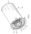
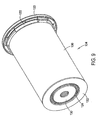
- FIGS. 4-9 are perspective views illustrating components and the construction of the filter element of the filter apparatus of FIGS. 1-3 .
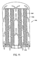
- FIGS. 10-11 are schematic illustrations of two potential flow patterns through a filter apparatus according to the invention, with FIG. 10 illustrating the flow pattern in the exemplary embodiment of FIG. 1 , and FIG. 11 showing an alternate flow pattern for use in alternate embodiments of the invention.
- FIGS. 12 and 13 are an exploded perspective view, and an orthographic cross-section, respectively, of a filter housing of the exemplary embodiment of the filter apparatus shown in FIGS. 1-9 .
- FIGS. 14-16 are roll-out views illustrating a series of steps involved in engaging complimentary keying and locking features in a filter element and housing of the exemplary embodiment of the filter apparatus shown in FIG. 1 .
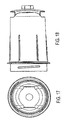
- FIGS. 17-22 are external perspective and orthographic views of the housing of the exemplary embodiment of FIGS. 1-3 , showing the outside appearance of the housing.
- FIG. 23 is a perspective view of a filter base of the exemplary embodiment of FIGS. 1-3 .
- FIGS. 24-26 are roll-out views illustrating a series of steps involved in engaging complimentary keying and locking features in a filter base and housing of the exemplary embodiment of the filter apparatus shown in FIGS. 1-3 .
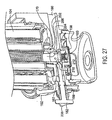
- FIGS. 27-28 are perspective partial sections of the exemplary embodiment of the filter apparatus of FIGS. 1-3 , with FIG. 27 showing a drain/vent valve of the filter apparatus in a closed position, and with FIG. 28 showing the drain/vent valve of the filter apparatus in an open position.
- FIG. 29 is a cross-sectional view of another embodiment of the filter apparatus wherein the media packs are not concentric.
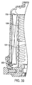
- FIG. 30 is a cross-sectional view of another embodiment of the filter apparatus where the flow tube is permanently attached to the housing.
- FIG. 31 is a cross-sectional view of another embodiment with the flow tube as part of the filter element.
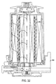
- FIG. 32 is a cross-sectional view of another embodiment with the flow tube as part of the base.
- FIG. 33 is a cross-sectional view of another embodiment with a one-piece end cap at the upper end and an end cap at the lower end which has an integral flow path to the outside of the filter.
- FIG. 34 is a cross-sectional view of another embodiment with an outer media pack and the flow tube is connected to the end cap.
- FIG. 35 is a cross-sectional view of another embodiment where the flow tube is connected to the housing.
- FIG. 36 is a cross-sectional view of another embodiment with an outer media pack and the flow tube is connected to the base.
- FIG. 37 is a cross-sectional view of another embodiment with a flow tube wherein one portion of the flow tube is attached to the housing and the other portion of the flow tube is attached to the filter element.
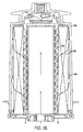
- FIG. 3 8 is a cross-sectional view of another embodiment with a flow tube wherein one portion of the flow tube is attached to the housing and the other portion of the flow tube is attached to the base.
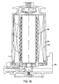
- FIG. 39 is a cross-sectional view of another embodiment with a flow tube wherein a portion of the flow tube is attached to the top end cap of the filter element and the other portion is attached to the base.
- FIG. 40 is a cross-sectional view of another embodiment with the housing, flow tube and filter permanently attached.
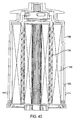
- FIG. 41 is a cross-sectional view of another embodiment wherein the inner and outer media packs are separate and the two bottom end caps are attached together.
- FIG. 42 is a cross-sectional view of another embodiment which uses a pin to engage the valve.
- FIG. 43 is a cross-sectional view of another embodiment with a pin which engages the end cap.
- FIG. 44 is a cross-sectional view of another embodiment with a knob engaging the center tube.
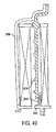
- FIG. 45 is a perspective view of another embodiment with a locking collar.
- FIG. 46 is a perspective view of another embodiment which utilizes a rotating bolt to attach the base to the housing.
- FIG. 47 is a perspective view of another embodiment of the filter element with overmolded seals.
- FIG. 48 is a perspective view of another embodiment of a filter with an RFID tag and an RFID reader.
- FIG. 49 is a cross-sectional view of another embodiment which shows a spring at the base end of the filter element.
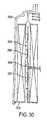
- FIG. 50 is a cross-sectional view of another embodiment which shows a flow tube with a first and second portions and a spring located between the two portions.
- FIG. 51 is a cross-sectional view of another embodiment of the filter element with the wrapping attached to the media with an adhesive.
- FIG. 52 is an enlarged view of the circled area in FIG. 51 .
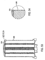
- FIG. 53 is a cross-sectional view of another embodiment of the filter element with the wrapping potted into the end caps.
- FIG. 54 is an enlarged cross-sectional view of the area shown in the circle in FIG. 53 .
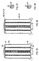
- FIG. 55 is a cross-sectional view of another embodiment of the filter element with the wrapping spaced from the end cap.
- FIG. 56 is a cross-sectional view of another embodiment of the filter element.
- FIG. 57 is an enlarged cross-sectional view of the area shown in the circle in FIG. 56 .
- FIG. 58 is an enlarged cross-sectional view of another embodiment of the area shown in FIG. 56 .
- FIG. 59 is a cross-sectional view of another embodiment of the filter apparatus with water separation.
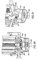
- FIG. 60 shows another embodiment of the filter apparatus with water separation.
- FIG. 61 is another view of the embodiment shown in FIG. 60 .
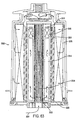
- FIG. 62 is a cross-sectional view of another embodiment with water separation.
- FIG. 63 is a cross-sectional view of another embodiment with different filter media packs.
- FIGS. 1-3 show an exemplary embodiment of a filter apparatus 100, according to the invention, including a filter base 102, a filter element 104, and a filter housing 106. As shown generally in FIG. 1 , and described in more detail below, the element 104 and housing 106 are configured to be joined together, to form a filter cartridge 108, which is then sealingly joined to the base 102.
- a filter apparatus may also include additional components, such as the fluid pre-heater 112, or the water separator 110 shown in FIG. 1 .
- the filter element 104 includes inner and outer substantially tubular-shaped media packs 114, 116 disposed about a longitudinal axis 118 of the filter element that will be aligned with a longitudinal axis 120 of the exemplary embodiment to the filter apparatus 120, as indicated in FIG. 1 .
- the filter element 104 also includes a first end cap 122, an outer seal 123, an inner seal 125, second end caps 130, 132, and an outer wrapper 136, which will be explained in more detail below.
- the media packs may be formed from pleated filter material, but in other embodiments of the invention, other forms of media may also be utilized in practicing the invention. It will also be noted that, although the inner and outer media packs 114, 116 in the exemplary filter apparatus 100 are substantially annular shaped, and concentrically positioned about the common axis, but in other embodiments of the invention, this need not be the case. In other embodiments of the invention, the media packs may have a tubular shape that are not annular in cross-section, and not necessarily sharing the same axis, such as, the embodiment shown in FIG. 29 .
- each of the inner and outer media packs 114, 116 is potted into the first end cap 122 in a manner defining a fluid flow space 124 between the inner and outer media packs 124, 116 for receiving a flow of fluid directed in a parallel, bi-directional flow pattern through the inner and outer media packs 114, 116, as illustrated in FIG. 4 .
- fluid enters the open space in the center of the inner media pack 114 of the filter element 104 through an opening 126 in the center of the first end cap 120, and exits the filter element 104 through the a series of slots 128 in the first end cap 120 that are aligned with the space 124 between the inner and outer media packs 114, 116.
- the opposite ends of the inner and outer media packs 114, 116 are blocked by the second end caps 130, 132, which, as shown in FIG. 3 , include annular sealing ridges on their outer and inner peripheries, respectively for sealing against an annular-shaped sealing portion of a flow tube 134 of the housing 106.
- the annular-shaped sealing portion of the flow tube 134 blocks fluid from axially entering the second end (upper end as shown in FIG. 1 ) of the space 124 between the inner and outer filter medias 114, 116.
- such a parallel, bi-directional flow pattern can also be provided by configuring the element and base such that fluid enters the element around its outer periphery and exits through the space between the inner and outer elements, as shown in FIG. 10 .
- a filter element incorporating a parallel, bi-directional flow pattern, in accordance with the invention has been shown to provide a substantial increase in filter capacity, within a given volume, as compared to prior fluid filters using conventional flow patterns. Although such a parallel, bi-directional flow pattern will generally be preferred in practicing the invention, it will be understood that the invention may also be practiced with other types of fluid flow patterns through the element.
- the filter element 104 of the exemplary embodiment also includes a fluid-permeable outer wrapping 136 attached over the outer periphery of the outer media pack 116, to maintain spacing between the pleats of the outer media pack 116.
- a fluid-permeable outer wrapping 136 attached over the outer periphery of the outer media pack 116, to maintain spacing between the pleats of the outer media pack 116.
- other methods of maintaining spacing may be utilized, such as beads of adhesive around the periphery, or sputtered on beads of adhesive on the outer periphery.
- a wrapper it may be attached in a number of configurations, some of which are detailed in Attachment 3.
- the housing 106 of the exemplary embodiment of the filter apparatus 100 shown in FIGS. 1-3 includes a dome 138, a flow tube retainer/clip 140, a spring 142, and a ramp seal 144, and the flow tube 134.
- the flow tube 134 is configured to fit into the space 124 between the inner and outer media packs 114, 116.
- the flow tube 134 is attached to the closed end of the dome 138 of the housing 106 with a retainer/clip arrangement, formed by an annular rim 146 on the flow tube retainer 140 in conjunction with several snap action tabs 148 extending from the end of the flow tube 134 that lock over the annular rim 146 of the flow tube retainer 140.
- the flow tube retainer 140 is a separate structure from the dome 138, which is attached in an opening 150 in the closed end of the dome 138 of the filter housing 104, by an adhesive, welding, brazing, a press fit, or a thread, or other attachment methods appropriate to the materials utilized for forming the dome 138 and retainer 140. In other embodiments of the invention, however, the retainer 140 and/or the rim 146 may be formed integrally with the remainder of the dome 138.
- the retainer 140 of the exemplary embodiment also includes a threaded port 152 therein, for attachment of a threaded plug, or accessories such as a heater, a water separator device, etc.
- the retainer 140 also includes a plurality of flow slots 154 for facilitating fluid flow into, or out of, the inner media pack 114 at the closed end of the dome 138.
- the spring 142 is a helical-wound compression spring, in the exemplary embodiment. Mating ends of the flow tube 134 and the retainer 140 are configured to provide spring seats for capturing the spring 142, in such a manner that the spring 142 urges the flow tube 134 to move in a direction away from the retainer 140.
- the snap action tabs 148 of the flow tube 134 are of such a length that the spring 142 holds the remainder of the flow tube 134 at a fixed distance away from the retainer 140, but allowing the spring 142 to be compressed, so that the flow tube 134 can move a short distance toward the retainer 140, when sufficient force is applied to the opposite end of the flow tube 134 to overcome the force of generated by the spring 142.
- the base 102 may include a block 156, a flow control valve 158, a torsion spring 160, and a drain valve 162.
- the block 156 defines a mounting flange 164 for mounting the filter apparatus 100 on a structure, such as the engine block of an engine.
- the block 156 also defines an inlet port 166, an outlet passage 167 connected to an outlet port 168, a drain/vent port 169, and receptacles 170, 172 for the rotating flow control valve 158 and the drain valve 162 respectively.
- the block 156 of the base 102 further defines an integral collar 174 for receiving and retaining the housing 104, and first and second sealing surfaces 176, 178, all of which are described in more detail below.
- the first end cap 122 of the element 104 includes a series of long and short keys 180, 182, extending partially around the outer periphery of the first end cap 122, and having axially extending locking tabs 180a, 180b, 182a, 182b attached to opposite ends of the long and short keys 180, 182. As shown in FIGS. 5-7 , the first end cap 122 of the element 104 includes a series of long and short keys 180, 182, extending partially around the outer periphery of the first end cap 122, and having axially extending locking tabs 180a, 180b, 182a, 182b attached to opposite ends of the long and short keys 180, 182. As shown in FIGS.
- the inner surface of the dome 138, adjacent the open end of the dome 138, is configured to provide complimentary keys 184a-184e that are spaced and configured to define a complimentary mating structure for receiving the long and short keys 180, 182 of the first end cap 122 of the filter element 104, and the locking tabs 180a, 180b, 182a, 182b of the long and short keys 180, 182 of the first end cap 122.
- the inside surface of the first end cap 122 of the filter element also includes a plurality of castellated mounting buttons 188, each having a slot 190 in the distal end thereof for receiving the distal end 192 of the flow tube 134, when the element 104 is inserted into the dome 138.
- FIGS. 14-16 are roll-out views of the mating keys 180, 182, 184a-d of the first end cap 122 of the filter element 104 and the open end of the dome 138 of the housing 106.
- the inner surface of the open end of the dome 138 includes a series of keys 184a-184e, of various sizes and spacings specifically configured to provide a sequence of long and intermediate openings 186a, 186b, with which the long and short keys 180, 182 respectively of the first end cap 122 of the filter element 104 must be aligned, in order for the element 104 to be inserted into the housing 106.
- the keys 184a-184e are further configured and spaced to provide a series of short slots 186c for receiving the locking tabs180a-b, 182a-b, on the long and short keys of the first end cap 122.
- the distal end 192 of the flow tube 134 is inserted into the space 124 between the inner and outer media packs 114, 116 of the _ filter element 104.
- the filter is rotated to align the long and short keys 180, 182 of the first end cap 122 of the filter element 104 with the long and intermediate spaces 186a, 186b of the dome 138, as shown in FIG. 12 , in order to allow the element 104 to be inserted into the dome 138.
- the distal end 192 of the flow tube 134 engages the slots 190 in the mounting buttons 188 of the first end cap 122, and the spring 142 in the housing 108 is compressed, allowing the element 104 to enter the dome 138, as shown in FIG. 15 , with the keys 180, 182 in the end cap 122 aligned with long and intermediated length slots 166a, 186b of the dome 138. As shown in FIG. 15 , with the keys 180, 182 in the end cap 122 aligned with long and intermediated length slots 166a, 186b of the dome 138. As shown in FIG.
- the element 104 is then rotated to properly align the locking tabs 180a-b, 182a-b of the long and short keys with corresponding slots 186a, 186c in the dome, and axial pressure on the element 104 is released, to allow the spring 144 to push the long and short keys 180, 182 and locking tabs 180a-b, 182a-b of the first end cap 122 into seating engagement with the keys 184a-e and slots 186a-c of the dome 138, to thereby fixedly attach the element 104 to the housing 106.
- the element 104 may be secured to the housing 106 by an adhesive or other attachment methods appropriate for the materials selected for the element 104 and the housing 106.
- the complexity of the keying arrangements described above may be dispensed, in favor of other methods of attaching the element 104 to the housing 106, or leaving the housing 106 separate from the element 104.
- the element 104 and housing 106 joined with an arrangement, such as the locking keyed structure described above in relation to the exemplary embodiment of the filter apparatus 100, so that the element 104 may be replaced and the housing 106 reused, by first removing the spent element, by performing the steps described in relation to FIGS. 14-16 in reverse order, and then installing a replacement element 104 in the manner described above in relation to FIGS. 14-16 .
- the cartridge 108 is installed into the integral collar 174 of the base 102.
- the inner surface of the integral collar 174 of the base 102 includes a series of ramp-like structures 194, which are engaged by complimentary ramps 196 formed on the outside of the dome 138, adjacent the open end of the dome 138. As shown in FIGS. 12 , and 23 , the inner surface of the integral collar 174 of the base 102 includes a series of ramp-like structures 194, which are engaged by complimentary ramps 196 formed on the outside of the dome 138, adjacent the open end of the dome 138. As shown in FIGS.
- the ramp-like structures 194 and ramps 196 are configured to include keying and stops so that the housing 108 can only be fitted axially.into the integrated collar 174 when the keying features on the ramps 196 of the housing 108, and the ramp-like structures 194 of the base 102 are correctly aligned with one another. After the housing 108 has been properly aligned and inserted axially into the base 102, the housing 108 is rotated with respect to the base 102 to bring the stops on the ramps 196 and ramp-like structures 194 into contact with one another, to thereby ensure a predetermined relative alignment of the housing 108 to the base 102.
- the filter element 104 of the exemplary embodiment includes an outer seal 123 and an inner seal 125 attached to the first end cap 122.
- the outer seal 123 wraps around the outer end of the dome 138 of the housing 108, when the element 104 is properly installed in the housing 108.
- the outer and inner seals 123, 125 respectively, form seals between the element 104 and the first and second sealing surfaces 176; 178 of the base 102, when the cartridge 108 is properly locked into the base 102.
- the ramps 196 and ramp like structures 194, in conjunction with the axially extending keyed structures 204, 206 form a first set of complimentary keyed, structures for attaching the filter element 104 to the base 102 in a particular rotational alignment of the filter element 104 with the base 102.
- the complimentary keying of the element 104, and housing 106 form a second set of complimentary keyed, structures for attaching the filter element 104 to the housing 106 in a particular rotational alignment of the filter element 104 with the housing 102.
- the housing 106 includes an integral ramp seal 144, for covering and closing the juncture of the base 102 and the housing 106, when the cartridge 108 is locked into the base 102, to preclude dirt, water or other foreign matter from entering the space occupied by the ramps 196 and ramp-like structures 194.
- the housing 106 of the exemplary embodiment also includes handles 198 and ribs 200 positioned to facilitate tool-less removal of the cartridge 108 from the base 102. As shown in FIGS. 18-22 , the handles 198 and ribs 200, and other features of the housing 106 of the exemplary embodiment have been selected to provided a pleasing aesthetic appearance. Those skilled in the art will recognize that in other embodiments of the invention, such features may or may not be included, and may have appearances different from the ones depicted herein.
- the exemplary embodiment of the filter apparatus 100 may also include an automatic valve for blocking or restricting fluid from flowing into the element 104, or from the inlet port 166 when the cartridge 108 is not properly secured in the base 102.
- the valve may include the valve 158, and torsion spring 160, secured in the receptacle 170 of the base 102, by a snap ring 202, as shown in FIGS. 3 , 23 , 27 , and 28 . As shown in FIGS.
- the first end cap 122 of the filter element 104, and the valve 158 include complementary axially extending keyed structures 204, 206 which are sized and oriented so that they must properly mate with one another for the filter element 104 to be inserted in to the filter base 102 in the manner indicated by the step shown in FIG. 24 .
- the complimentary axially extending keyed structures 204 of the filter element 104 rotate the valve from the closed position, shown in FIG. 27 , to the open position shown in FIG. 28 , so that fluid can flow from the inlet passage 166 into the filter element 104.
- the drain/vent valve 162 on the exemplary embodiment of the filter apparatus 100 may serve two functions.
- the drain/vent valve 162 is a two position, manually operable, shuttling spool valve, having an exposed handle 206 at one end for moving the drain/vent valve from a first position, as shown in FIG. 27 , to a second position as shown in FIG. 28 .
- the second end of the drain/vent valve includes a conical shaped locking pin 210, for engaging a complimentary recess 212 in the valve 158.
- the drain/vent valve 162 blocks air or fluid from flowing between the outlet passage 167 and the drain/vent port 169, and the conical shaped locking pin 210 is positioned within the complimentary locking recess 212 in the valve 158.
- the locking pin 210 of the drain/vent valve 162 is engaging the complimentary locking recess in the valve 158, not only is the valve 158 locked in the open position, but also, the entire cartridge 108 is locked against rotation, by the locking pin 210 and recess 212, to preclude loosening of the cartridge, under the forces of vibration, for example.
- the drain/vent valve 162 allows air or fluid to flow between the outlet passage 167 and the drain/vent port 169, so that the element 104 can be drained, and the conical shaped locking pin 210 is disengaged from the complimentary locking recess 212 in the valve 158.
- the locking pin 210 of the drain/vent valve 162 is disengaged from the complimentary locking recess 212 in the valve 158, the filter cartridge 108 and valve 158 are free to rotate, so the filter cartridge 108 can be disengaged from the base 102.
- the axially extending keyed projections 204, 206 of the first end cap 122 will rotate the valve 158 toward its closed position, until the axially extending keyed projections 204, 206 disengage due to axial movement of the cartridge 108 with respect to the base 102, caused by the ramps 196 and ramp-like structures 194.
- the torsion spring 160 will urge the valve to rotate further to the closed position of the valve 158, as shown in FIG.28 .
- the drain/vent valve 162 functions as a drain.
- the drain/vent valve functions as an air vent, to allow fluid to drain from the element 104 through the opening 152 in the closed end of the dome 138 of the housing 108.
- the filter packs may not be concentric and the filter packs may not be annular.
- the outer media pack 316 may have an axis 317.
- the inner media pack 314 may have an axis 315. In this embodiment, the axis 315 is not aligned with axis 317.
- the inner media pack 314 is oval in cross-section.
- the inner media pack and the outer media pack may have other shapes in cross-section, such as polygons, i.e. triangular, rectangular, square, pentagon, hexagon or other shapes. These configurations may be used with any of the embodiments disclosed herein, as appropriate.
- the center tube may be permanently attached to the housing.
- the flow tube 434 may be permanently attached to the filter housing 406.
- the flow tube may be attached by a snap fit, welding, threaded connection or press fit.
- the configuration may be used with any of the embodiments disclosed herein, as appropriate.
- the flow tube may be part of the filter element.
- the flow tube 534 is part of the filter element 504.
- the flow tube 534 may be connected to the end cap 530.
- the flow tube may be connected to the other end cap 522. This configuration may be used with any of the embodiments disclosed herein, as appropriate.
- the flow tube may be part of the base.
- the flow tube 634 is part of the base 602.
- the flow tube may be connected by a snap fit, welding, threaded connection or press fit. This configuration may be used with any of the embodiments disclosed herein, as appropriate.
- FIG. 33 shows another embodiment.
- the filter apparatus may have a one-piece end cap 730 at the upper end and an end cap 722 at the lower end which has an integral flow path 723 to the outside of the filter.
- the end cap 722 may be one part or the end cap 722 may be two or more parts connected together. This configuration may be used with any of the embodiments disclosed herein, as appropriate.
- the filter apparatus may have a single outer element and no inner element.
- the filter element 804 may include only an outer media pack 816.
- the flow tube 834 may include a solid wall 835.
- the flow tube 834 may be connected to the filter.
- the flow tube 834 may be connected to the end cap 830.
- the flow tube 934 may be connected to the housing 906.
- the filter element 904 may include only an outer media pack 916.
- the flow tube 1034 may be connected to the base 1002.
- the filter element 1004 may include only an outer media pack 1016.
- FIG. 37 is a cross-sectional view of another embodiment with a two part flow tube.
- the first portion 1135 of the flow tube is attached to the housing 1106.
- the second portion 1137 of the flow tube is attached to the filter element 1104.
- the first portion 1135 may be connected to the second portion 1137.
- the first portion 1135 may be connected to the second portion 1137 by a tab 1139 and notch 1141 configuration.
- other connection techniques may be used. This configuration may be used with any of the embodiments disclosed herein, as appropriate.
- FIG. 38 another embodiment with a two part flow center tube is shown.
- the first portion 1235 of the flow tube is attached to the housing 1206 and the second portion 1237 of the flow tube is attached to the base 1202.
- This configuration may be used with any of the embodiments disclosed herein, as appropriate.
- FIG. 39 Another embodiment with a two part flow tube is shown in FIG. 39 .
- the first portion 1335 of the flow tube is attached to the top end cap 1330 of the filter element and the second portion 1337 is attached to the base 1302.
- This configuration may be used with any of the embodiments disclosed herein, as appropriate.
- FIG. 40 another embodiment of the filter apparatus is shown.
- the housing 1506, the flow tube 1534 and the filter element 1504 are permanently attached together as an assembly 1535.
- the user merely replaces the entire assembly 1535 with a new filter assembly 1535 which includes the housing, flow tube and filter element.
- This configuration may be used with any of the embodiments disclosed herein, as appropriate.
- the inner media pack and the outer media pack could be replaced separately.
- the inner media pack 1614 and the outer media pack 1616 may be replaced separately.
- the inner media pack may have an end cap 1623 and the outer media pack may have an end cap 1625.
- the end caps may be connected together.
- the end caps may lock together with a tab 1627 and a notch 1629 as shown in FIG. 41 .
- the two end caps may snap together or may have mating ribs.
- the user may replace either one of the media pack without replacing the other media pack.
- the user can combine different media packs in order to customize the filter apparatus.
- the user may use an inner media pack made of extremely efficient water removing material with an outer media pack made of pleated cellulose of efficiency appropriate for normal operation.
- Another user may use an inner media pack made of media with fuel conditioning chemical additives and outer media pack made of less than normal efficiency pleated cellulose appropriate for higher flow operation.
- the users may decide to utilize different media packs.
- a pin 1763 may be used to engage the valve 1758.
- the pin may be biased in the closed position by a spring 1765.
- the pin 1763 When a user wishes to drain or vent the system, the user would pull the pin 1763 in direction 1771 so that the outlet passage 1767 may be connected with the drain/vent port 1769.
- the user When the user has completed draining or venting the system, the user may release the pin 1763 and the spring 1765 will return the pin to the first position.
- the pin may be used with any of the embodiments disclosed herein as appropriate.
- FIG. 43 shows another embodiment in which the pin engages the end cap.
- the pin engages the end cap 1822 which extends into the base 1802.
- the pin 1863 engages a detent 1865 in the end cap 1822.
- the user is able to lock the filter element into position to prevent rotation.
- the user would pull the pin 1863 in direction 1871 so that the end cap may rotate.
- This configuration may be used with any of the embodiments disclosed herein, as appropriate.
- FIG. 44 another embodiment of the filter apparatus is shown.
- a spring pin 1963 engages the flow tube 1934.
- the flow tube 1934 may include a detent 1965 which the pin 1963 may engage.
- a threaded drain valve may be used in place of the spring biased pin. This configuration may be used with any of the embodiments disclosed herein, as appropriate.
- the housing 2006 may include a collar 2007.
- the collar may include a ramp 2009 on the interior of the collar.
- the base 2002 may include a ramp 2011.
- the ramp may be located on the exterior of the base.
- the ramp 2009 on the collar will engage the ramp 2011 on the base.
- the housing may include an exterior ramp 2096 which may engage an interior ramp 2094 in the base.
- the collar 2007 may be used to lock the housing to the base. This configuration may be used with any of the embodiments disclosed herein as appropriate.
- FIG. 46 shows another embodiment of a locking mechanism.
- the base 2102 may include a threaded pin 2103.
- a fastener 2105 such as a wing nut, may be connected to the threaded pin 2103.
- the housing 2106 may include a notch 2107 which may be engaged by the pin 2103. After the housing has been assembled to the base, the user may position the pin 2103 in the notch 2107 and then tighten the fastener 2105. Thus, the housing may be locked to the base.
- This configuration may be used in any of the embodiments disclosed herein as appropriate.
- the filter element may include end caps with seals.
- the filter element 2204 may include an inner end cap 2230 and an outer end cap 2232.
- the end caps may include seals 2231 and 2233, which are connected to the end caps.
- the seals may be connected to the end caps by overmolding.
- the seals may be made of a material different than the end caps.
- the seals may be made of an elastomer and the end caps may be made of a plastic. This seal configuration may be used with any of the embodiments disclosed herein as appropriate.
- the filter apparatus may also include a system for providing information relating to the filter apparatus.
- the filter apparatus 2300 may include a radio frequency identification (RFID) system.
- the filter 2304 may include an RFID tag 2305 and the base 2302 may include an RFID reader 2303.
- the reader 2303 When the filter is positioned into the base, the reader 2303 will be able to read the tag 2305.
- the tag will be able to provide information to the system, such as whether the proper filter has been utilized, the manufacturer of the filter, the date of manufacture of the filter and other filtration parameters.
- the system will indicate whether the filter change has been completed and the mileage and/or date of the filter change.
- the reader may be located in another location on the vehicle and may be able to read information concerning other filters, such as the primary fuel filter, secondary fuel filter, primary lubrication filter or secondary lubrication filter.
- Other systems for providing information concerning the filter apparatus may include two dimensional bar codes, three dimensional bar codes, resistors, reed switches, mechanical switches, magnets, conductive plastic, conductive ink, or other systems. These configurations may be included in any of the embodiments disclosed herein as appropriate.
- a spring is located at the base end of the flow tube.
- a spring 2442 is located between the flow tube 2434 and the end cap 2422.
- the center tube 2434 may be connected to the housing 2406. This configuration may be used with any of the embodiments disclosed herein, as appropriate.
- the flow tube 2534 includes a first portion 2535 and a second portion 2537.
- the first portion 2535 is connected to the housing 2506.
- the second portion 2537 is connected to the end cap 2522.
- a spring 2542 may be located between the first portion 2535 and the second portion 2537. This configuration may be used with any of the other embodiments disclosed herein as appropriate.
- the outer wrapping may be attached to the filter element in several ways. Referring to FIGS. 51 and 52 , the outer wrapping 2736 may be applied to the filter material 2737 with an adhesive 2739. If the filter material 2737 is a pleated filter, then the adhesive may be applied to the pleat tips. The outer wrapping 2736 will maintain the spacing of the pleats.
- the configuration may be used with any of the embodiments disclosed herein, as appropriate.
- the outer wrapping 2836 may be potted into the end cap 2816.
- the outer wrapping 2936 may be spaced from the end cap 2916 and/or end cap 2922 to create a gap 2917 and gap 2923.
- the outer wrapping 3036 may be attached to the outside diameter of the end cap 3016 as shown in FIG. 57 .
- the outer wrapping 3136 may be folded over the end cap 3116 as shown in FIG. 58 . Any of these configurations may be used with any of the embodiments disclosed herein, as appropriate.
- the filter apparatus may also include water separation.
- the filter is shown with the dome 3238 in an upward position.
- the filter apparatus may include a bowl 3241 connected to the base 3202.
- the bowl may include a drain knob 3243 and a water indicator 3245.
- the filter may include a coalescing material 3247 on the output side of the inner media pack 3214 and a coalescing material 3249 on the output side of the outer media pack 3216.
- the coalescing material causes the water to coalesce into larger droplets and flow to the bowl 3241 as shown by arrows 3250.
- the water 3251 accumulates at the bottom of the bowl 3241 where it may be drained using the drain knob 3243. This configuration may be used with any of the embodiments disclosed herein, as appropriate.
- FIGS. 60 and 61 another embodiment of water separation is shown.
- the filter apparatus is shown with the dome in the up position.
- the bowl 3341 may include a water stripping screen 3361.
- the fuel and water mixture would enter the bowl through the inlet port 3366.
- the fuel and water mixture would enter the bowl and then pass upwards through the screen 3361.
- the fuel and water mixture would continue upwards toward the filter as shown by arrow 3363 in FIG. 60 .
- the water would be stripped from the fuel water mixture by the water stripping screen 3361.
- the water would then travel towards the bottom of the bowl as shown by arrows 3349.
- the water 3351 would then accumulate at the bottom of the bowl and could be drained using the drain knob 3343. This configuration could be used with any of the embodiments disclosed herein, as appropriate.
- the filter apparatus may include a bowl 3441 connected to the dome 3438.
- the filter element 3404 may include a coalescing material 3471 at the interior of the inner media pack 3414.
- the outer media pack 3416 may include a coalescing material 3477 on the outer surface. As the fuel water mixture as shown by arrow 3479 engages the coalescing material 3477, the coalescing material separates the water as shown by arrow 3481 which then falls to the bowl 3441.
- coalescing screens 3483 may be placed at the openings in the retainer clip or similar structure. These coalescing screens would separate the water prior to engaging the outer media pack 3416.
- the coalescing screens 3483 may be used instead of the coalescing material 3477 or may be used in conjunction with the coalescing material 3477 on the outer media pack 3416. These configurations may be used with other embodiments disclosed herein, as appropriate.
- the filter apparatus may include various filter media. Referring to FIG. 63 , one embodiment of the filter apparatus is shown.
- the filter apparatus 3500 may include a first inner media material 3514, a second inner media material 3515 and an outer media material 3516.
- the media material 3514 may be a fluid conditioning material.
- the media 3514 may be an acid neutralizing material such as calcium carbonate.
- the second inner media material 3515 may be a filter material.
- the outer media pack 3516 may also be a filter material.
- the inlet fluid flow is represented by arrow 3521. A portion of the inlet flow will create a by-pass flow as shown by arrow 3525 and enter the filter media 3514 at holes 3523.
- the by-pass flow 3523 will continue through the second inner filter 3515 and exit at the holes 3527 to proceed along the flow tube 3534.
- the remaining flow 3531 will continue upwards and pass through the filter media pack 3516 before it enters the flow tube 3534.
- the media 3514, 3515 and 3516 may include many different media, such as pleated cellulose, spun bonded polyester, impregnated films, synthetic nanofibers, chemical treatment beds, depth type beds of recycled material, coalescing screens, and composite materials. These media may be used in a variety of combinations. This configuration may be used in any of the embodiments disclosed herein, as appropriate.
Landscapes
- Chemical & Material Sciences (AREA)
- Chemical Kinetics & Catalysis (AREA)
- Filtration Of Liquid (AREA)
- Lubrication Details And Ventilation Of Internal Combustion Engines (AREA)
- Filtering Of Dispersed Particles In Gases (AREA)
- Separation By Low-Temperature Treatments (AREA)
- Surgical Instruments (AREA)
- Centrifugal Separators (AREA)
Claims (20)
- Filtervorrichtung mit einem Filterelement (104), einem Filtersockel (102) und einem Filtergehäuse (106), wobei
die Außenseite des Filtergehäuses (106) erste Rampen (196) beinhaltet, der Filtersockel (102) komplementäre rampenartige Anordnungen (194) beinhaltet, die so gestaltet sind, dass sie die ersten Rampen (196) des Filtergehäuses (106) erfassen;
die ersten Rampen (196) und rampenartigen Anordnungen (194) Kodierungen und Arretierungen beinhalten und zusammen eine erste Gruppe komplementärer Kodieranordnungen bilden,
der Filtersockel (102) ein Ventil (158) beinhaltet, das so vorgespannt ist, dass es schließt, wenn das Filterelement (104) aus dem Filtersockel (102) entfernt wird, und dass es durch das Einsetzen des Filterelements (104) auf den Filtersockel (102) automatisch geöffnet wird, wobei das Ventil (158) zwischen einer ersten Stellung und einer zweiten Stellung drehbar ist, wobei das Ventil (158) einen Fluss von Fluid in das oder aus dem Filterelement (104) drosselt, wenn sich das Ventil (158) in der ersten Stellung befindet und wobei das Ventil (158) einen Fluss von Fluid in das oder aus dem Filterelement (104) zulässt, wenn sich das Ventil (158) in der zweiten Stellung befindet, wobei ferner das Ventil (158) gedreht wird, indem das Filterelement (104) gedreht wird und das Ventil (158) eine kodierte, axial vorspringende Anordnung umfasst, um eine komplementär kodierte, axial vorspringende Anordnung (204, 206) eines Filterelements (104) zu erfassen, wobei die komplementär kodierten, axial vorspringenden Anordnungen (204, 206) des Ventils (158) und des Filterelements (104) so arbeiten, dass das Ventil (158) aus der ersten, geschlossenen Stellung in die zweite, geöffnete Stellung bewegt wird, wenn das Filterelement (104) in den Filtersockel (102) eingesetzt wird, und sicherzustellen, dass das Filterelement (104) das passende Filterelement (104) für die Verwendung mit dem genannten Filtersockel (102) ist. - Filtervorrichtung nach Anspruch 1, bei der der Filtersockel weiterhin einen Bund (174) beinhaltet, wobei eine Innenfläche des Bundes (174) die rampenartigen Anordnungen (194) beinhaltet.
- Filtervorrichtung nach Anspruch 1 oder 2, bei der das Ventil (158) in der ersten Stellung das Fluid von der Einlassöffnung (166) beim Fließen in das Filterelement (104) drosselt, und in der zweiten Stellung das Fluid von der Einlassöffnung (166) in das Filterelement (104) einlässt.
- Filtervorrichtung nach einem beliebigen der Ansprüche 1 bis 3, bei der eine Feder (160) vorgesehen ist, um das Ventil (158) in Richtung der ersten Stellung zu drücken.
- Filtervorrichtung nach einem beliebigen der vorhergehenden Ansprüche, bei der eine Endkappe (122) des Filterelements (104) und das Ventil (158) entsprechende komplementäre Kodieranordnungen (204, 206) beinhalten.
- Filtervorrichtung nach Anspruch 5, bei der sich die komplementären Kodieranordnungen (204, 206) in axialer Richtung erstrecken und sich in axialer Richtung erfassen.
- Filtervorrichtung nach einem der vorhergehenden Ansprüche, bei der das Ventil (158) eine Verschlussaussparung (212) beinhaltet, wobei die Verschlussaussparung (212) von einem Verschlussstift (210) erfasst wird, um eine Drehung des Ventils (158) zu verhindern.
- Filtervorrichtung nach Anspruch 7, bei der die Verschlussaussparung (212) von dem Verschlussstift (210) erfasst wird, um das Ventil (158) in der zweiten Stellung zu sichern.
- Filtervorrichtung nach Anspruch 7 oder 8, mit weiterhin einer Abfluss-/Entlüftungsöffnung (169) und einem Abflussventil (162), wobei das Abflussventil (162) beweglich ist, um dem Fluid den Abfluss zu ermöglichen und zu verhindern, dass Fluid aus der Abfluss-/Entlüftungsöffnung (169) austritt.
- Filtervorrichtung nach Anspruch 9, bei der das Abflussventil (162) den Verschlussstift (210), der die Verschlussaussparung (212) erfasst, beinhaltet.
- Filtervorrichtung nach einem der Ansprüche 1 bis 10, mit weiterhin einer zweiten Gruppe von komplementären Kodieranordnungen, um das Filtergehäuse (106) an dem Filterelement (104) anzubringen.
- Filtervorrichtung nach Anspruch 11, bei der das Filterelement (104) ein Filtermedium (114, 116) und eine erste Endkappe (122) beinhaltet, wobei die erste Endkappe (122) eine Mehrzahl von ersten Kodierelementen (180, 182) der zweiten Gruppe aufweist, die auf einer Außenfläche der ersten Endkappe (122) angeordnet sind;
das Filtergehäuse (106), in das das Filterelement (104) eingesetzt wird, ein offenes Ende beinhaltet, um es zu ermöglichen, dass das Filterelement in das Filtergehäuse (106) eingesetzt und aus diesem entfernt werden kann, und das Filtergehäuse (106) eine Innenfläche mit einer Mehrzahl von zweiten Kodierelementen (184a - 184e) aufweist;
so dass, wenn das Filterelement (104) in das Filtergehäuse (106) eingesetzt wird und die ersten Kodierelemente (180, 182) die zweiten Kodierelemente (184a - 184e) erfassen und das Filterelement (104) fest mit dem Gehäuse (106) verbinden, die Drehbewegung des Filterelements (104) im Verhältnis zu dem Filtergehäuse (106) begrenzt wird, so dass das Filterelement (104) in einer bestimmten Drehausrichtung fest mit dem Gehäuse (106) verbunden ist. - Filtervorrichtung nach Anspruch 12, bei der das Filterelement (104) in axialer Richtung daran gehindert wird, sich in Richtung der Öffnung zu bewegen, wenn das Filterelement (104) in das Filtergehäuse (106) eingesetzt ist und die ersten Kodierelemente (180, 182) in axialer Richtung die zweiten Kodierelemente (184a - 184e) erfasst haben.
- Filtervorrichtung nach einem der Ansprüche 11 bis 13, bei der die ersten Kodierelemente (180, 182) sich in axialer Richtung erstreckende Verschlusszungen (180a, 180b, 182a, 182b) an gegenüberliegenden Enden der ersten Kodierelemente (180, 182) beinhalten.
- Filtervorrichtung nach einem der Ansprüche 12 bis 14, bei der die Mehrzahl von ersten Kodierelementen (180, 182) kurze und lange Kodierelemente beinhaltet.
- Filtervorrichtung nach einem der Ansprüche 12 bis 15, bei der die Mehrzahl von zweiten Kodierelementen (184a - 184e) Kodierelemente unterschiedlicher Größen beinhaltet.
- Filtervorrichtung nach einem beliebigen der Ansprüche 12 bis 16, bei der das Filtergehäuse (106) weiterhin Zwischenaussparungen (186a - 186c) beinhaltet, die zwischen der Mehrzahl von zweiten Kodierelementen (184a - 184e) angeordnet sind, um die Mehrzahl von ersten Kodierelementen (180, 182) aufzunehmen, wenn das Filterelement (104) in das Filtergehäuse (106) eingesetzt und aus diesem entfernt wird.
- Filtervorrichtung nach einem der Ansprüche 12 bis 17, bei der das Filtergehäuse weiterhin Zwischenaussparungen (186a - 186c) beinhaltet, die zwischen der Mehrzahl von zweiten Kodierelementen angeordnet sind, um die Mehrzahl von ersten Kodierelementen (180, 182) aufzunehmen, wenn das Filterelement (104) in das Filtergehäuse (106) eingesetzt oder aus diesem entfernt wird, und wobei die ersten Kodierelemente (180, 182) sich in axialer Richtung erstreckende Verschlusszungen (180a, 180b, 182a, 182b) an gegenüberliegenden Enden der ersten Kodierelemente (180, 182) beinhalten, wobei die Verschlusszungen (180a, 180b, 182a, 182b) in axialer Richtung in den Zwischenaussparungen (186a-186c) aufgenommen werden, wenn das Filterelement (104) in das Filtergehäuse (106) eingesetzt wird.
- Filtervorrichtung nach einem der Ansprüche 12 bis 18, bei der das Filterelement (104) in das Filtergehäuse (106) eingesetzt werden kann, indem das Filterelement (104) durch das offene Ende eingeführt wird, das Filterelement (104) gedreht wird, und das Filterelement (104) losgelassen wird, so dass die ersten Kodierelemente (180, 182) die zweiten Kodierelemente (184a - 184e) erfassen, um das Element (104) fest mit dem Gehäuse (106) zu verbinden.
- Filtervorrichtung nach einem der Ansprüche 12 bis 19, bei der das Filterelement (104) aus dem Filtergehäuse (106) entfernt werden kann, indem das Filterelement (104) in Richtung von der Öffnung weg bewegt wird, das Filterelement (104) gedreht wird, und das Filterelement (104) durch das offene Ende aus dem Filtergehäuse (106) heraus bewegt wird.
Applications Claiming Priority (2)
| Application Number | Priority Date | Filing Date | Title |
|---|---|---|---|
| US65517805P | 2005-02-22 | 2005-02-22 | |
| PCT/US2006/006018 WO2006091557A2 (en) | 2005-02-22 | 2006-02-21 | Filter apparatus |
Publications (2)
| Publication Number | Publication Date |
|---|---|
| EP1850941A2 EP1850941A2 (de) | 2007-11-07 |
| EP1850941B1 true EP1850941B1 (de) | 2011-04-13 |
Family
ID=36353357
Family Applications (1)
| Application Number | Title | Priority Date | Filing Date |
|---|---|---|---|
| EP06735607A Expired - Lifetime EP1850941B1 (de) | 2005-02-22 | 2006-02-21 | Filtervorrichtung |
Country Status (11)
| Country | Link |
|---|---|
| US (1) | US9492768B2 (de) |
| EP (1) | EP1850941B1 (de) |
| JP (1) | JP2008531249A (de) |
| CN (1) | CN101119784A (de) |
| AT (1) | ATE505246T1 (de) |
| AU (1) | AU2006216788B2 (de) |
| BR (1) | BRPI0606908A2 (de) |
| CA (1) | CA2597294C (de) |
| DE (1) | DE602006021276D1 (de) |
| MX (1) | MX2007010234A (de) |
| WO (1) | WO2006091557A2 (de) |
Cited By (2)
| Publication number | Priority date | Publication date | Assignee | Title |
|---|---|---|---|---|
| US11541336B2 (en) | 2017-02-03 | 2023-01-03 | Mann+Hummel Gmbh | Filter element, filter system comprising a filter element, and method for producing a filter element |
| EP3386708B1 (de) * | 2015-12-08 | 2023-06-07 | AC-SP Etude & Recherche En Hygiène Industrielle | Verfahren zur integration eines filtertragenden radioidentifikationschips, filterungsvorrichtung und verfahren zur herstellung eines filterträgers |
Families Citing this family (120)
| Publication number | Priority date | Publication date | Assignee | Title |
|---|---|---|---|---|
| WO2006012031A1 (en) | 2004-06-29 | 2006-02-02 | Donaldson Company, Inc. | Liquid filter arrangement and methods |
| US8057669B2 (en) | 2005-02-22 | 2011-11-15 | Baldwin Filters, Inc. | Filter element and filter assembly including locking mechanism |
| BRPI0610531A2 (pt) | 2005-04-05 | 2010-06-29 | Donaldson Co Inc | elemento filtrante com arranjo, método de filtração e método de construção |
| JP4847526B2 (ja) * | 2005-07-20 | 2011-12-28 | スリーエム イノベイティブ プロパティズ カンパニー | 流体濾過システム |
| US7959714B2 (en) | 2007-11-15 | 2011-06-14 | Cummins Filtration Ip, Inc. | Authorized filter servicing and replacement |
| US8114183B2 (en) * | 2005-09-20 | 2012-02-14 | Cummins Filtration Ip Inc. | Space optimized coalescer |
| ES2545952T3 (es) * | 2006-08-10 | 2015-09-17 | Aquis Wasser-Luft-Systeme Gmbh, Lindau | Depósito |
| DE102006044744C5 (de) | 2006-09-20 | 2021-04-01 | Aquis Wasser-Luftsysteme GmbH Lindau, Zweigniederlassung Rebstein | Wasserfiltervorrichtung mit Verschlüsselungsstruktur |
| DE202007008473U1 (de) | 2007-06-13 | 2008-10-23 | Mann+Hummel Gmbh | Filtereinrichtung, insbesondere Flüssigkeitsfilter |
| WO2008157244A1 (en) * | 2007-06-14 | 2008-12-24 | Donaldson Company, Inc. | Liquid filter arrangement and methods |
| EP2173665B2 (de) * | 2007-07-31 | 2017-10-18 | Laica S.p.A. | Perkolationsfiltersystem |
| WO2009018454A2 (en) | 2007-08-02 | 2009-02-05 | Donaldson Company, Inc. | Crankcase ventilation filter assembly; components; and, methods |
| GB0715269D0 (en) * | 2007-08-04 | 2007-09-12 | Parker Hannifin Ltd | Filter assembly |
| GB0715247D0 (en) * | 2007-08-04 | 2007-09-12 | Parker Hannifin Ltd | Filter assembly |
| US8147691B2 (en) * | 2007-09-21 | 2012-04-03 | Baldwin Filters, Inc. | Filter cartridge housing attachment systems |
| DE102007046533B3 (de) * | 2007-09-28 | 2008-07-03 | Dräger Medical AG & Co. KG | Wasserfalle mit einer Entleereinrichtung |
| JPWO2009069402A1 (ja) * | 2007-11-29 | 2011-04-07 | インテグリス・インコーポレーテッド | フィルタユニット及びフィルタカートリッジ |
| DE102007062101A1 (de) * | 2007-12-21 | 2009-06-25 | Mahle International Gmbh | Filteranlage |
| US8241493B2 (en) | 2008-06-16 | 2012-08-14 | Baldwin Filters, Inc. | Filter with ejection mechanism |
| US8128819B2 (en) | 2008-06-16 | 2012-03-06 | Baldwin Filters Inc. | Fluid filter, fluid filter assembly, and mounting method |
| US8815090B2 (en) * | 2008-06-16 | 2014-08-26 | Baldwin Filters, Inc. | Filter with water separation device |
| ITRE20080054A1 (it) * | 2008-06-23 | 2009-12-24 | Ufi Innovation Ct Srl | '' filtro per carburante '' |
| DE102008002727B4 (de) * | 2008-06-27 | 2020-12-17 | Brita Gmbh | Vorrichtung zur Behandlung von Wasser, insbesondere Filtervorrichtung, und Kartusche |
| GB0812457D0 (en) * | 2008-07-08 | 2008-08-13 | Parker Hannifin U K Ltd | A Filter |
| JP5677958B2 (ja) * | 2008-09-16 | 2015-02-25 | スリーエム イノベイティブ プロパティズ カンパニー | 直線状作動を使用したフィルタカートリッジ及びシステム |
| DE102008044292A1 (de) * | 2008-12-02 | 2010-06-10 | Brita Gmbh | Verfahren zum Entkeimen von Flüssigkeiten und Flüssigkeitsentkeimungsvorrichtung |
| US20100294707A1 (en) * | 2009-05-21 | 2010-11-25 | Cummins Filtration Ip Inc. | Multi-stage filter cartridge with snap fit filters |
| US8727134B2 (en) * | 2009-08-11 | 2014-05-20 | Mann + Hummel Gmbh | Sealing device of a filter system for filtering fluids |
| GB2477942B (en) | 2010-02-18 | 2012-07-04 | Icon Technology Systems Ltd | Water filters |
| WO2011115973A2 (en) | 2010-03-17 | 2011-09-22 | Baldwin Filters, Inc. | Fluid filter |
| WO2011115979A2 (en) | 2010-03-17 | 2011-09-22 | Baldwin Filters, Inc. | Fluid filter |
| US9682335B2 (en) | 2011-02-24 | 2017-06-20 | Saint-Gobain Performance Plastics Corporation | Modular filter capsule apparatus |
| DE102011078364A1 (de) * | 2011-06-29 | 2013-01-03 | Mahle International Gmbh | Filterelement, insbesondere für Kraftstofffilter, sowie zugehöriger Stützkörper |
| US9086186B2 (en) | 2011-10-14 | 2015-07-21 | Lincoln Industrial Corporation | System having removable lubricant reservoir and lubricant refilling station |
| DE102011119986B4 (de) * | 2011-12-02 | 2016-05-12 | Mann + Hummel Gmbh | Flüssigkeitsfilter und Filterelement mit einem Additivbehälter |
| DE102011120646B4 (de) * | 2011-12-09 | 2018-11-08 | Mann+Hummel Gmbh | Flüssigkeitsfilter und Filterelement mit Ablaufschwert eines Flüssigkeitsfilters |
| FR2984757B1 (fr) * | 2011-12-23 | 2014-06-20 | Parker Hannifin Mfg Switzerland Sa | Dispositif de vidange |
| US8709247B2 (en) * | 2012-01-27 | 2014-04-29 | Baldwin Filters, Inc. | Filter apparatus with ejection arrangement |
| EP2623175B1 (de) * | 2012-02-01 | 2016-04-27 | Delphi International Operations Luxembourg S.à r.l. | Wartbare Filtrationsanordnung |
| US20130240418A1 (en) * | 2012-03-19 | 2013-09-19 | Cummins Filtration Ip, Inc. | Filter Interface Security System |
| US8991619B2 (en) | 2012-03-26 | 2015-03-31 | Baldwin Filters, Inc. | Filter assembly with water evacuation and methods |
| DE102012209703B3 (de) * | 2012-06-11 | 2013-11-14 | Ford Global Technologies, Llc | Behälter für einen Hydraulikkreislauf |
| US9829413B2 (en) * | 2012-06-25 | 2017-11-28 | Avl Test Systems, Inc. | Emissions measurement equipment and method |
| US20140042073A1 (en) * | 2012-08-10 | 2014-02-13 | Whirlpool Corporation | Liquid filter housing with handles |
| WO2014040658A1 (en) * | 2012-09-12 | 2014-03-20 | Camfil Ab | Backing net structure |
| DE102012018662A1 (de) * | 2012-09-21 | 2014-04-17 | Mann+Hummel Gmbh | Hohlzylindrisches Filterelement für einen Flüssigkeitsfilter |
| JP5607132B2 (ja) * | 2012-11-19 | 2014-10-15 | 株式会社小松製作所 | Icタグ付きフィルターおよびフィルター用のicタグ |
| DE102012224388A1 (de) * | 2012-12-27 | 2014-07-03 | Robert Bosch Gmbh | Zweiteiliger Partikelfilter und Verfahren zu seiner Herstellung |
| JP6339101B2 (ja) | 2013-01-04 | 2018-06-06 | ボールドウィン・フィルターズ・インコーポレーテッドBaldwin Filters Inc | 3つの部分の端部キャップ及び同様な要素を含むフィルタエレメント |
| US10052575B2 (en) * | 2013-04-10 | 2018-08-21 | Clarcor Engine Mobile Solutions, Llc | Filter element |
| BR102013011661A8 (pt) * | 2013-05-10 | 2021-04-13 | Mahle Int Gmbh | filtros e base de um elemento filtrante |
| BR102013011664A2 (pt) * | 2013-05-10 | 2015-06-30 | Mahle Metal Leve Sa | Tampa e conjunto de tampa e carcaça |
| WO2014203378A1 (ja) * | 2013-06-20 | 2014-12-24 | 株式会社小松製作所 | フィルターおよびフィルターを備えた作業車両 |
| WO2014203377A1 (ja) * | 2013-06-20 | 2014-12-24 | 株式会社小松製作所 | フィルターおよびフィルターを備えた作業車両 |
| DE102013216840B4 (de) * | 2013-08-23 | 2017-05-24 | Robert Bosch Gmbh | Filtereinrichtung mit einem Ventil und einer Stelleinrichtung sowie die Verwendung der Filtereinrichtung an einer Kraftstoffversorgungseinrichtung eines Kraftfahrzeuges |
| US9274020B2 (en) | 2013-10-14 | 2016-03-01 | General Electric Company | System and a method for detecting liquid water |
| US9366388B2 (en) | 2013-10-14 | 2016-06-14 | General Electric Company | Refrigerator appliance and a method for monitoring a water filter assembly within the same |
| US9533894B2 (en) | 2013-10-14 | 2017-01-03 | Haier Us Appliance Solutions, Inc. | Water filtering system with temperature sensing |
| WO2015057956A1 (en) | 2013-10-16 | 2015-04-23 | Cummins Filtration Ip, Inc. | Electronic filter detection feature for liquid filtration systems |
| DE202013011849U1 (de) * | 2013-12-12 | 2015-03-18 | Mann + Hummel Gmbh | Filterelement |
| US10253737B2 (en) | 2013-12-12 | 2019-04-09 | Mann+Hummel Gmbh | Filter element with multi-stage water-separating action and with bayonet connection, and fuel filter having a filter element of said type |
| US10173904B2 (en) | 2014-04-10 | 2019-01-08 | Haier Us Appliance Solutions, Inc. | System for detecting a liquid and a water filter assembly |
| US10173155B2 (en) | 2014-04-10 | 2019-01-08 | Haier Us Appliance Solutions, Inc. | Water filter assembly and a system for detecting liquid |
| US10173905B2 (en) | 2014-04-10 | 2019-01-08 | Haier Us Appliance Solutions, Inc. | System for detecting a liquid and a water filter assembly |
| US20150290674A1 (en) | 2014-04-10 | 2015-10-15 | General Electric Company | Method for treating foam |
| CN106573585B (zh) | 2014-05-21 | 2020-08-28 | 卡斯特罗尔有限公司 | 流体系统及方法 |
| US9839866B2 (en) * | 2014-05-30 | 2017-12-12 | Pall Corporation | Filter elements and methods for filtering fluids |
| WO2015187665A2 (en) | 2014-06-03 | 2015-12-10 | Donaldson Company, Inc. | Filter arrangement with support core and methods |
| SG11201608399QA (en) * | 2014-06-26 | 2016-11-29 | Emd Millipore Corp | Filter structure with enhanced dirt holding capacity |
| US10413851B2 (en) | 2014-07-03 | 2019-09-17 | Donaldson Company, Inc. | Fuel filter with water separator |
| US10502477B2 (en) | 2014-07-28 | 2019-12-10 | Haier Us Appliance Solutions, Inc. | Refrigerator appliance |
| DE102015014601A1 (de) * | 2014-11-20 | 2016-05-25 | Mann + Hummel Gmbh | Filterelement mit überragendem Bajonettvorsprung |
| US9789426B2 (en) * | 2015-01-26 | 2017-10-17 | Caterpillar Inc. | Flow cap and filter assembly including flow cap |
| WO2016172289A1 (en) * | 2015-04-21 | 2016-10-27 | Ti Group Automotive Systems, Llc | Fuel filter housing |
| CN104929829A (zh) * | 2015-05-04 | 2015-09-23 | 杭龙 | 一种滤清器外壳结构 |
| US10150075B2 (en) | 2015-05-14 | 2018-12-11 | Parker-Hannifin Corporation | Pin filter |
| EP3760295A1 (de) | 2015-06-26 | 2021-01-06 | Donaldson Company, Inc. | Verbundmedien für kraftstoffströme |
| US20170028328A1 (en) * | 2015-07-30 | 2017-02-02 | Filbur Manufacturing Llc | Water filter and manifold |
| US10018407B2 (en) | 2015-08-25 | 2018-07-10 | Haier Us Appliance Solutions, Inc. | Filter cartridge |
| US10150067B2 (en) | 2015-09-08 | 2018-12-11 | Haier Us Appliance Solutions, Inc. | Filter cartridge |
| US10391430B2 (en) | 2015-09-21 | 2019-08-27 | Haier Us Appliance Solutions, Inc. | Filter assembly |
| US10195558B2 (en) * | 2015-11-25 | 2019-02-05 | Pecofacet (Us), Inc. | Filter sealing assembly and filtration vessel |
| FR3044578B1 (fr) * | 2015-12-08 | 2018-01-05 | Ac-Sp Etude & Recherche En Hygiene Industrielle | Procede d'integration d'une puce de radio-identification dans une structure et porte-filtre |
| CN108883347B (zh) * | 2016-03-01 | 2021-05-25 | 康明斯过滤Ip公司 | 扭转的不过滤不运行的系统和方法 |
| US10343090B2 (en) | 2016-09-07 | 2019-07-09 | Caterpillar Inc. | Filter element locking mechanism for clean service |
| BR112019006701B1 (pt) | 2016-10-03 | 2022-11-01 | Parker-Hannifin Corporation | Cartucho de filtro, montagem de elemento de filtro e montagem de cabeçote |
| DE102016013166A1 (de) * | 2016-11-04 | 2018-05-09 | Hydac Filter Systems Gmbh | Filterelement |
| CN106595347B (zh) * | 2016-12-16 | 2019-03-22 | 西安优耐特容器制造有限公司 | 一种带前置过滤装置的同轴套管换热器 |
| US10605493B2 (en) | 2017-01-26 | 2020-03-31 | Haier Us Appliance Solutions, Inc. | Refrigerator appliance with a clear icemaker |
| US10571179B2 (en) | 2017-01-26 | 2020-02-25 | Haier Us Appliance Solutions, Inc. | Refrigerator appliance with a clear icemaker |
| US10274237B2 (en) | 2017-01-31 | 2019-04-30 | Haier Us Appliance Solutions, Inc. | Ice maker for an appliance |
| WO2018222804A2 (en) | 2017-05-31 | 2018-12-06 | Parker-Hannifin Corporation | Filter element with torsion lock and/or sliding piston, assembly and methods |
| US10040009B1 (en) | 2017-06-27 | 2018-08-07 | Haier Us Appliance Solutions, Inc. | Filter cartridge |
| DE102018002766B4 (de) * | 2018-04-04 | 2020-08-06 | Mann+Hummel Gmbh | Filteranordnung, Anschlussschnittstellenelement sowie Filterschnittstelleneinheit |
| WO2020006193A1 (en) * | 2018-06-27 | 2020-01-02 | Kx Technologies, Llc | Filter interconnect using a correlated magnet torque design |
| USD879241S1 (en) * | 2018-10-09 | 2020-03-24 | BGM Water, LLC | Water purifier |
| EP3643386B1 (de) | 2018-10-23 | 2024-02-21 | Volvo Car Corporation | Verbessertes ölfilter |
| US10792596B1 (en) | 2019-05-30 | 2020-10-06 | Aquastar Pool Products, Inc. | Pipeline filter |
| CN114007717B (zh) * | 2019-06-28 | 2024-04-26 | 康明斯滤清系统知识产权公司 | 利用全横截面的过滤器组件 |
| DE102019004927B3 (de) * | 2019-07-15 | 2021-01-14 | Daimler Ag | Fluidfilter für einen Kraftwagen und Filterkartusche für einen Fluidfilter |
| IT201900014280A1 (it) * | 2019-08-07 | 2021-02-07 | Ufi Filters Spa | Assieme di filtrazione comprendente una cartuccia filtrante e un dispositivo ausiliario |
| DE202019105323U1 (de) * | 2019-09-25 | 2021-01-04 | Sata Gmbh & Co. Kg | Filterelement zur Verwendung in einem Filter und Filter mit einem Filterelement |
| CN110772873B (zh) * | 2019-11-25 | 2023-06-13 | 浙江威泰汽配有限公司 | 一种滤芯端盖的安装导向结构 |
| WO2021111188A1 (en) * | 2019-12-02 | 2021-06-10 | Porvair Filtration Group Limited | Gas filtration apparatus |
| JP7454941B2 (ja) * | 2019-12-26 | 2024-03-25 | 株式会社ロキテクノ | フィルタエレメントおよびフィルタ容器 |
| US11291934B2 (en) | 2020-02-20 | 2022-04-05 | Pall Corporation | End cap assembly, filter, and method of use |
| US11173436B2 (en) | 2020-02-20 | 2021-11-16 | Pall Corporation | Connector assembly, filter assembly, filter device, and method of use |
| US11318400B2 (en) | 2020-02-24 | 2022-05-03 | Caterpillar Inc. | Top and bottom loaded filter and locking mechanism |
| US11318399B2 (en) | 2020-02-24 | 2022-05-03 | Caterpillar Inc. | Locking feature for a filter |
| US11673078B2 (en) | 2020-02-24 | 2023-06-13 | Caterpillar Inc. | Filter element locking mechanism |
| CN112386996A (zh) * | 2020-10-29 | 2021-02-23 | 王作华 | 一种环保型印染废水处理装置 |
| US11478733B2 (en) | 2020-11-24 | 2022-10-25 | Caterpillar Inc. | Filter interlock with tabs mating with a pedestal or a housing |
| US11745125B2 (en) | 2020-11-24 | 2023-09-05 | Caterpillar Inc. | Fuel filter passage for downward fuel flow direction |
| DE102021200612A1 (de) * | 2021-01-25 | 2022-07-28 | Mahle International Gmbh | Ringfilterelement und Flüssigfiltereinrichtung |
| US11806652B2 (en) * | 2021-02-11 | 2023-11-07 | MANN+HUMMEL Filtration Technology US LLC | End cap for a filter element |
| GB2613768A (en) * | 2021-09-24 | 2023-06-21 | Indufil BV | Coalescing filter element and filter system |
| US12560112B2 (en) | 2022-12-16 | 2026-02-24 | Pratt & Whitney Canada Corp. | Lubricant filter assembly |
| CN115770428B (zh) * | 2022-12-22 | 2025-08-19 | 珠海格力电器股份有限公司 | 滤芯装置及净水机 |
| US12102946B1 (en) | 2024-02-16 | 2024-10-01 | Aquastar Pool Products, Inc. | Pipeline filter |
| JP7834815B1 (ja) * | 2024-09-18 | 2026-03-24 | 岩井機械工業株式会社 | フィルター装置 |
Citations (2)
| Publication number | Priority date | Publication date | Assignee | Title |
|---|---|---|---|---|
| US5876600A (en) * | 1995-12-27 | 1999-03-02 | Denso Corporation | Element exchange type filter |
| EP1690581A1 (de) * | 2005-02-15 | 2006-08-16 | Mann+Hummel Gmbh | Flüssigkeitsfiltersystem |
Family Cites Families (90)
| Publication number | Priority date | Publication date | Assignee | Title |
|---|---|---|---|---|
| US1761924A (en) | 1927-11-02 | 1930-06-03 | Ac Spark Plug Co | Oil filter |
| GB1036350A (en) | 1964-07-17 | 1966-07-20 | Gen Motors Ltd | Filter units for liquid filters |
| US3384241A (en) | 1966-01-12 | 1968-05-21 | Nefco Filter Corp | Graduated dual density liquid filter element |
| US3370708A (en) | 1966-03-16 | 1968-02-27 | Champion Lab Inc | Dual element, dual valve, twist-on type filter assembly |
| US3333624A (en) | 1966-06-20 | 1967-08-01 | Southwire Co | Casting wheel cooling method |
| US3988244A (en) | 1975-06-30 | 1976-10-26 | Sta-Rite Industries, Inc. | Cartridge filter |
| US4372847A (en) | 1980-06-23 | 1983-02-08 | Chicago Rawhide Manufacturing Company | Fuel filter assembly and cartridge |
| US4812235A (en) | 1982-03-29 | 1989-03-14 | Hr Textron, Inc. | Filter element assembly replaceable mesh pack |
| US4815831A (en) * | 1985-07-11 | 1989-03-28 | U.S. Precision Lens, Incorporated | Projection lens with color correction |
| GB2222534B (en) * | 1988-09-09 | 1992-11-25 | Process Scient Innovations | Filter assembly and cartridge therefor |
| US4915831A (en) | 1989-01-23 | 1990-04-10 | Cuno, Incorporated | Filter assembly featuring displaceable filter head plunger for locking into filter cartridge detent |
| US5078877A (en) | 1989-09-25 | 1992-01-07 | Baldwin Filters, Inc. | Dual flow and dual stage lubricant filter assembly |
| IT1240537B (it) | 1990-08-08 | 1993-12-17 | Gilardini Spa | Filtro per combustibile di motore a combustione interna, con coperchioa fissaggio rapido |
| DE9012248U1 (de) | 1990-08-25 | 1990-11-08 | Seitz-Filter-Werke Theo & Geo Seitz GmbH und Co, 6550 Bad Kreuznach | Traegerrohr als bauteil fuer filtermodule |
| US5203994A (en) | 1991-08-16 | 1993-04-20 | Stanadyne Automotive Corp. | Fuel filter retention system |
| US5350506A (en) | 1992-01-30 | 1994-09-27 | Navistar International Transporation Corporation | Anti-drain fluid filter |
| DE4204354A1 (de) | 1992-02-14 | 1993-08-19 | Basf Magnetics Gmbh | Filtervorrichtung |
| US5302284A (en) | 1992-12-23 | 1994-04-12 | Stanadyne Automotive Corp. | Fuel filter with spring-loaded retention system |
| US5336406A (en) | 1993-01-26 | 1994-08-09 | Elkay Manufacturing Company | Replaceable filter cartridge and head assembly with safety shut-off valve |
| US5783067A (en) | 1993-04-13 | 1998-07-21 | Facet International, Inc. | Elongated filter system, filter element therefor and methods of making same |
| US5362390A (en) | 1993-06-28 | 1994-11-08 | Fleetguard, Inc. | Shut-off valve for spin-on filters |
| US5342511A (en) | 1993-07-06 | 1994-08-30 | Baldwin Filters, Inc. | Oil filter with inner and outer coaxial filter elements |
| US6113781A (en) | 1993-09-15 | 2000-09-05 | Parker-Hannifin Corporation | Fuel filter with dual flow |
| US5390701A (en) | 1994-04-06 | 1995-02-21 | Lessley; Michael R. | Filter valve assembly |
| US5817234A (en) | 1995-04-13 | 1998-10-06 | Advanced Performance Technology, Inc. | Fluid filter and method for assembling same |
| US5591332A (en) | 1995-05-25 | 1997-01-07 | Omnipure Filter Co. | Filter assembly with automatic shut-off and quick-connect filter cartridge |
| JP3653837B2 (ja) * | 1995-12-27 | 2005-06-02 | 株式会社デンソー | エレメント交換型フィルタ |
| US5788859A (en) | 1996-05-10 | 1998-08-04 | Baldwin Filters, Inc. | Self-evacuating water-separating fuel filter |
| US5698093A (en) | 1996-05-31 | 1997-12-16 | Eagle Filter Corporation | Gasoline filter with automatic shut off |
| US5868932A (en) | 1996-07-20 | 1999-02-09 | Fleetguard, Inc. | Fiber with reusable shell and center tube |
| US5753107A (en) | 1996-08-08 | 1998-05-19 | Wtc Ecomaster Corporation | Dripless purification manifold and cartridge |
| US5674393A (en) | 1996-08-13 | 1997-10-07 | Ralph Terhune | Oil filter |
| US5837137A (en) | 1996-08-21 | 1998-11-17 | Stanadyne Automotive Corp. | Base/cartridge location and key system for fuel filter assembly |
| JPH10110657A (ja) | 1996-08-22 | 1998-04-28 | Stanadyne Automot Corp | 整合カートリッジ支持構造を備えたフィルター・ アセンブリイ |
| DE19700564A1 (de) | 1997-01-10 | 1998-07-16 | Mann & Hummel Filter | Filter, insbesondere für das Schmieröl einer Brennkraftmaschine |
| US5906737A (en) | 1997-05-01 | 1999-05-25 | Hoeppner; Michael A. | Filter core system |
| US6006924A (en) | 1997-05-14 | 1999-12-28 | Pti Technologies, Inc. | Multi-media filtration system with reusable and demountable filter cartridge |
| US5938921A (en) | 1997-07-30 | 1999-08-17 | Stanadyne Automotive Corp. | Water baffle for filter cartridge |
| US6068763A (en) | 1997-09-12 | 2000-05-30 | Purolator Products Company | Spin-on oil filter with replaceable element |
| US6533933B1 (en) * | 1998-10-09 | 2003-03-18 | Mykrolis Corporation | Filtration module including unitary filter cartridge-bowl construction |
| SE513489C2 (sv) | 1998-10-23 | 2000-09-18 | Volvo Lastvagnar Ab | Vätskefilter |
| NL1012004C2 (nl) | 1999-05-07 | 2000-11-13 | Asm Int | Werkwijze voor het verplaatsen van wafers alsmede ring. |
| US6673250B2 (en) | 1999-06-21 | 2004-01-06 | Access Business Group International Llc | Radio frequency identification system for a fluid treatment system |
| US6187188B1 (en) | 1999-07-19 | 2001-02-13 | Stanadyne Automotive Corp. | Filter cartridge retention system |
| EA003489B1 (ru) | 1999-08-12 | 2003-06-26 | Пьюролэйтор Продактс Эн-Эй, Инк. | Центральная трубка со встроенной защелкой для автомобильного масляного фильтра |
| DE29918105U1 (de) | 1999-10-14 | 1999-12-23 | Filterwerk Mann + Hummel GmbH, 71638 Ludwigsburg | Filterpatrone mit Mittelrohr |
| US20050000876A1 (en) | 1999-12-03 | 2005-01-06 | Knight Steven R. | Keyed latch valve for fuel filter |
| US6495042B1 (en) | 1999-12-03 | 2002-12-17 | Parker-Hannifin Corporation | Filter cartridge for a fuel filter having a keyed latch shut-off valve |
| DE19960600A1 (de) * | 1999-12-16 | 2001-06-21 | Bosch Gmbh Robert | Flüssigkeitsfilter |
| US6506302B2 (en) | 2000-02-16 | 2003-01-14 | Stanadyne Corporation | Key system for ecological filter cartridge and element |
| US6500335B2 (en) | 2000-02-16 | 2002-12-31 | Stanadyne Corporation | Filter system base module with self-locking cartridge retainer |
| US6458269B1 (en) | 2000-04-20 | 2002-10-01 | Cuno Incorporated | Keyed filter assembly |
| DE10030037A1 (de) | 2000-06-17 | 2001-12-20 | Mann & Hummel Filter | Zylindrische Filterpatrone mit Stützrohr |
| EP1322399B1 (de) | 2000-08-11 | 2011-07-13 | Omnipure Filter Company, Inc. | Profilsystem für die verbindung von filterkartusche und filterhalter |
| US6387259B1 (en) | 2000-11-27 | 2002-05-14 | Dana Corporation | Spin-on filter assemblies |
| WO2002076575A2 (en) | 2001-03-21 | 2002-10-03 | Cuno Incorporated | Filter assembly and method of manufacture |
| EP1387722A1 (de) | 2001-04-02 | 2004-02-11 | Donaldson Company, Inc. | Schalenpatronenfilter mit verriegelungsmechanismus und -verfahren |
| JP3108201U (ja) * | 2001-05-02 | 2005-04-14 | パーカー−ハニフイン・コーポレーシヨン | スピン・オン型フィルター・エレメントと対応するフィルター・ヘッド |
| US20020185454A1 (en) | 2001-05-17 | 2002-12-12 | Beard John H. | Full flow particulate and acid-neutralizing filter |
| US6652740B2 (en) | 2001-09-10 | 2003-11-25 | Honeywell International Inc. | Pressure sensing fluid filter system |
| US7638042B2 (en) | 2002-02-15 | 2009-12-29 | 3M Innovative Properties Company | System for monitoring the performance of fluid treatment cartridges |
| US6740234B1 (en) * | 2002-03-05 | 2004-05-25 | Stanadyne Corporation | Key track system |
| JP2005523144A (ja) | 2002-04-19 | 2005-08-04 | キュノ、インコーポレーテッド | 封入フィルター・カートリッジ |
| US6830683B2 (en) * | 2002-04-23 | 2004-12-14 | Culligan International Company | Filter cartridge assembly with brine seal and retaining ring |
| US6565746B1 (en) | 2002-04-30 | 2003-05-20 | Dana Corporation | One-piece self-venting drain valve |
| US7014761B2 (en) | 2002-06-07 | 2006-03-21 | Baldwin Filters, Inc. | Environmentally friendly dual lube venturi filter cartridge |
| USD472299S1 (en) | 2002-08-22 | 2003-03-25 | Pentapure Incorporated | Filter cartridge connector |
| USD472604S1 (en) | 2002-08-22 | 2003-04-01 | Pentapure Incorporated | Filter manifold connector |
| US6716348B1 (en) * | 2002-10-29 | 2004-04-06 | Howard W. Morgan | Quick close filter |
| US6881334B2 (en) | 2002-10-31 | 2005-04-19 | Stanadyne Corporation | Eccentric interference retention system for a filter cartridge |
| US6863811B2 (en) | 2002-10-31 | 2005-03-08 | Stanadyne Corporation | Filter cartridge incorporating a peripheral compatibility matrix |
| WO2004069376A2 (en) | 2003-01-28 | 2004-08-19 | Donaldson Company, Inc. | Filter assembly and methods |
| US6896803B2 (en) | 2003-03-28 | 2005-05-24 | Arvin Technologies, Inc. | Filter apparatus and associated method |
| ITRE20030033A1 (it) | 2003-03-31 | 2004-10-01 | Ufi Filters Spa | "basamento per cartuccia filtrante per motori a combustione interna" |
| US6962256B2 (en) | 2003-05-27 | 2005-11-08 | Arvin Technologies, Inc. | Plastic molded center tube assembly |
| ATE340622T1 (de) * | 2003-07-01 | 2006-10-15 | Parker Hannifin Corp | Filteranordnung |
| US7042346B2 (en) | 2003-08-12 | 2006-05-09 | Gaige Bradley Paulsen | Radio frequency identification parts verification system and method for using same |
| JP2007504948A (ja) | 2003-09-12 | 2007-03-08 | スリーエム イノベーティブ プロパティーズ カンパニー | 非崩壊性デュアルフィルタエレメント |
| US7175761B2 (en) | 2003-11-18 | 2007-02-13 | Champion Laboratories, Inc. | Fluid filter assembly |
| US20050161378A1 (en) | 2004-01-23 | 2005-07-28 | Cline L. S. | Two piece elastomer relief and anti-drain back valves for filter |
| US7481917B2 (en) | 2004-03-05 | 2009-01-27 | Hydranautics | Filtration devices with embedded radio frequency identification (RFID) tags |
| US20060006124A1 (en) | 2004-07-12 | 2006-01-12 | Yates Brian G | Filter cartridge and method and apparatus for replacing same |
| US7326342B2 (en) | 2004-09-13 | 2008-02-05 | Baldwin Filters, Inc. | Fuel filter cartridge and keyed end cap |
| US20060096934A1 (en) | 2004-11-05 | 2006-05-11 | Weinberger Keith R | Oil filter assembly |
| US20060151371A1 (en) | 2005-01-11 | 2006-07-13 | Weinberger Keith R | Oli filter assembly |
| US20060219626A1 (en) | 2005-02-15 | 2006-10-05 | Mann & Hummel Gmbh | Filter system with canister filter element |
| US7387726B2 (en) * | 2005-02-15 | 2008-06-17 | Mann & Hummel Gmbh | Liquid filter system |
| US7744758B2 (en) | 2005-02-15 | 2010-06-29 | Mann + Hummel Gmbh | Liquid filter |
| US7481926B2 (en) | 2005-02-15 | 2009-01-27 | Mann & Hummel Gmbh | Filter device |
| US20070095744A1 (en) | 2005-11-01 | 2007-05-03 | Bagci Ismail C | Fluid filter with open-end flow, replaceable cartridge |
-
2006
- 2006-02-21 BR BRPI0606908-8A patent/BRPI0606908A2/pt not_active Application Discontinuation
- 2006-02-21 CA CA2597294A patent/CA2597294C/en not_active Expired - Lifetime
- 2006-02-21 DE DE602006021276T patent/DE602006021276D1/de not_active Expired - Lifetime
- 2006-02-21 US US11/358,478 patent/US9492768B2/en active Active
- 2006-02-21 JP JP2007556388A patent/JP2008531249A/ja active Pending
- 2006-02-21 MX MX2007010234A patent/MX2007010234A/es active IP Right Grant
- 2006-02-21 AU AU2006216788A patent/AU2006216788B2/en not_active Expired
- 2006-02-21 WO PCT/US2006/006018 patent/WO2006091557A2/en not_active Ceased
- 2006-02-21 EP EP06735607A patent/EP1850941B1/de not_active Expired - Lifetime
- 2006-02-21 CN CNA2006800042991A patent/CN101119784A/zh active Pending
- 2006-02-21 AT AT06735607T patent/ATE505246T1/de not_active IP Right Cessation
Patent Citations (2)
| Publication number | Priority date | Publication date | Assignee | Title |
|---|---|---|---|---|
| US5876600A (en) * | 1995-12-27 | 1999-03-02 | Denso Corporation | Element exchange type filter |
| EP1690581A1 (de) * | 2005-02-15 | 2006-08-16 | Mann+Hummel Gmbh | Flüssigkeitsfiltersystem |
Cited By (2)
| Publication number | Priority date | Publication date | Assignee | Title |
|---|---|---|---|---|
| EP3386708B1 (de) * | 2015-12-08 | 2023-06-07 | AC-SP Etude & Recherche En Hygiène Industrielle | Verfahren zur integration eines filtertragenden radioidentifikationschips, filterungsvorrichtung und verfahren zur herstellung eines filterträgers |
| US11541336B2 (en) | 2017-02-03 | 2023-01-03 | Mann+Hummel Gmbh | Filter element, filter system comprising a filter element, and method for producing a filter element |
Also Published As
| Publication number | Publication date |
|---|---|
| CN101119784A (zh) | 2008-02-06 |
| US20060186031A1 (en) | 2006-08-24 |
| CA2597294A1 (en) | 2006-08-31 |
| ATE505246T1 (de) | 2011-04-15 |
| BRPI0606908A2 (pt) | 2009-07-28 |
| JP2008531249A (ja) | 2008-08-14 |
| WO2006091557A2 (en) | 2006-08-31 |
| MX2007010234A (es) | 2007-11-07 |
| US9492768B2 (en) | 2016-11-15 |
| AU2006216788B2 (en) | 2011-08-04 |
| AU2006216788A1 (en) | 2006-08-31 |
| CA2597294C (en) | 2018-01-23 |
| DE602006021276D1 (de) | 2011-05-26 |
| EP1850941A2 (de) | 2007-11-07 |
| WO2006091557A3 (en) | 2006-12-07 |
Similar Documents
| Publication | Publication Date | Title |
|---|---|---|
| CA2597294C (en) | A filter cartridge having a filter element key | |
| EP2754475B1 (de) | Filterelement und Filterkartusche mit Verriegelungsmechanismus | |
| US10702814B2 (en) | Top load liquid filter assembly, system, and methods | |
| US12447430B2 (en) | Assemblies; components and filter features thereof; and, methods of use and assembly | |
| CA2387017C (en) | Keyed latch valve for fuel filter | |
| EP2285465B1 (de) | Von oben beladbare flüssigkeitsfilteranordnung, system und verfahren | |
| US7357867B2 (en) | Filter element for keyed latch valve | |
| WO2006031651A1 (en) | Fuel filter cartridge and keyed end cap | |
| WO2007117959A1 (en) | Fluid filter element and bypass adaptor | |
| US20090159520A1 (en) | Filter for an Internal Combustion Engine and Filter Cartridge for the Oil Filter |
Legal Events
| Date | Code | Title | Description |
|---|---|---|---|
| PUAI | Public reference made under article 153(3) epc to a published international application that has entered the european phase |
Free format text: ORIGINAL CODE: 0009012 |
|
| 17P | Request for examination filed |
Effective date: 20070809 |
|
| AK | Designated contracting states |
Kind code of ref document: A2 Designated state(s): AT BE BG CH CY CZ DE DK EE ES FI FR GB GR HU IE IS IT LI LT LU LV MC NL PL PT RO SE SI SK TR |
|
| 17Q | First examination report despatched |
Effective date: 20071220 |
|
| R17C | First examination report despatched (corrected) |
Effective date: 20080320 |
|
| DAX | Request for extension of the european patent (deleted) | ||
| GRAP | Despatch of communication of intention to grant a patent |
Free format text: ORIGINAL CODE: EPIDOSNIGR1 |
|
| GRAS | Grant fee paid |
Free format text: ORIGINAL CODE: EPIDOSNIGR3 |
|
| GRAA | (expected) grant |
Free format text: ORIGINAL CODE: 0009210 |
|
| AK | Designated contracting states |
Kind code of ref document: B1 Designated state(s): AT BE BG CH CY CZ DE DK EE ES FI FR GB GR HU IE IS IT LI LT LU LV MC NL PL PT RO SE SI SK TR |
|
| REG | Reference to a national code |
Ref country code: GB Ref legal event code: FG4D |
|
| REG | Reference to a national code |
Ref country code: CH Ref legal event code: EP |
|
| REG | Reference to a national code |
Ref country code: IE Ref legal event code: FG4D |
|
| REF | Corresponds to: |
Ref document number: 602006021276 Country of ref document: DE Date of ref document: 20110526 Kind code of ref document: P |
|
| REG | Reference to a national code |
Ref country code: DE Ref legal event code: R096 Ref document number: 602006021276 Country of ref document: DE Effective date: 20110526 |
|
| REG | Reference to a national code |
Ref country code: NL Ref legal event code: VDEP Effective date: 20110413 |
|
| LTIE | Lt: invalidation of european patent or patent extension |
Effective date: 20110413 |
|
| PG25 | Lapsed in a contracting state [announced via postgrant information from national office to epo] |
Ref country code: SE Free format text: LAPSE BECAUSE OF FAILURE TO SUBMIT A TRANSLATION OF THE DESCRIPTION OR TO PAY THE FEE WITHIN THE PRESCRIBED TIME-LIMIT Effective date: 20110413 Ref country code: PT Free format text: LAPSE BECAUSE OF FAILURE TO SUBMIT A TRANSLATION OF THE DESCRIPTION OR TO PAY THE FEE WITHIN THE PRESCRIBED TIME-LIMIT Effective date: 20110816 Ref country code: LT Free format text: LAPSE BECAUSE OF FAILURE TO SUBMIT A TRANSLATION OF THE DESCRIPTION OR TO PAY THE FEE WITHIN THE PRESCRIBED TIME-LIMIT Effective date: 20110413 |
|
| PG25 | Lapsed in a contracting state [announced via postgrant information from national office to epo] |
Ref country code: CY Free format text: LAPSE BECAUSE OF FAILURE TO SUBMIT A TRANSLATION OF THE DESCRIPTION OR TO PAY THE FEE WITHIN THE PRESCRIBED TIME-LIMIT Effective date: 20110413 Ref country code: FI Free format text: LAPSE BECAUSE OF FAILURE TO SUBMIT A TRANSLATION OF THE DESCRIPTION OR TO PAY THE FEE WITHIN THE PRESCRIBED TIME-LIMIT Effective date: 20110413 Ref country code: LV Free format text: LAPSE BECAUSE OF FAILURE TO SUBMIT A TRANSLATION OF THE DESCRIPTION OR TO PAY THE FEE WITHIN THE PRESCRIBED TIME-LIMIT Effective date: 20110413 Ref country code: BE Free format text: LAPSE BECAUSE OF FAILURE TO SUBMIT A TRANSLATION OF THE DESCRIPTION OR TO PAY THE FEE WITHIN THE PRESCRIBED TIME-LIMIT Effective date: 20110413 Ref country code: IS Free format text: LAPSE BECAUSE OF FAILURE TO SUBMIT A TRANSLATION OF THE DESCRIPTION OR TO PAY THE FEE WITHIN THE PRESCRIBED TIME-LIMIT Effective date: 20110813 Ref country code: SI Free format text: LAPSE BECAUSE OF FAILURE TO SUBMIT A TRANSLATION OF THE DESCRIPTION OR TO PAY THE FEE WITHIN THE PRESCRIBED TIME-LIMIT Effective date: 20110413 Ref country code: GR Free format text: LAPSE BECAUSE OF FAILURE TO SUBMIT A TRANSLATION OF THE DESCRIPTION OR TO PAY THE FEE WITHIN THE PRESCRIBED TIME-LIMIT Effective date: 20110714 Ref country code: AT Free format text: LAPSE BECAUSE OF FAILURE TO SUBMIT A TRANSLATION OF THE DESCRIPTION OR TO PAY THE FEE WITHIN THE PRESCRIBED TIME-LIMIT Effective date: 20110413 Ref country code: ES Free format text: LAPSE BECAUSE OF FAILURE TO SUBMIT A TRANSLATION OF THE DESCRIPTION OR TO PAY THE FEE WITHIN THE PRESCRIBED TIME-LIMIT Effective date: 20110724 |
|
| PG25 | Lapsed in a contracting state [announced via postgrant information from national office to epo] |
Ref country code: NL Free format text: LAPSE BECAUSE OF FAILURE TO SUBMIT A TRANSLATION OF THE DESCRIPTION OR TO PAY THE FEE WITHIN THE PRESCRIBED TIME-LIMIT Effective date: 20110413 |
|
| PG25 | Lapsed in a contracting state [announced via postgrant information from national office to epo] |
Ref country code: CZ Free format text: LAPSE BECAUSE OF FAILURE TO SUBMIT A TRANSLATION OF THE DESCRIPTION OR TO PAY THE FEE WITHIN THE PRESCRIBED TIME-LIMIT Effective date: 20110413 Ref country code: EE Free format text: LAPSE BECAUSE OF FAILURE TO SUBMIT A TRANSLATION OF THE DESCRIPTION OR TO PAY THE FEE WITHIN THE PRESCRIBED TIME-LIMIT Effective date: 20110413 |
|
| PLBE | No opposition filed within time limit |
Free format text: ORIGINAL CODE: 0009261 |
|
| STAA | Information on the status of an ep patent application or granted ep patent |
Free format text: STATUS: NO OPPOSITION FILED WITHIN TIME LIMIT |
|
| PG25 | Lapsed in a contracting state [announced via postgrant information from national office to epo] |
Ref country code: SK Free format text: LAPSE BECAUSE OF FAILURE TO SUBMIT A TRANSLATION OF THE DESCRIPTION OR TO PAY THE FEE WITHIN THE PRESCRIBED TIME-LIMIT Effective date: 20110413 Ref country code: PL Free format text: LAPSE BECAUSE OF FAILURE TO SUBMIT A TRANSLATION OF THE DESCRIPTION OR TO PAY THE FEE WITHIN THE PRESCRIBED TIME-LIMIT Effective date: 20110413 Ref country code: RO Free format text: LAPSE BECAUSE OF FAILURE TO SUBMIT A TRANSLATION OF THE DESCRIPTION OR TO PAY THE FEE WITHIN THE PRESCRIBED TIME-LIMIT Effective date: 20110413 Ref country code: DK Free format text: LAPSE BECAUSE OF FAILURE TO SUBMIT A TRANSLATION OF THE DESCRIPTION OR TO PAY THE FEE WITHIN THE PRESCRIBED TIME-LIMIT Effective date: 20110413 |
|
| 26N | No opposition filed |
Effective date: 20120116 |
|
| REG | Reference to a national code |
Ref country code: DE Ref legal event code: R097 Ref document number: 602006021276 Country of ref document: DE Effective date: 20120116 |
|
| PG25 | Lapsed in a contracting state [announced via postgrant information from national office to epo] |
Ref country code: IT Free format text: LAPSE BECAUSE OF FAILURE TO SUBMIT A TRANSLATION OF THE DESCRIPTION OR TO PAY THE FEE WITHIN THE PRESCRIBED TIME-LIMIT Effective date: 20110413 |
|
| PG25 | Lapsed in a contracting state [announced via postgrant information from national office to epo] |
Ref country code: MC Free format text: LAPSE BECAUSE OF NON-PAYMENT OF DUE FEES Effective date: 20120229 |
|
| REG | Reference to a national code |
Ref country code: CH Ref legal event code: PL |
|
| PG25 | Lapsed in a contracting state [announced via postgrant information from national office to epo] |
Ref country code: CH Free format text: LAPSE BECAUSE OF NON-PAYMENT OF DUE FEES Effective date: 20120229 Ref country code: LI Free format text: LAPSE BECAUSE OF NON-PAYMENT OF DUE FEES Effective date: 20120229 |
|
| REG | Reference to a national code |
Ref country code: IE Ref legal event code: MM4A |
|
| REG | Reference to a national code |
Ref country code: FR Ref legal event code: ST Effective date: 20121031 |
|
| PG25 | Lapsed in a contracting state [announced via postgrant information from national office to epo] |
Ref country code: FR Free format text: LAPSE BECAUSE OF NON-PAYMENT OF DUE FEES Effective date: 20120229 Ref country code: IE Free format text: LAPSE BECAUSE OF NON-PAYMENT OF DUE FEES Effective date: 20120221 |
|
| PG25 | Lapsed in a contracting state [announced via postgrant information from national office to epo] |
Ref country code: BG Free format text: LAPSE BECAUSE OF FAILURE TO SUBMIT A TRANSLATION OF THE DESCRIPTION OR TO PAY THE FEE WITHIN THE PRESCRIBED TIME-LIMIT Effective date: 20110713 |
|
| PG25 | Lapsed in a contracting state [announced via postgrant information from national office to epo] |
Ref country code: TR Free format text: LAPSE BECAUSE OF FAILURE TO SUBMIT A TRANSLATION OF THE DESCRIPTION OR TO PAY THE FEE WITHIN THE PRESCRIBED TIME-LIMIT Effective date: 20110413 |
|
| PG25 | Lapsed in a contracting state [announced via postgrant information from national office to epo] |
Ref country code: LU Free format text: LAPSE BECAUSE OF NON-PAYMENT OF DUE FEES Effective date: 20120221 |
|
| PG25 | Lapsed in a contracting state [announced via postgrant information from national office to epo] |
Ref country code: HU Free format text: LAPSE BECAUSE OF FAILURE TO SUBMIT A TRANSLATION OF THE DESCRIPTION OR TO PAY THE FEE WITHIN THE PRESCRIBED TIME-LIMIT Effective date: 20060221 |
|
| REG | Reference to a national code |
Ref country code: DE Ref legal event code: R082 Ref document number: 602006021276 Country of ref document: DE Representative=s name: HOEGER, STELLRECHT & PARTNER PATENTANWAELTE MB, DE |
|
| REG | Reference to a national code |
Ref country code: DE Ref legal event code: R082 Ref document number: 602006021276 Country of ref document: DE Representative=s name: HOEGER, STELLRECHT & PARTNER PATENTANWAELTE MB, DE |
|
| P01 | Opt-out of the competence of the unified patent court (upc) registered |
Effective date: 20230524 |
|
| PGFP | Annual fee paid to national office [announced via postgrant information from national office to epo] |
Ref country code: DE Payment date: 20250227 Year of fee payment: 20 |
|
| PGFP | Annual fee paid to national office [announced via postgrant information from national office to epo] |
Ref country code: GB Payment date: 20250227 Year of fee payment: 20 |
|
| REG | Reference to a national code |
Ref country code: DE Ref legal event code: R071 Ref document number: 602006021276 Country of ref document: DE |
|
| REG | Reference to a national code |
Ref country code: GB Ref legal event code: PE20 Expiry date: 20260220 |