EP1852155A1 - Système et procédé pour déterminer la position d'un objet mobile à l'aide de champs magnétiques - Google Patents
Système et procédé pour déterminer la position d'un objet mobile à l'aide de champs magnétiques Download PDFInfo
- Publication number
- EP1852155A1 EP1852155A1 EP06020009A EP06020009A EP1852155A1 EP 1852155 A1 EP1852155 A1 EP 1852155A1 EP 06020009 A EP06020009 A EP 06020009A EP 06020009 A EP06020009 A EP 06020009A EP 1852155 A1 EP1852155 A1 EP 1852155A1
- Authority
- EP
- European Patent Office
- Prior art keywords
- coils
- magnetic field
- coil
- moving object
- measurements
- Prior art date
- Legal status (The legal status is an assumption and is not a legal conclusion. Google has not performed a legal analysis and makes no representation as to the accuracy of the status listed.)
- Granted
Links
Images



Classifications
-
- G—PHYSICS
- G01—MEASURING; TESTING
- G01S—RADIO DIRECTION-FINDING; RADIO NAVIGATION; DETERMINING DISTANCE OR VELOCITY BY USE OF RADIO WAVES; LOCATING OR PRESENCE-DETECTING BY USE OF THE REFLECTION OR RERADIATION OF RADIO WAVES; ANALOGOUS ARRANGEMENTS USING OTHER WAVES
- G01S5/00—Position-fixing by co-ordinating two or more direction or position line determinations; Position-fixing by co-ordinating two or more distance determinations
- G01S5/0009—Transmission of position information to remote stations
- G01S5/0018—Transmission from mobile station to base station
- G01S5/0036—Transmission from mobile station to base station of measured values, i.e. measurement on mobile and position calculation on base station
-
- A—HUMAN NECESSITIES
- A63—SPORTS; GAMES; AMUSEMENTS
- A63B—APPARATUS FOR PHYSICAL TRAINING, GYMNASTICS, SWIMMING, CLIMBING, OR FENCING; BALL GAMES; TRAINING EQUIPMENT
- A63B24/00—Electric or electronic controls for exercising apparatus of preceding groups; Controlling or monitoring of exercises, sportive games, training or athletic performances
- A63B24/0021—Tracking a path or terminating locations
-
- A—HUMAN NECESSITIES
- A63—SPORTS; GAMES; AMUSEMENTS
- A63B—APPARATUS FOR PHYSICAL TRAINING, GYMNASTICS, SWIMMING, CLIMBING, OR FENCING; BALL GAMES; TRAINING EQUIPMENT
- A63B63/00—Targets or goals for ball games
- A63B63/004—Goals of the type used for football, handball, hockey or the like
-
- A—HUMAN NECESSITIES
- A63—SPORTS; GAMES; AMUSEMENTS
- A63B—APPARATUS FOR PHYSICAL TRAINING, GYMNASTICS, SWIMMING, CLIMBING, OR FENCING; BALL GAMES; TRAINING EQUIPMENT
- A63B71/00—Games or sports accessories not covered in groups A63B1/00 - A63B69/00
- A63B71/06—Indicating or scoring devices for games or players, or for other sports activities
- A63B71/0605—Decision makers and devices using detection means facilitating arbitration
-
- G—PHYSICS
- G01—MEASURING; TESTING
- G01B—MEASURING LENGTH, THICKNESS OR SIMILAR LINEAR DIMENSIONS; MEASURING ANGLES; MEASURING AREAS; MEASURING IRREGULARITIES OF SURFACES OR CONTOURS
- G01B7/00—Measuring arrangements characterised by the use of electric or magnetic techniques
- G01B7/003—Measuring arrangements characterised by the use of electric or magnetic techniques for measuring position, not involving coordinate determination
-
- A—HUMAN NECESSITIES
- A63—SPORTS; GAMES; AMUSEMENTS
- A63B—APPARATUS FOR PHYSICAL TRAINING, GYMNASTICS, SWIMMING, CLIMBING, OR FENCING; BALL GAMES; TRAINING EQUIPMENT
- A63B24/00—Electric or electronic controls for exercising apparatus of preceding groups; Controlling or monitoring of exercises, sportive games, training or athletic performances
- A63B24/0021—Tracking a path or terminating locations
- A63B2024/0037—Tracking a path or terminating locations on a target surface or at impact on the ground
-
- A—HUMAN NECESSITIES
- A63—SPORTS; GAMES; AMUSEMENTS
- A63B—APPARATUS FOR PHYSICAL TRAINING, GYMNASTICS, SWIMMING, CLIMBING, OR FENCING; BALL GAMES; TRAINING EQUIPMENT
- A63B2209/00—Characteristics of used materials
- A63B2209/08—Characteristics of used materials magnetic
-
- A—HUMAN NECESSITIES
- A63—SPORTS; GAMES; AMUSEMENTS
- A63B—APPARATUS FOR PHYSICAL TRAINING, GYMNASTICS, SWIMMING, CLIMBING, OR FENCING; BALL GAMES; TRAINING EQUIPMENT
- A63B2220/00—Measuring of physical parameters relating to sporting activity
- A63B2220/80—Special sensors, transducers or devices therefor
- A63B2220/83—Special sensors, transducers or devices therefor characterised by the position of the sensor
- A63B2220/833—Sensors arranged on the exercise apparatus or sports implement
-
- A—HUMAN NECESSITIES
- A63—SPORTS; GAMES; AMUSEMENTS
- A63B—APPARATUS FOR PHYSICAL TRAINING, GYMNASTICS, SWIMMING, CLIMBING, OR FENCING; BALL GAMES; TRAINING EQUIPMENT
- A63B2220/00—Measuring of physical parameters relating to sporting activity
- A63B2220/80—Special sensors, transducers or devices therefor
- A63B2220/89—Field sensors, e.g. radar systems
-
- A—HUMAN NECESSITIES
- A63—SPORTS; GAMES; AMUSEMENTS
- A63B—APPARATUS FOR PHYSICAL TRAINING, GYMNASTICS, SWIMMING, CLIMBING, OR FENCING; BALL GAMES; TRAINING EQUIPMENT
- A63B2225/00—Miscellaneous features of sport apparatus, devices or equipment
- A63B2225/50—Wireless data transmission, e.g. by radio transmitters or telemetry
-
- A—HUMAN NECESSITIES
- A63—SPORTS; GAMES; AMUSEMENTS
- A63B—APPARATUS FOR PHYSICAL TRAINING, GYMNASTICS, SWIMMING, CLIMBING, OR FENCING; BALL GAMES; TRAINING EQUIPMENT
- A63B2243/00—Specific ball sports not provided for in A63B2102/00 - A63B2102/38
- A63B2243/0025—Football
-
- A—HUMAN NECESSITIES
- A63—SPORTS; GAMES; AMUSEMENTS
- A63B—APPARATUS FOR PHYSICAL TRAINING, GYMNASTICS, SWIMMING, CLIMBING, OR FENCING; BALL GAMES; TRAINING EQUIPMENT
- A63B43/00—Balls with special arrangements
-
- A—HUMAN NECESSITIES
- A63—SPORTS; GAMES; AMUSEMENTS
- A63B—APPARATUS FOR PHYSICAL TRAINING, GYMNASTICS, SWIMMING, CLIMBING, OR FENCING; BALL GAMES; TRAINING EQUIPMENT
- A63B63/00—Targets or goals for ball games
Definitions
- the present invention relates to a concept for determining the position of a movable object by means of magnetic fields, as it can be used, for example, in football for goal decision by ball positioning.
- soccer is one of the most controversial issues, whether in critical situations, the ball has exceeded the goal line or not.
- the position of the ball at the goal line can be measured with an accuracy of approx. +/- 1.5 cm.
- the influence of persons who move close to the ball or cover the ball not play a role.
- Radio localization is the localization of objects by electromagnetic wave propagation.
- a receiver is integrated into an object to be located or attached to an object to be located, which sends data to a central transmitting / receiving device upon request.
- a position of the object can then be calculated from signal propagation times or from differences between at least two signals received at different antennas.
- RFID Radio Frequency Identification
- battery-powered i. active RFID transponder used.
- a disadvantage of the radio localization consists for example in a shading and / or in a reflection of electromagnetic waves through certain obstacles. As a result, systems based on radio localization, for example, do not achieve the accuracy required for goal selection in football.
- the object of the present invention is therefore to provide an improved concept for the localization of moving objects.
- a movable object positioning system includes substantially stationary magnetic field generators and a floating magnetic field sensor.
- a magnetic field generator generates a static or an alternating magnetic field. Its intensity and direction is characteristic of a point in space. This field is measured by the magnetic field sensor and the measurement can be interpreted as the position and orientation of the sensor relative to the magnetic field generator position.
- the magnetic field sensor signals are transmitted to a computer, which identifies them for example by means of a known calibration with the space point.
- the relative intensity and direction of the magnetic field generator magnetic field can thus indirectly determine the relative position of the magnetic field sensor, i. be measured of the moving object.
- the magnetic field generator is designed so that a field can be measured even at a large relative distance.
- the strength and direction of the earth's magnetic field relative to the mobile object are measured at the location of the mobile object by means of a 3-dimensional magnetic field sensor.
- a static magnetic field is generated by means of a first coil.
- the strength and direction of the combination of the static magnetic field generated by the first coil with the earth's magnetic field is measured at the location of the movable object. The measurement is carried out in a period in which the magnetic field generated by the first coil is constant or static.
- a third step Now, for example, the current is reversed in the first coil and subsequently the combination of the static magnetic field generated by the first coil with the earth's magnetic field at the location of the object is measured again.
- a combination of the measurements of the second and third steps makes it possible to calculate an effect of the geomagnetic field and thus to determine an intensity and direction of the magnetic field generated by the first coil.
- This intensity and direction is characteristic of a point in space within the range of the magnetic field generated by the first coil, ie in a location determination area.
- the measured values can therefore be assigned to the position and orientation of the movable object relative to the coil position.
- the measurements described above can now be carried out according to the invention for at least two coils which are arranged at different positions with respect to the location determination area in order to be able to determine a position of the movable object which is within reach of the static magnetic fields generated by the coils the measurement data has been transmitted from the mobile object to a central evaluation device.
- the central evaluation device can determine a current position, a rotation and a speed of the movable object.
- An advantage of this aspect of the present invention is that, in advance, for example, no calibration of the system for locating the mobile object must be made.
- the position of the movable object is determined by comparing the field strengths and orientations measured at the location of the movable object in the central evaluation device with previously determined field strengths and field directions in the localization area. Finally, a record that achieves the best correlation indicates the location of the moving object.
- An advantage of this aspect of the present invention is that a pre-calibration can take account of unforeseen disturbing influences on the magnetic field generated by the coils in each case. As a result, a position determination of the movable object can take place very accurately and reliably.
- a further realization of the present invention is that an accuracy of a system for determining the position of a movable object can be increased by combining measurements of magnetic field strengths with measurements of respectively associated field directions or orientations.
- a number of the static magnetic field coils used in the system determine in how many dimensions a position, direction, and / or motion of the moving object can be determined. Generally, a higher number of coils allows a more accurate determination of the position of the moving object.
- embodiments of the present invention have the advantage that a position determination of a movable object or a ball can be done, for example, without interference with the game operation of a ball game.
- the inventive concept for determining the position of a moving object is tolerant to persons, i. Influences of persons who move near the moving object or cover the moving object are irrelevant.
- Fig. 1 shows a schematic block diagram of a device 100 for driving at least two coils, not shown, which are arranged at different positions with respect to a location determination area to cause a position indication of an object, not shown in Fig. 1, which is within range of the Coils generated magnetic fields is located.
- the device 100 has a device 110 and connections 120, of which only two are provided with the reference symbols 120a and 120b for the sake of clarity.
- the device 110 is used to generate coil activation signals for at least two coils by a multiplexing method, wherein the coils can be coupled to the terminals 120a, b.
- the generating of the coil activation signals by the device 110 according to an exemplary embodiment of the present invention can take place such that in a first time period T 1 only one of the at least two coils is activated and in a second time duration T 2 only one other of the at least two coils is activated, that is, according to a time-division multiplex method.
- the device 110 according to an embodiment of the present invention is configured to generate the coil activation signals separated in time such that a magnetic field generated by a coil coupled to and driven by the terminals 120a, b is constant for a predetermined period of time.
- the coil activation signals can be generated by the device 110 in such a way that frequency-multiplexed alternating magnetic fields are generated with the at least two coils, such that an alternating magnetic field of one of the at least two coils has a different frequency than a magnetic one Alternating field of another of the at least two coils.
- the coil activation signal is, for example, a coil current I.
- the device 110 is also designed to also activate the coil activation signals or the coil activation signals To produce coil currents with different polarity or orientation.
- the device 110 is further configured to provide the coil activation signals with a different intensity, i. For example, to produce coil currents of different strengths.
- FIG. 2a shows a schematic representation magnetic field lines around a current flowing through a cylindrical coil I 200th
- a magnetic field is connected to each moving charge (electrons in lines or in a vacuum), ie a current flow.
- the field size assigned to the cause of the magnetic field is the magnetic field strength H, regardless of the material properties of the space.
- short cylindrical coils or conductor loops can serve as magnetic antennas.
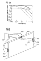
- the magnetic field strength H decreases with increasing distance from a current-carrying conductor or the current-carrying cylindrical coil 200. If, for example, a measuring point is removed from the center of the coil 200 in the direction of the coil axis (x-axis), the field strength H of the magnetic field will decrease continuously with the distance x. This relationship is illustrated by way of example in FIG. 2b.
- Fig. 2b shows in a logarithmic representation schematically a curve of the magnetic field strength H in a vicinity of the current-carrying cylindrical coil 200 with increasing distance in the x-direction, i. in the direction of the coil longitudinal axis.
- the curve with the reference numeral 210 exemplarily designates a field strength course with a relatively large radius R of the windings of the coil 200.
- the curve with the reference numeral 220 correspondingly denotes a profile of the magnetic field strength H at a mean winding radius R.
- the curve with reference number 230 means a schematic field strength curve at a small winding radius R of the coil 200th
- the field intensity drop in the so-called near field of the coil is initially approximately 60 dB per decade, and then flattened to 20 dB per decade in the far field with a developing electromagnetic wave.
- the field strength H depends on the radius (or area) of the coil 200 up to a certain distance x almost constant, but then drops.
- the magnetic field strength curves illustrated in FIG. 2b relate to a near zone of the cylindrical coil 200, ie a region around the cylindrical coil 200 of a few meters. Thus, it is possible to assign a distance x from the cylindrical coil 200 to each magnetic field H.
- H I ⁇ N ⁇ R 2 2 ⁇ R 2 + x 2 3 .
- N the number of coil turns
- R the winding radius
- x the distance to the coil center in the x direction.
- Equation (1) is merely illustrative of the dependence of the magnetic field strength on the distance from a magnetic antenna or coil. Equally, equations can be established that describe a field strength course around a coil in three-dimensional space. In addition to an amount of the magnetic field strength H, there is also an alignment or orientation of a magnetic field vector H , Be the three components (H x , H y , H z ) of the magnetic field vector H measured at the location of the moving object, it can be determined according to an embodiment of the present invention with an equation system, the space coordinates (x, y, z) of the location at which the magnetic field vector H was measured. In order to exclude ambiguities, measurements of the magnetic field vector are generally required H of several coils.
- the magnetic field generated by the coil 200 three-dimensionally with a desired accuracy in a localization area around the coil 200 and the measured values or components (H x , H y , H z ) of the field vector H for each relevant point in space, for example in a so-called look-up table, to associate and store the respective spatial coordinates (x, y, z) of the spatial points.
- the field strengths and field directions are calculated according to a further embodiment of the present invention in a region of interest around the coil by means of mathematical formulas, and then assigned in a lookup table the corresponding coordinates (x, y, z) to become.
- the measurements can then be compared to the pre-measured or calculated and stored values from the look-up table.
- the record that has the best hits finally indicates the location of the measurement.
- (H x 2 + H y 2 + H z 2 ) 1/2 provide information about the position of the moving object in the location determination area.
- ambiguities arise with respect to the position, since curves or surfaces exist around the coils, on which the magnitude of the measured magnetic field vector
- This principle is now utilized according to exemplary embodiments of the present invention in order to be able to determine, for example, a position of a mobile object by means of magnetic fields.
- a position of a mobile object by means of magnetic fields.
- one of the most controversial topics is whether in critical situations the ball has crossed the goal line or not. For this it is necessary that the position of the ball at the goal line can be measured with an accuracy of approx. +/- 1.5 cm.
- An arrangement which enables a position determination of a football by means of magnetic fields is shown schematically in FIG.
- FIG. 3 shows a device 100 for driving three coils 200a-c, which are respectively arranged in the two goal posts 300a, b and in a crossbar 300c of a soccer goal 300.
- the soccer goal 300 is located on a goal line 310.
- a movable object 320 In a region in front of the soccer goal 300 is a movable object 320 whose position is to be determined.
- the three coils are actuated sequentially by the device 100 according to one exemplary embodiment of the present invention, ie, only one of the three coils 200a-c is active in a first time period T 1 , a second of the three coils 200a is activated in a second time period T 2 . c is active and in a third time period T 3, the third of the three coils 200a-c is active.
- the respective field strengths (amounts of the magnetic field vectors) and their directions belonging to the coil fields are measured at the location of the ball 320 and subsequently used to be able to carry out a location determination for the soccer ball 320 by means of a system of equations.
- the magnetic fields generated by the coils 200a-c should each be static during the measurements.
- a superposition of the geomagnetic field is also taken into account.
- the Earth's magnetic field is the magnetic field surrounding the Earth. It is generated by the so-called geodynamo. Above the earth's surface, the field has a shape similar to that of a magnetic dipole. The magnetic field lines emerge from the core essentially in the southern hemisphere and back into the nucleus through the northern hemisphere.
- the Earth's magnetic field is largely static. It is roughly oriented in geographic north-south direction on large parts of the earth's surface, which is why a compass needle in these areas points approximately to the north.
- the strength of the Earth's magnetic field is relatively small at about 20 - 30 microtesla at the Earth's surface.
- the Earth's magnetic field is not parallel to the earth's surface, but enters the surface at an angle of inclination.
- a measurement cycle according to an exemplary embodiment of the present invention for determining the position of the ball 320 is shown by way of example in FIG. 4.
- 4 shows a flow chart of the measuring cycle with steps S1 to S6.
- a magnetic field sensor in the ball 320 measures the magnitude and direction of the earth's magnetic field relative to the ball 320.
- a first of the three coils 200a-c is energized, for example, coil 200a.
- the magnetic field sensor in the ball 320 measures the magnitude and direction of the combination of the magnetic field generated by the coil 200a with the earth's magnetic field. The measurement is carried out in the time in which the magnetic field of the coil is constant or static. During the assembly and disassembly of the magnetic field of the coil 200a, no measurements are made.
- step S3 After the measurement of step S3 has been completed, the current in the coil is reversed in a step S4 and the measurement is repeated, ie the magnetic field sensor in the ball 320 measures in step S5 the strength and the direction of the combination of that produced by the coil 200a, reversed magnetic field with the Earth's magnetic field.
- the magnetic field sensor in the ball 320 measures in step S5 the strength and the direction of the combination of that produced by the coil 200a, reversed magnetic field with the Earth's magnetic field.
- step S5 A combination of the two measurements of steps S3 and S5 makes it possible to calculate an effect of the earth's magnetic field.
- the measuring cycle for the first coil 200a is finished, and the steps S1-S5 are repeated for a next one of the remaining coils 200b, c, etc.
- the earth magnetic field is always measured between the measurements of the coil fields.
- the position of the ball 320 can be determined in a step S6 on the basis of the measurement results of the steps S1 to S5. This can be done, for example, by solving a system of equations, or by correlating the measurement results with stored calibration data.
- a football can reach speeds of up to 140 km / h, ie approx. 40 m / s, in certain situations in a soccer game. If a measurement accuracy of approximately +/- 1.5 cm is required, then preferably the entire measurement cycle, including all coils 200a-c, should occur within a period of approximately 375 ⁇ s. If this period is divided among the various coils used, for example, for a three-coil system, as shown in Fig. 3, there are approximately 125 ⁇ s per measurement and coil available for measurement.
- R Sp is, for example, the conductor resistance of the coil and L is the inductance of the coil.
- a reversal of the current through a coil within a short time can thus be ensured, for example, by a correspondingly high supply voltage of the coil, by a low inductance L, or by a low conductor resistance R Sp .
- FIG. 5 shows a football goal 300 comprising a first post 300a, a second post 300b and a crossbar 300c.
- the soccer goal 300 has a net suspension with a first post 300d, a second post 300e and a crossbar 300f.
- the soccer goal 300 stands with its posts 300a, 300b on a goal line 310.
- the goal posts 300a, b, the crossbar 300c and the goal line 310 form a frame of a rectangular coil 200a, which according to an embodiment of the present invention in the goal posts 300a, b, in the crossbar 300c and below the goal line 310 is wound around the gate opening surface.
- a coil 200b at least approximately identical to the coil 200a is wound within the net suspension posts 300d, e, the net suspension crossbar 300f, and below the surface of the earth.
- the two coils 200a, b thus form, according to an embodiment of the present invention, a coil pair similar to a Helmholtz coil pair.
- FIG. 5 shows a movable object or ball in an area in front of the soccer goal 300 320 whose position is to be determined.
- FIG. 5 shows a device 100 for driving the two coils 200a, b.
- the two coils 200a, b can be driven in a multiplexing process.
- this may be a time-division multiplex method, that is to say a temporally sequential control of the two coils 200a, b, as already described with reference to the flowchart shown in FIG.
- the magnetic field of a rectangular coil, as shown in FIG. 5, is generally not homogeneous within the coil, as illustrated in FIG.
- Fig. 6 shows a plan view of the gate opening area of the coil 200a.
- the lines indicated by the reference numeral 600 schematically indicate a field strength distribution within the rectangular coil 200a.
- a small distance of second adjacent lines 600 means a comparatively high field strength of the magnetic field at the corresponding position
- a large distance between two lines 600 means a comparatively small amount of the magnetic field strength within the coil 200a.
- 6 shows that, in particular in the corner regions of the coil 200a, larger magnetic field strengths prevail than in the middle of the coil 200a. This fact can also be demonstrated analytically with the law of Biot-Savart, for example.
- a contribution d H an infinitesimal conductor piece d passed through by a current I d H to the magnetic field H in a point P according to d ⁇ H ⁇ r ⁇ I ⁇ d ⁇ l ⁇ ⁇ r ⁇ 4 ⁇ ⁇ ⁇ r 3 to calculate.
- the second coil 200b behind the football goal 300 in the net suspension is advantageous.
- an isolated measurement of the magnetic field generated by the second coil 200b in a second period of time at the location of the ball or moving object 320 enough information can be obtained in combination with the isolated measurement of that from the first coil 200a in a first Time generated Magnetic field to determine an exact position of the ball 320.
- FIG. 1 Another embodiment of the present invention is shown in FIG. 1
- FIG. 7 shows a plan view of a soccer goal 300 standing on a goal line 310.
- Behind the goal line 310 is a first coil 200a and a second coil 200b.
- the coil axes of the two coils 200a, b show at least approximately in the direction of the playing field.
- the two coils are driven by a device, not shown in FIG. 7, for driving the two coils, as has already been described above.
- the two coils 200a, b can be controlled both in a time division multiplex method and in a frequency division multiplex method.
- a ball 320 which is located in the location determination region of the two coils 200a, b, can measure magnetic field vectors of the magnetic field generated by the first coil 200a and the magnetic field generated by the second coil 200b by means of a three-dimensional magnetic field sensor, and transmit them, for example, to a central evaluation device ,
- the position determination can also in the embodiment of the present invention shown in FIG Invention according to the method described with reference to FIG. 4.
- An advantage of the embodiment of the present invention shown in FIG. 7 is that the arrangement of the two coils 200 a, b makes it possible to clearly determine whether the ball 320 is located in front of or behind the goal line 310.
- the multiplexing method may also be a frequency division multiplexing, ie a frequency-different generation of alternating magnetic fields by corresponding control of the two coils 200a, b.
- the coils 200a, b of the device 100 for driving the coils can thus be driven with different frequencies f 1 and f 2 .
- Fig. 8 shows a moving object 320 for localization at a location determining area in which at least two coils (not shown) arranged at different positions with respect to the locating area are driven in accordance with a control sequence.
- the moving object 320 includes a magnetic field sensor 800 coupled to a controller 810. Furthermore, the control device 810 is connected to a transmitter 820.
- the magnetic field sensor 800 serves to detect a magnetic field in which the movable object 320 is located.
- it may be a three-dimensional magnetic field sensor in which, for example, a Digitization of the measured values on a sensor chip is already integrated.
- the control device 810 serves to control the magnetic field sensor 800 and / or the transmitter 820, so that, for example, according to the control sequence from FIG. 4, magnetic field measurements can be sent to a central computer, not shown in FIG.
- the transmitter 820 may allow the transmission of at least one measured value and be designed, for example, as a radio transmitter in order not to have to intervene in the game mode during a football game for data evaluation.
- the transmitter 820 can also have a data interface in order to be able to read measured values stored in a memory of the movable object 320, not shown in FIG. 8, by means of a wired connection.
- the moving object 320 needs a power supply device for powering the moving object 320.
- a power supply by a battery can be ensured.
- the measured values can be transmitted by radio from the mobile object or the ball 320, for example to a central computer or device for determining information about the position of the mobile object 320, where the instantaneous position , a rotation and a speed of the ball 320 can be calculated on the basis of the transmitted magnetic field measured values.
- 9 shows a schematic block diagram of a device for determining information about the position of the moving object 320 in a location determining area in which at least two coils are arranged at different positions which are driven in accordance with a control sequence to respectively generate a magnetic field by a multiplexing method.
- FIG. 9 shows a device 900 for determining information about the position of the movable object or the ball 320, the device 900 having a receiver 910 which is coupled to an evaluation device 920.
- the receiver 910 may be a radio receiver. It should be noted that the receiver 910 could also have an interface to be coupled to the mobile object 320, for example by wire, in order to be able to read the measured values of the magnetic fields.
- the device 900 for determining information about the position of the movable object or the ball 320 comprises a filter device, in particular a bandpass filter device, for the magnetic field measured values transmitted by the ball 320 each to be able to assign the at least two coils 200a, b.
- a filter device in particular a bandpass filter device
- Has a band-pass filter has a passband around the frequency f 1 of the alternating magnetic field of the first coil 200a, the magnetic field readings can hereby be filtered out, which can be assigned to the first coil 200a.
- the evaluation device 920 is designed to obtain the information about the position of the moving object 320 by solving a system of equations in which the sequence of measured values of the magnetic fields with respect to the at least two coils is used.
- the evaluation device 920 may also be configured to obtain the information about the position of the moving object 320 by comparing the measured values of the sequence of measured values of the magnetic fields with predetermined values, the positions of the moving object 320 in the location determination area. For this purpose, for example, the field strengths and the field directions of the individual coil fields in the goal area can be calculated or measured in advance. The measured values of the ball 320 are then compared with these calculated or measured values. The record that has the best hits finally designates the location of the ball 320.
- An accuracy of the position determination can be increased according to an embodiment of the present invention by combining the measurements of the magnetic field strengths with the measurements of the associated field directions. Thus, for example, a plausibility check can take place and ambiguities can be excluded.
- the rotational speed of the ball or the moving object 320th be determined and determined by means of previously determined position values, a ball speed and a direction of flight. This information, along with other known physical properties of the ball 320, may allow for additional error correction for subsequent measurements or position determinations.
- the device 900 After the location of the movable object or the ball 320 has been calculated by the evaluation device 920, it is checked, for example, whether the ball 320 has crossed the goal line. For this purpose, known coordinates of the goal line can be used. If the device 900 detects a "gate" event, the device 900 according to an exemplary embodiment of the present invention can also be designed to transmit a corresponding signal, for example by radio, to a watch of a referee.
- FIG. 10 has exemplary embodiments of the system components according to the invention described above.
- FIG. 10 shows a soccer goal 300 comprising a first post 300a, a second post 300b and a crossbar 300c. Furthermore, the football goal 300 has a first net suspension 300d and a second net suspension 300e.
- the first post 300a has a first coil 200a
- the second post 300b has a second coil 200b
- the crossbar 300c has a third coil 200c
- the first net suspension 300d has a fourth coil 200d
- the second net suspension 300e has a fifth one Coil 200e on.
- FIG. 10 shows a ball 320 located in the goal area or in the location determination area and having a three-dimensional magnetic field sensor 800.
- the system shown in FIG. 10 has a central control and evaluation device 1000.
- Reference numeral 1010 denotes magnetic field lines emanating from the first coil 200a by way of example.
- the central control and evaluation device 1000 has a device 100 for controlling the coils 200a-e described with reference to FIG. 1, as well as a device 900 described with reference to FIG. 9 for determining information about the ball position.
- the determination of the positions of the ball 320 takes place, for example, according to the inventive method described with reference to FIG. 4, wherein in the embodiment of the present invention shown in FIG. 7 a total of five coils 200a-e are used.
- the frequency multiplexing method described above could also be used.
- using a larger number of coils may increase the accuracy of positioning the ball 320.
- the central control and evaluation apparatus 1000 includes means for communicating information about which coil of the five coils 200a-e is being driven by the coil activation signal generating means to provide temporal synchronization between the apparatus for generating coil activation signals and the measuring system of the ball 320.
- the transmission of the coil information could be done for example by means of a radio transmitter. Also conceivable is an encoding of the coil information by a specific drive sequence of the respective coils.
- the ball 320 in addition to the magnetic field measurement data, the ball 320 also transmits information about the respective coil corresponding to the magnetic field measurement data to the ball position information acquiring apparatus.
- a drive sequence for the coils may be predetermined such that the central control and evaluation apparatus 1000 need only have means for communicating information about a start of the drive sequence of the coil activation signals. If the ball 320 receives this start signal from the device, the magnetic field measurement in the ball takes place analogously to the drive sequence for the coils.
- the central control and evaluation device 1000 comprises a filter device, in particular a bandpass filter device, in order to be able to assign the magnetic field measured values transmitted by the ball 320 to the coils 200a-e.
- the field geometry of the respective magnetic fields is as undisturbed or physically ideal as possible.
- Possible influences on the field geometry are, for example, ferromagnetic objects in the vicinity of the gate 300, induced eddy currents by moving objects near the door or electrical systems, such as power cables, near the door.
- ferromagnetic objects eg the substructure for an extendable lawn in a football stadium
- a distortion of the magnetic field in the immediate vicinity of the goal line can be measured, for example with the aid of a so-called goal scanner become. Since these influences are static, these measured values can be taken into account in the location of the ball 320. This can be achieved, for example, by means of a correction table in a memory of the central control / evaluation device 1000.
- the central control / evaluation apparatus 1000 may comprise a ball position information determining device adapted to use differential magnetic field measurements for position detection, i. not only can it.
- absolute field strengths of the individual coils can be assigned to the magnetic fields are determined at the location of the moving object, but also differential magnetic fields or magnetic field differences between the individual coils assignable magnetic fields. By observing magnetic field differences at the location of the moving object, it is easier to neglect disturbing influences from the outside, for example.
- An influence on the magnetic fields generated by the coils 200a-e by power cables located in the vicinity of the coils 200a-e is relatively small.
- a power cable usually has a forward and a return conductor, so that cancel the magnetic fields of the forward and return conductors each other. Even with single conductors, the influence would be relatively low, since at a mains frequency of 50 Hz, the field effect would be equivalent to a slight change in the earth's magnetic field.
- this is already taken into account by the measuring method with polarity change of the magnetic fields generated by the coils 200a-e.
- the ball 320 may be activated near the door 300 via a weak signal sent from, for example, a transmitter of the central controller / evaluator 1000 configured therefor.
- the ball 320 according to an exemplary embodiment of the present invention has a receiver which receives the activation signal and then activates the measuring system in the ball in the vicinity of the gate 300 via the control device or a processor.
- the processor in the ball briefly turns on the receiver every 100 ms. Once the activation signal from the ball 320 is detected, the ball goes into continuous operation.
- a permanent magnetic field can be generated at the gate 300 or in the vicinity of the gate 300 via a coil. If the ball 320 comes close to the gate 300, this is detected by the three-dimensional magnetic field sensor 800 in the ball 320. As soon as this is the case, the measuring system switches on in the ball 320.
- the sensors can only be put into operation for a short time every 100 milliseconds.
- detection is always switched on only briefly in order to save energy. If the ball 320 no longer detects a signal for a very long time, for example one day, a timer for detection is raised, for example, to ten seconds. This can drastically reduce energy consumption once again. Since, according to an exemplary embodiment of the present invention, the state of a battery in the ball 320 can be interrogated, it is ensured that the timer in the ball 320 is again set to 100 milliseconds, for example, at the start of the game.
- the power supply in the ball 320 may be configured for, for example, 300 hours of active playtime.
- the life of the battery of the ball 320 may be designed, for example, to be three years.
- the energy supply of the ball 320 could of course also be done without a battery by means of accumulators, which can be charged, for example, by natural processes, such as light irradiation or movement. However, as indicated above, this would require relatively expensive charging techniques.
- An advantage of the inventive concept for position determination is that a position determination can be made very robust against intentional or unwanted influence.
- the movable object positioning system illustrated in FIG. 10 according to an embodiment of the present invention could be disturbed by interfering with a radio link between ball 320 and the central computer 1000.
- a receiving antenna is integrated in the control unit 1000 of the coils and thus can be located just behind the gate, a disruption of the system is very complex.
- the antenna can also be aligned, for example, as a directional antenna to the field.
- data transmission between the ball 320 and the central control unit 1000 according to an embodiment of the present invention is only active when the ball is very close to the goal, ie in the location determination area.
- a reception power of the radio link is very high due to the relatively short distance between ball 320 and control unit 1000. This would have a potential attacker a very use complex and thus with high probability not inconspicuous plant.
- the system can detect a malfunction and, for example, generate a warning if it succeeds in disturbing the system by radio or magnetic field.
- magnetic field sensors are fixedly mounted on the gate to monitor the magnetic fields generated by the coils 200a-e.
- the magnetic fields can be regulated, so that, for example, environmental influences (temperature can influence the coil resistance) or technical influences (for example sudden switching on of a lawn heater) can be corrected.
- the magnetic fields generated and used by the coils 200a-e are of the order of magnitude of the earth's magnetic field, it can be assumed that they have no biological effects. Also switching the Magnetic fields has no significant effects due to the sizes of the coils and thus the associated large area distribution of the magnetic field. For example, a punctual load by a mobile phone by many orders of magnitude higher.
- a further advantage of embodiments of the present invention is that the movable object or ball can have a low power consumption because it does not have to send a continuous location signal, as is necessary, for example, in radar systems or radio location systems.
- a system according to the invention is used, for example, for goal recognition in football, then no extensive installations in a football stadium are necessary. All necessary installations are only at the two respective gates. In addition, no calibration or calibration of antennas or cameras is necessary. In addition, there is no unnecessary system load from balls not involved in the game, since they can be switched off or are not within range of the magnetic fields generated in the goal area.
- an installation of a system according to the invention for determining the position of a moving object can take place at considerably lower costs in comparison to radio-based or optical systems.
- embodiments of the present invention thus provide a method for locating a ball by successive measurements of the field strengths of multiple coils, a method for locating a ball by successive measurements of the field directions of multiple coils, a method for increasing the accuracy by combining field strength measurements with field direction measurements and a method for increasing the accuracy by determining the rotational speed of the ball to better calculate the other trajectory.
- Further exemplary embodiments of the present invention include a method for measuring field distortions by means of a gate scanner, a method for determining the position by means of precalculated field strength and field directions in the plane of the goal line.
- embodiments of the present invention provide a method for activating the ball by means of radio waves, a method for activating the ball by means of a magnetic field and a method for energy saving by means of the activation technique and the dynamic scanning of the activating conditions.
- embodiments of the present invention include a method for Detection of intentional or unwanted influence on the system.
- the inventive scheme can also be implemented in software.
- the implementation may be on a digital storage medium, in particular a floppy disk or a CD with electronically readable control signals, which may cooperate with a programmable computer system and / or microcontroller such that the corresponding method is executed.
- the invention thus also consists in a computer program product with program code stored on a machine-readable carrier for carrying out the method according to the invention, when the computer program product runs on a computer and / or microcontroller.
- the invention can thus be realized as a computer program with a program code for carrying out the method, when the computer program runs on a computer and / or microcontroller.
Landscapes
- Health & Medical Sciences (AREA)
- General Health & Medical Sciences (AREA)
- Physical Education & Sports Medicine (AREA)
- Physics & Mathematics (AREA)
- General Physics & Mathematics (AREA)
- Engineering & Computer Science (AREA)
- Radar, Positioning & Navigation (AREA)
- Remote Sensing (AREA)
- Measurement Of Length, Angles, Or The Like Using Electric Or Magnetic Means (AREA)
Priority Applications (4)
| Application Number | Priority Date | Filing Date | Title |
|---|---|---|---|
| EP20060020009 EP1852155B1 (fr) | 2006-05-02 | 2006-09-25 | Système et procédé pour déterminer la position d'un objet mobile à l'aide de champs magnétiques |
| EP07724520A EP2021085A1 (fr) | 2006-05-02 | 2007-04-24 | Systeme et procédé de détermination de la position d'un objet en mouvement au moyen de champs magnétiques |
| PCT/EP2007/003590 WO2007128406A1 (fr) | 2006-05-02 | 2007-04-24 | Systeme et procédé de détermination de la position d'un objet en mouvement au moyen de champs magnétiques |
| US11/742,513 US7795861B2 (en) | 2006-05-02 | 2007-04-30 | Method and apparatus for controlling a movable object for localization within a positioning area |
Applications Claiming Priority (2)
| Application Number | Priority Date | Filing Date | Title |
|---|---|---|---|
| EP06009069 | 2006-05-02 | ||
| EP20060020009 EP1852155B1 (fr) | 2006-05-02 | 2006-09-25 | Système et procédé pour déterminer la position d'un objet mobile à l'aide de champs magnétiques |
Publications (2)
| Publication Number | Publication Date |
|---|---|
| EP1852155A1 true EP1852155A1 (fr) | 2007-11-07 |
| EP1852155B1 EP1852155B1 (fr) | 2012-01-11 |
Family
ID=38329226
Family Applications (2)
| Application Number | Title | Priority Date | Filing Date |
|---|---|---|---|
| EP20060020009 Not-in-force EP1852155B1 (fr) | 2006-05-02 | 2006-09-25 | Système et procédé pour déterminer la position d'un objet mobile à l'aide de champs magnétiques |
| EP07724520A Withdrawn EP2021085A1 (fr) | 2006-05-02 | 2007-04-24 | Systeme et procédé de détermination de la position d'un objet en mouvement au moyen de champs magnétiques |
Family Applications After (1)
| Application Number | Title | Priority Date | Filing Date |
|---|---|---|---|
| EP07724520A Withdrawn EP2021085A1 (fr) | 2006-05-02 | 2007-04-24 | Systeme et procédé de détermination de la position d'un objet en mouvement au moyen de champs magnétiques |
Country Status (2)
| Country | Link |
|---|---|
| EP (2) | EP1852155B1 (fr) |
| WO (1) | WO2007128406A1 (fr) |
Cited By (8)
| Publication number | Priority date | Publication date | Assignee | Title |
|---|---|---|---|---|
| DE102007015493A1 (de) * | 2007-03-30 | 2008-10-02 | Cairos Technologies Ag | Bewegungsbereich für einen mobilen Gegenstand und Auswertungsvorrichtung zum Feststellen einer Position eines mobilen Gegenstands |
| US8512177B2 (en) | 2009-11-19 | 2013-08-20 | Wilson Sporting Goods Co. | American-style football including improved bladder construction for mounting of electronics |
| WO2014090572A1 (fr) * | 2012-12-13 | 2014-06-19 | Fraunhofer-Gesellschaft zur Förderung der angewandten Forschung e.V. | Article d'équipement sportif déformable élastiquement comportant une structure de bobine électromagnétique déformable |
| US9636550B2 (en) | 2009-11-19 | 2017-05-02 | Wilson Sporting Goods Co. | Football sensing |
| WO2019096724A1 (fr) * | 2017-11-16 | 2019-05-23 | Fraunhofer-Gesellschaft zur Förderung der angewandten Forschung e.V. | Système et procédé de détermination d'un passage d'un objet mobile à travers une zone intéressante d'un niveau surveillé, et objets mobiles |
| US10668333B2 (en) | 2009-11-19 | 2020-06-02 | Wilson Sporting Goods Co. | Football sensing |
| US10751579B2 (en) | 2009-11-19 | 2020-08-25 | Wilson Sporting Goods Co. | Football sensing |
| US10821329B2 (en) | 2009-11-19 | 2020-11-03 | Wilson Sporting Goods Co. | Football sensing |
Citations (4)
| Publication number | Priority date | Publication date | Assignee | Title |
|---|---|---|---|---|
| DE2732543A1 (de) | 1977-07-19 | 1979-02-01 | Precitec Gmbh | Vorrichtung und verfahren zur ueberwachung einer grenzlinie |
| WO2000047291A1 (fr) * | 1999-02-09 | 2000-08-17 | Integrated Design Limited | Detection de position |
| US20030163037A1 (en) | 1992-08-14 | 2003-08-28 | British Telecommunications Public Limited Company | Surgical navigation |
| US6686881B1 (en) | 1999-11-30 | 2004-02-03 | International Business Machines Corporation | Wireless identification and tracking using magnetic fields |
-
2006
- 2006-09-25 EP EP20060020009 patent/EP1852155B1/fr not_active Not-in-force
-
2007
- 2007-04-24 EP EP07724520A patent/EP2021085A1/fr not_active Withdrawn
- 2007-04-24 WO PCT/EP2007/003590 patent/WO2007128406A1/fr not_active Ceased
Patent Citations (4)
| Publication number | Priority date | Publication date | Assignee | Title |
|---|---|---|---|---|
| DE2732543A1 (de) | 1977-07-19 | 1979-02-01 | Precitec Gmbh | Vorrichtung und verfahren zur ueberwachung einer grenzlinie |
| US20030163037A1 (en) | 1992-08-14 | 2003-08-28 | British Telecommunications Public Limited Company | Surgical navigation |
| WO2000047291A1 (fr) * | 1999-02-09 | 2000-08-17 | Integrated Design Limited | Detection de position |
| US6686881B1 (en) | 1999-11-30 | 2004-02-03 | International Business Machines Corporation | Wireless identification and tracking using magnetic fields |
Cited By (16)
| Publication number | Priority date | Publication date | Assignee | Title |
|---|---|---|---|---|
| DE102007015493A1 (de) * | 2007-03-30 | 2008-10-02 | Cairos Technologies Ag | Bewegungsbereich für einen mobilen Gegenstand und Auswertungsvorrichtung zum Feststellen einer Position eines mobilen Gegenstands |
| US10220264B2 (en) | 2009-11-19 | 2019-03-05 | Wilson Sporting Goods Co. | American-style football including electronics |
| US10398945B2 (en) | 2009-11-19 | 2019-09-03 | Wilson Sporting Goods Co. | Football sensing |
| US8870690B2 (en) | 2009-11-19 | 2014-10-28 | Wilson Sporting Goods Co. | American-style football including electronics |
| US8870689B2 (en) | 2009-11-19 | 2014-10-28 | Wilson Sporting Goods, Co. | American-style football including electronics coupled to the bladder |
| US9636550B2 (en) | 2009-11-19 | 2017-05-02 | Wilson Sporting Goods Co. | Football sensing |
| US9776047B2 (en) | 2009-11-19 | 2017-10-03 | Wilson Sporting Goods Co. | American-style football including electronics coupled to the bladder |
| US10821329B2 (en) | 2009-11-19 | 2020-11-03 | Wilson Sporting Goods Co. | Football sensing |
| US10238922B2 (en) | 2009-11-19 | 2019-03-26 | Wilson Sporting Goods Co. | American-style football including electronics |
| US10751579B2 (en) | 2009-11-19 | 2020-08-25 | Wilson Sporting Goods Co. | Football sensing |
| US10668333B2 (en) | 2009-11-19 | 2020-06-02 | Wilson Sporting Goods Co. | Football sensing |
| US8512177B2 (en) | 2009-11-19 | 2013-08-20 | Wilson Sporting Goods Co. | American-style football including improved bladder construction for mounting of electronics |
| US10463921B2 (en) | 2009-11-19 | 2019-11-05 | Wilson Sporting Goods Co. | American-style football including electronics |
| US9889343B2 (en) | 2012-12-13 | 2018-02-13 | Fraunhofer-Gesellschaft Zue Foerderung Der Angewandten Forschung E.V. | Elastically deformable item of sports equipment comprising a deformable electromagnetic coil structure |
| WO2014090572A1 (fr) * | 2012-12-13 | 2014-06-19 | Fraunhofer-Gesellschaft zur Förderung der angewandten Forschung e.V. | Article d'équipement sportif déformable élastiquement comportant une structure de bobine électromagnétique déformable |
| WO2019096724A1 (fr) * | 2017-11-16 | 2019-05-23 | Fraunhofer-Gesellschaft zur Förderung der angewandten Forschung e.V. | Système et procédé de détermination d'un passage d'un objet mobile à travers une zone intéressante d'un niveau surveillé, et objets mobiles |
Also Published As
| Publication number | Publication date |
|---|---|
| WO2007128406A1 (fr) | 2007-11-15 |
| EP1852155B1 (fr) | 2012-01-11 |
| EP2021085A1 (fr) | 2009-02-11 |
Similar Documents
| Publication | Publication Date | Title |
|---|---|---|
| DE102007009232B3 (de) | Vorrichtung und Verfahren zum Erzeugen eines Magnetfeldes in einem Torraum zur Torentscheidung | |
| DE102006047376B3 (de) | Konzept zur Torentscheidung mittels Magnetfeldern | |
| US7795861B2 (en) | Method and apparatus for controlling a movable object for localization within a positioning area | |
| DE3012616C2 (de) | Flughafenüberwachungseinrichtung | |
| DE102007015493A1 (de) | Bewegungsbereich für einen mobilen Gegenstand und Auswertungsvorrichtung zum Feststellen einer Position eines mobilen Gegenstands | |
| DE102014207253B4 (de) | Vorrichtung zum Überprüfen eines Vorhandenseins eines elektrisch leitfähigen Körpers und Ladeanordnung zum induktiven Laden eines Elektrofahrzeugs | |
| WO1996011414A1 (fr) | Systeme de detection pour detecter, localiser et identifier des objets metalliques | |
| EP1852155B1 (fr) | Système et procédé pour déterminer la position d'un objet mobile à l'aide de champs magnétiques | |
| DE102012017390A1 (de) | Spulenanordnung zum Erzeugen eines rotierenden elektromagnetischen Felds und Ortungssystem zum Bestimmen einer Position eines Identifikationsgebers | |
| DE102014215350A1 (de) | Spulenüberdeckung | |
| DE102010060571B3 (de) | Verfahren und Anordnung zur Erfassung von Passierzeiten an Kontrollstellen, insbesondere bei Sportveranstaltungen | |
| DE102012017387A1 (de) | Verfahren zum Bestimmen einer Position eines Empfängers und Ortungssystem für einen Empfänger | |
| EP1976601B1 (fr) | Concept lié à l'activation d'un article de jeu | |
| EP2635998A1 (fr) | Appareil mobile et système d'infrastructure | |
| DE102011050926A1 (de) | System zur Erfassung der Position eines Gegenstandes | |
| DE102010048917B4 (de) | Wirbelstromflächensensor | |
| DE102016120246A1 (de) | Verfahren, Vorrichtung und Computerprogramm zum Bestimmen einer Information über eine Position eines Objekts, wobei das Objekt ein Magnetfeld emittiert | |
| DE4313773C1 (de) | Verfahren zur Überwachung eines Gebietes mittels Fremdpotentialmessung | |
| WO2016207073A1 (fr) | Dispositif et procédé de détection d'un objet | |
| WO2004014774A1 (fr) | Dispositif de transport de personnes comprenant une main courante avec transpondeur integre | |
| EP0829736A2 (fr) | Procédé de mesure des distorsions de champ magnétique terrestre et capteur d'objet pour la mise en oeuvre du procédé | |
| DE4030882C1 (en) | Electrical and magnetic fields insensitive continuous plating plant - has forked sensor head to position strip edge, arms to mount AC transmitter and parallelly connected receiver coils | |
| CH627836A5 (en) | Arrangement for automatic length measurement in ski jumping | |
| DE102007008854A1 (de) | System und Verfahren zum Täuschen eines Positionsbestimmungssystems | |
| DE102012015200A1 (de) | Induktiver Näherungsschalter |
Legal Events
| Date | Code | Title | Description |
|---|---|---|---|
| PUAI | Public reference made under article 153(3) epc to a published international application that has entered the european phase |
Free format text: ORIGINAL CODE: 0009012 |
|
| AK | Designated contracting states |
Kind code of ref document: A1 Designated state(s): AT BE BG CH CY CZ DE DK EE ES FI FR GB GR HU IE IS IT LI LT LU LV MC NL PL PT RO SE SI SK TR |
|
| AX | Request for extension of the european patent |
Extension state: AL BA HR MK YU |
|
| RIN1 | Information on inventor provided before grant (corrected) |
Inventor name: ENGLERT, WALTER |
|
| 17P | Request for examination filed |
Effective date: 20080506 |
|
| 17Q | First examination report despatched |
Effective date: 20080613 |
|
| AKX | Designation fees paid |
Designated state(s): AT BE BG CH CY CZ DE DK EE ES FI FR GB GR HU IE IS IT LI LT LU LV MC NL PL PT RO SE SI SK TR |
|
| R17C | First examination report despatched (corrected) |
Effective date: 20080711 |
|
| GRAP | Despatch of communication of intention to grant a patent |
Free format text: ORIGINAL CODE: EPIDOSNIGR1 |
|
| GRAS | Grant fee paid |
Free format text: ORIGINAL CODE: EPIDOSNIGR3 |
|
| GRAA | (expected) grant |
Free format text: ORIGINAL CODE: 0009210 |
|
| AK | Designated contracting states |
Kind code of ref document: B1 Designated state(s): AT BE BG CH CY CZ DE DK EE ES FI FR GB GR HU IE IS IT LI LT LU LV MC NL PL PT RO SE SI SK TR |
|
| REG | Reference to a national code |
Ref country code: GB Ref legal event code: FG4D Free format text: NOT ENGLISH |
|
| REG | Reference to a national code |
Ref country code: CH Ref legal event code: EP |
|
| REG | Reference to a national code |
Ref country code: AT Ref legal event code: REF Ref document number: 540731 Country of ref document: AT Kind code of ref document: T Effective date: 20120115 |
|
| REG | Reference to a national code |
Ref country code: IE Ref legal event code: FG4D |
|
| REG | Reference to a national code |
Ref country code: DE Ref legal event code: R096 Ref document number: 502006010826 Country of ref document: DE Effective date: 20120315 |
|
| REG | Reference to a national code |
Ref country code: ES Ref legal event code: FG2A Ref document number: 2377989 Country of ref document: ES Kind code of ref document: T3 Effective date: 20120403 |
|
| REG | Reference to a national code |
Ref country code: NL Ref legal event code: VDEP Effective date: 20120111 |
|
| PG25 | Lapsed in a contracting state [announced via postgrant information from national office to epo] |
Ref country code: SI Free format text: LAPSE BECAUSE OF FAILURE TO SUBMIT A TRANSLATION OF THE DESCRIPTION OR TO PAY THE FEE WITHIN THE PRESCRIBED TIME-LIMIT Effective date: 20120111 |
|
| LTIE | Lt: invalidation of european patent or patent extension |
Effective date: 20120111 |
|
| PG25 | Lapsed in a contracting state [announced via postgrant information from national office to epo] |
Ref country code: NL Free format text: LAPSE BECAUSE OF FAILURE TO SUBMIT A TRANSLATION OF THE DESCRIPTION OR TO PAY THE FEE WITHIN THE PRESCRIBED TIME-LIMIT Effective date: 20120111 Ref country code: LT Free format text: LAPSE BECAUSE OF FAILURE TO SUBMIT A TRANSLATION OF THE DESCRIPTION OR TO PAY THE FEE WITHIN THE PRESCRIBED TIME-LIMIT Effective date: 20120111 Ref country code: BG Free format text: LAPSE BECAUSE OF FAILURE TO SUBMIT A TRANSLATION OF THE DESCRIPTION OR TO PAY THE FEE WITHIN THE PRESCRIBED TIME-LIMIT Effective date: 20120411 Ref country code: IS Free format text: LAPSE BECAUSE OF FAILURE TO SUBMIT A TRANSLATION OF THE DESCRIPTION OR TO PAY THE FEE WITHIN THE PRESCRIBED TIME-LIMIT Effective date: 20120511 |
|
| REG | Reference to a national code |
Ref country code: IE Ref legal event code: FD4D |
|
| PG25 | Lapsed in a contracting state [announced via postgrant information from national office to epo] |
Ref country code: GR Free format text: LAPSE BECAUSE OF FAILURE TO SUBMIT A TRANSLATION OF THE DESCRIPTION OR TO PAY THE FEE WITHIN THE PRESCRIBED TIME-LIMIT Effective date: 20120412 Ref country code: FI Free format text: LAPSE BECAUSE OF FAILURE TO SUBMIT A TRANSLATION OF THE DESCRIPTION OR TO PAY THE FEE WITHIN THE PRESCRIBED TIME-LIMIT Effective date: 20120111 Ref country code: PL Free format text: LAPSE BECAUSE OF FAILURE TO SUBMIT A TRANSLATION OF THE DESCRIPTION OR TO PAY THE FEE WITHIN THE PRESCRIBED TIME-LIMIT Effective date: 20120111 Ref country code: LV Free format text: LAPSE BECAUSE OF FAILURE TO SUBMIT A TRANSLATION OF THE DESCRIPTION OR TO PAY THE FEE WITHIN THE PRESCRIBED TIME-LIMIT Effective date: 20120111 Ref country code: PT Free format text: LAPSE BECAUSE OF FAILURE TO SUBMIT A TRANSLATION OF THE DESCRIPTION OR TO PAY THE FEE WITHIN THE PRESCRIBED TIME-LIMIT Effective date: 20120511 |
|
| PG25 | Lapsed in a contracting state [announced via postgrant information from national office to epo] |
Ref country code: CY Free format text: LAPSE BECAUSE OF FAILURE TO SUBMIT A TRANSLATION OF THE DESCRIPTION OR TO PAY THE FEE WITHIN THE PRESCRIBED TIME-LIMIT Effective date: 20120111 |
|
| PG25 | Lapsed in a contracting state [announced via postgrant information from national office to epo] |
Ref country code: RO Free format text: LAPSE BECAUSE OF FAILURE TO SUBMIT A TRANSLATION OF THE DESCRIPTION OR TO PAY THE FEE WITHIN THE PRESCRIBED TIME-LIMIT Effective date: 20120111 Ref country code: EE Free format text: LAPSE BECAUSE OF FAILURE TO SUBMIT A TRANSLATION OF THE DESCRIPTION OR TO PAY THE FEE WITHIN THE PRESCRIBED TIME-LIMIT Effective date: 20120111 Ref country code: IE Free format text: LAPSE BECAUSE OF FAILURE TO SUBMIT A TRANSLATION OF THE DESCRIPTION OR TO PAY THE FEE WITHIN THE PRESCRIBED TIME-LIMIT Effective date: 20120111 Ref country code: SE Free format text: LAPSE BECAUSE OF FAILURE TO SUBMIT A TRANSLATION OF THE DESCRIPTION OR TO PAY THE FEE WITHIN THE PRESCRIBED TIME-LIMIT Effective date: 20120111 Ref country code: CZ Free format text: LAPSE BECAUSE OF FAILURE TO SUBMIT A TRANSLATION OF THE DESCRIPTION OR TO PAY THE FEE WITHIN THE PRESCRIBED TIME-LIMIT Effective date: 20120111 Ref country code: DK Free format text: LAPSE BECAUSE OF FAILURE TO SUBMIT A TRANSLATION OF THE DESCRIPTION OR TO PAY THE FEE WITHIN THE PRESCRIBED TIME-LIMIT Effective date: 20120111 |
|
| PLBE | No opposition filed within time limit |
Free format text: ORIGINAL CODE: 0009261 |
|
| STAA | Information on the status of an ep patent application or granted ep patent |
Free format text: STATUS: NO OPPOSITION FILED WITHIN TIME LIMIT |
|
| PG25 | Lapsed in a contracting state [announced via postgrant information from national office to epo] |
Ref country code: SK Free format text: LAPSE BECAUSE OF FAILURE TO SUBMIT A TRANSLATION OF THE DESCRIPTION OR TO PAY THE FEE WITHIN THE PRESCRIBED TIME-LIMIT Effective date: 20120111 |
|
| 26N | No opposition filed |
Effective date: 20121012 |
|
| REG | Reference to a national code |
Ref country code: DE Ref legal event code: R097 Ref document number: 502006010826 Country of ref document: DE Effective date: 20121012 |
|
| BERE | Be: lapsed |
Owner name: CAIROS TECHNOLOGIES A.G. Effective date: 20120930 |
|
| PG25 | Lapsed in a contracting state [announced via postgrant information from national office to epo] |
Ref country code: MC Free format text: LAPSE BECAUSE OF NON-PAYMENT OF DUE FEES Effective date: 20120930 |
|
| REG | Reference to a national code |
Ref country code: CH Ref legal event code: PL |
|
| PG25 | Lapsed in a contracting state [announced via postgrant information from national office to epo] |
Ref country code: BE Free format text: LAPSE BECAUSE OF NON-PAYMENT OF DUE FEES Effective date: 20120930 Ref country code: LI Free format text: LAPSE BECAUSE OF NON-PAYMENT OF DUE FEES Effective date: 20120930 Ref country code: CH Free format text: LAPSE BECAUSE OF NON-PAYMENT OF DUE FEES Effective date: 20120930 |
|
| PGFP | Annual fee paid to national office [announced via postgrant information from national office to epo] |
Ref country code: DE Payment date: 20130927 Year of fee payment: 8 Ref country code: ES Payment date: 20130911 Year of fee payment: 8 |
|
| REG | Reference to a national code |
Ref country code: AT Ref legal event code: MM01 Ref document number: 540731 Country of ref document: AT Kind code of ref document: T Effective date: 20120925 |
|
| PGFP | Annual fee paid to national office [announced via postgrant information from national office to epo] |
Ref country code: GB Payment date: 20130925 Year of fee payment: 8 |
|
| PGFP | Annual fee paid to national office [announced via postgrant information from national office to epo] |
Ref country code: IT Payment date: 20130920 Year of fee payment: 8 |
|
| PG25 | Lapsed in a contracting state [announced via postgrant information from national office to epo] |
Ref country code: AT Free format text: LAPSE BECAUSE OF NON-PAYMENT OF DUE FEES Effective date: 20120925 |
|
| PGFP | Annual fee paid to national office [announced via postgrant information from national office to epo] |
Ref country code: FR Payment date: 20130920 Year of fee payment: 8 |
|
| PG25 | Lapsed in a contracting state [announced via postgrant information from national office to epo] |
Ref country code: TR Free format text: LAPSE BECAUSE OF FAILURE TO SUBMIT A TRANSLATION OF THE DESCRIPTION OR TO PAY THE FEE WITHIN THE PRESCRIBED TIME-LIMIT Effective date: 20120111 |
|
| PG25 | Lapsed in a contracting state [announced via postgrant information from national office to epo] |
Ref country code: LU Free format text: LAPSE BECAUSE OF NON-PAYMENT OF DUE FEES Effective date: 20120925 |
|
| PG25 | Lapsed in a contracting state [announced via postgrant information from national office to epo] |
Ref country code: HU Free format text: LAPSE BECAUSE OF FAILURE TO SUBMIT A TRANSLATION OF THE DESCRIPTION OR TO PAY THE FEE WITHIN THE PRESCRIBED TIME-LIMIT Effective date: 20060925 |
|
| REG | Reference to a national code |
Ref country code: DE Ref legal event code: R119 Ref document number: 502006010826 Country of ref document: DE |
|
| GBPC | Gb: european patent ceased through non-payment of renewal fee |
Effective date: 20140925 |
|
| REG | Reference to a national code |
Ref country code: FR Ref legal event code: ST Effective date: 20150529 |
|
| PG25 | Lapsed in a contracting state [announced via postgrant information from national office to epo] |
Ref country code: GB Free format text: LAPSE BECAUSE OF NON-PAYMENT OF DUE FEES Effective date: 20140925 Ref country code: DE Free format text: LAPSE BECAUSE OF NON-PAYMENT OF DUE FEES Effective date: 20150401 |
|
| PG25 | Lapsed in a contracting state [announced via postgrant information from national office to epo] |
Ref country code: IT Free format text: LAPSE BECAUSE OF NON-PAYMENT OF DUE FEES Effective date: 20140925 Ref country code: FR Free format text: LAPSE BECAUSE OF NON-PAYMENT OF DUE FEES Effective date: 20140930 |
|
| REG | Reference to a national code |
Ref country code: ES Ref legal event code: FD2A Effective date: 20151028 |
|
| PG25 | Lapsed in a contracting state [announced via postgrant information from national office to epo] |
Ref country code: ES Free format text: LAPSE BECAUSE OF NON-PAYMENT OF DUE FEES Effective date: 20140926 |