EP1852191B1 - Vorrichtung und Verfahren zur Stabilisierung von Werkstücken während eines Reinigungsvorgangs - Google Patents
Vorrichtung und Verfahren zur Stabilisierung von Werkstücken während eines Reinigungsvorgangs Download PDFInfo
- Publication number
- EP1852191B1 EP1852191B1 EP07008581A EP07008581A EP1852191B1 EP 1852191 B1 EP1852191 B1 EP 1852191B1 EP 07008581 A EP07008581 A EP 07008581A EP 07008581 A EP07008581 A EP 07008581A EP 1852191 B1 EP1852191 B1 EP 1852191B1
- Authority
- EP
- European Patent Office
- Prior art keywords
- workpieces
- stabilizers
- workpiece
- stabilizing
- distance
- Prior art date
- Legal status (The legal status is an assumption and is not a legal conclusion. Google has not performed a legal analysis and makes no representation as to the accuracy of the status listed.)
- Active
Links
- 238000004140 cleaning Methods 0.000 title claims abstract description 74
- 238000000034 method Methods 0.000 title claims abstract description 55
- 230000003019 stabilising effect Effects 0.000 title 1
- 230000000087 stabilizing effect Effects 0.000 claims abstract description 92
- 239000004033 plastic Substances 0.000 claims abstract description 7
- XEEYBQQBJWHFJM-UHFFFAOYSA-N Iron Chemical compound [Fe] XEEYBQQBJWHFJM-UHFFFAOYSA-N 0.000 claims abstract description 6
- 229910000831 Steel Inorganic materials 0.000 claims abstract description 5
- 239000000835 fiber Substances 0.000 claims abstract description 5
- 239000000463 material Substances 0.000 claims abstract description 5
- 239000010959 steel Substances 0.000 claims abstract description 5
- 229910052782 aluminium Inorganic materials 0.000 claims abstract description 3
- XAGFODPZIPBFFR-UHFFFAOYSA-N aluminium Chemical compound [Al] XAGFODPZIPBFFR-UHFFFAOYSA-N 0.000 claims abstract description 3
- 229910052742 iron Inorganic materials 0.000 claims abstract description 3
- 239000003381 stabilizer Substances 0.000 claims description 70
- 238000005422 blasting Methods 0.000 claims description 53
- 230000003213 activating effect Effects 0.000 claims description 3
- 229920002994 synthetic fiber Polymers 0.000 claims description 2
- OKTJSMMVPCPJKN-UHFFFAOYSA-N Carbon Chemical compound [C] OKTJSMMVPCPJKN-UHFFFAOYSA-N 0.000 claims 1
- 239000004411 aluminium Substances 0.000 claims 1
- 229910052799 carbon Inorganic materials 0.000 claims 1
- 230000008021 deposition Effects 0.000 claims 1
- 229920000049 Carbon (fiber) Polymers 0.000 abstract description 2
- 239000004917 carbon fiber Substances 0.000 abstract description 2
- CURLTUGMZLYLDI-UHFFFAOYSA-N Carbon dioxide Chemical compound O=C=O CURLTUGMZLYLDI-UHFFFAOYSA-N 0.000 description 27
- 230000006641 stabilisation Effects 0.000 description 20
- 238000011105 stabilization Methods 0.000 description 20
- 230000001105 regulatory effect Effects 0.000 description 19
- 239000003795 chemical substances by application Substances 0.000 description 18
- 229910002092 carbon dioxide Inorganic materials 0.000 description 10
- 239000001569 carbon dioxide Substances 0.000 description 10
- 235000011089 carbon dioxide Nutrition 0.000 description 7
- 230000033228 biological regulation Effects 0.000 description 3
- 238000005516 engineering process Methods 0.000 description 3
- 230000005855 radiation Effects 0.000 description 3
- 238000003754 machining Methods 0.000 description 2
- 230000004913 activation Effects 0.000 description 1
- 230000015572 biosynthetic process Effects 0.000 description 1
- 230000001276 controlling effect Effects 0.000 description 1
- 230000000694 effects Effects 0.000 description 1
- 239000011521 glass Substances 0.000 description 1
- CPBQJMYROZQQJC-UHFFFAOYSA-N helium neon Chemical compound [He].[Ne] CPBQJMYROZQQJC-UHFFFAOYSA-N 0.000 description 1
- 239000012535 impurity Substances 0.000 description 1
- 238000009434 installation Methods 0.000 description 1
- 229910052751 metal Inorganic materials 0.000 description 1
- 239000002184 metal Substances 0.000 description 1
- VNWKTOKETHGBQD-UHFFFAOYSA-N methane Chemical compound C VNWKTOKETHGBQD-UHFFFAOYSA-N 0.000 description 1
- 238000010422 painting Methods 0.000 description 1
- 238000007591 painting process Methods 0.000 description 1
- 239000002904 solvent Substances 0.000 description 1
- 239000012209 synthetic fiber Substances 0.000 description 1
- 231100000331 toxic Toxicity 0.000 description 1
- 230000002588 toxic effect Effects 0.000 description 1
- 238000005406 washing Methods 0.000 description 1
- 239000002699 waste material Substances 0.000 description 1
- XLYOFNOQVPJJNP-UHFFFAOYSA-N water Substances O XLYOFNOQVPJJNP-UHFFFAOYSA-N 0.000 description 1
- 239000002023 wood Substances 0.000 description 1
Images


Classifications
-
- B—PERFORMING OPERATIONS; TRANSPORTING
- B24—GRINDING; POLISHING
- B24C—ABRASIVE OR RELATED BLASTING WITH PARTICULATE MATERIAL
- B24C1/00—Methods for use of abrasive blasting for producing particular effects; Use of auxiliary equipment in connection with such methods
- B24C1/003—Methods for use of abrasive blasting for producing particular effects; Use of auxiliary equipment in connection with such methods using material which dissolves or changes phase after the treatment, e.g. ice, CO2
-
- B—PERFORMING OPERATIONS; TRANSPORTING
- B08—CLEANING
- B08B—CLEANING IN GENERAL; PREVENTION OF FOULING IN GENERAL
- B08B3/00—Cleaning by methods involving the use or presence of liquid or steam
- B08B3/02—Cleaning by the force of jets or sprays
- B08B3/022—Cleaning travelling work
-
- B—PERFORMING OPERATIONS; TRANSPORTING
- B24—GRINDING; POLISHING
- B24C—ABRASIVE OR RELATED BLASTING WITH PARTICULATE MATERIAL
- B24C3/00—Abrasive blasting machines or devices; Plants
- B24C3/02—Abrasive blasting machines or devices; Plants characterised by the arrangement of the component assemblies with respect to each other
Definitions
- the present invention relates to an apparatus and method for stabilizing workpieces during a cleaning operation.
- Frozen carbon dioxide dry ice
- document DE 195 08 840 discloses a washing device having a feeder with a lower and an upper endless belt conveyor device.
- the object of the present invention is therefore to provide an apparatus and a method which solve the aforementioned problems in a simple manner.
- a device (10) for stabilizing workpieces (20) during a cleaning process wherein the device comprises a conveying means (40) which is movable in a first direction (R), a supporting element (30) which serves to receive the workpieces (20) and is arranged on the conveying means (40), and a Plurality of first stabilizers (50) having a cross-sectional diameter D, wherein the first stabilizers (50) extend parallel to each other in the first direction (R) and have a distance d that is at least 2D during the cleaning operation to the workpieces (20).
- Stabilizing workpieces means that workpieces are positioned and secured in such a way that they can not move or begin to oscillate during a particular machining operation, such as a preferred cleaning operation or painting operation. Only by a corresponding stabilization of the workpieces an efficient and cost-effective cleaning is possible.
- a workpiece is preferably an article made of wood, plastic, metal, glass, etc., which has a corresponding minimum or maximum size and geometry and is subjected to a corresponding machining operation, such as a cleaning or painting process.
- Such workpieces may for example be workpieces having a dimension of 5 x 5 mm, up to the size of bumpers, which may have dimensions of 400 mm x 2000 mm.
- a cleaning process is preferably understood to mean dry ice cleaning (frozen carbon dioxide). Likewise, a cleaning process by means of a solvent-based or water-based cleaning process is possible.
- the frozen carbon dioxide is preferably applied by means of a suitable CO 2 jet agent.
- a conveying means is preferably understood to mean a device which can move a carrier element in a first direction of movement. This results in the advantage that the workpieces application-specific uniformly or accelerated transported in a first direction of movement R and thus can be cleaned application-specific.
- a first direction of movement R is preferably the direction in which the conveying means moves.
- a support member is preferably a device on which the workpieces can be applied to be conveyed and cleaned by the cleaning jets at a later time, for example during the cleaning operation, by means of a conveying means.
- a plurality of first stabilizing devices are preferably devices by means of which a workpiece to be cleaned is held on the support element during a cleaning process.
- the first stabilizing means preferably prevents the workpiece to be cleaned from vibrating, vibrating, etc. due to turbulence during the cleaning operation.
- the first stabilizing devices are preferably a wire, plastic thread or rope and extend parallel to one another in the first direction of movement R.
- the stabilizing devices preferably have a cross-sectional diameter D. This can be in a range of 0.05 mm to 25 mm.
- the cross section of the stabilizing devices is preferably circular, elliptical, square, rectangular or arbitrary polygonal.
- the stabilizing devices preferably have a distance d from the workpieces which is at least twice the cross-sectional diameter D of the stabilizing devices, that is to say d ⁇ 2D. This ensures that the stabilizing devices do not touch the workpieces and, moreover, are arranged so that no shadowing or the formation of pressure points on the workpieces occurs due to the distance d of the stabilizing devices. Thus, it is possible to efficiently clean the workpieces.
- the first stabilizing means moreover have a material thickness which is dimensioned in dependence on the workpieces to be cleaned, i.
- a material thickness which is dimensioned in dependence on the workpieces to be cleaned, i.
- more stable stabilizers with a larger cross-sectional diameter D are required than for lighter workpieces.
- the fact that the first stabilizing devices extend in the first direction of movement R results in the advantage that the workpieces can not impose on the first stabilizing devices.
- the device (10) for stabilizing workpieces during a cleaning process further comprises a plurality of second stabilization devices (50a).
- the plurality of second stabilizers (50a) is preferably the same as the plurality of first stabilizers.
- the second stabilizers (50a) may preferably be substantially perpendicular to the first stabilizing means (50a) and parallel to the surface of the support member (30).
- the arrangement of the second stabilizing devices (50a) and the first stabilizing devices (50) results in a type of "net” which ensures that improved stabilization of the workpieces during a cleaning process takes place.
- the second stabilizing devices are preferably made of a wire, plastic thread or a rope of appropriate dimensions and length and extend at a particularly preferred angle between 80 ° and 90 ° to the direction of propagation of the at least first stabilization devices.
- first stabilization devices (50) with the second stabilization devices (50a) have an angle ( ⁇ ) of between 10 ° and 90 °, preferably between 45 ° and 90 °, particularly preferably between 80 ° ° and 90 ° and extend parallel to the surface of the support member (30).
- first stabilizing means (50) contact the second stabilizing means (50a). This results in the advantage that the first and second stabilizing devices form a kind of network, which has a high stability and the two stabilizers stabilize each other.
- the first and second stabilizing means comprise a material from the group comprising: plastic, aluminum, steel, iron, synthetic fiber, natural fiber, carbon fiber. This results in the advantage that the first and second stabilizing devices ensure reliable stabilization of the workpieces and have a long service life.
- first stabilization devices and the second stabilization devices are horizontally and vertically adjustable.
- Horizontally adjustable means that the distance of the first and second stabilizers from the surface of the workpieces can preferably be varied.
- Vertically adjustable means preferably that the distance of the first and second stabilizers from one another can be varied in one plane. This has the advantage that the degree of stabilization can be adapted to the appropriate degree of cleaning and the workpiece. For example, in the case of intensive cleaning with high pressure and light workpieces, it is preferred that the distance d of the stabilizing devices from the workpiece is only slight, while with a heavy workpiece the distance d of the stabilizing devices to the workpiece can be increased.
- first and second stabilizing devices have preformed, workpiece-specific shapes.
- Preformed molds are preferably understood as meaning that the stabilizing devices have a certain geometry in that they have been correspondingly mechanically treated before installation into the device for stabilizing workpieces and thus have this geometry.
- workpiece specific form is meant preferably that the geometry of the stabilizers is designed to be comparable to the geometry of a workpiece, i. If the workpiece has a non-uniform, non-symmetrical geometry, then this asymmetry is also taken into account in the geometry of the stabilizing devices, so that there will be no complications in the process flow in a subsequent application of the stabilizing devices during the cleaning process, ie, that the workpiece, for example, not in imposed on the stabilizers.
- the first and second stabilizing devices of the workpieces have a distance d of 0.1 to 50 mm, preferably from 1 to 10 mm, particularly preferably from 1 to 3 mm. This results in the advantage that there is a corresponding stabilization of the workpieces during the cleaning process and no shadowing due to the geometry of the stabilizing devices on the workpieces.
- the first and second stabilization devices are spaced apart from one another by a distance d of 0.1 to 100 mm, preferably of 10 to 50 mm preferably from 10 to 15 mm. This results in the advantage that the stabilizing devices form a kind of mesh over the surfaces of the workpieces and contribute to a corresponding stabilization during the cleaning process.
- first and second stabilizers are interconnected in a net geometry.
- interconnected preferably means that the first and second stabilizing devices are welded, soldered or knotted together and thereby have the advantage that the stabilizing devices have a higher tensile strength and stability and thereby the workpieces to be cleaned are more stabilized during the cleaning process.
- the conveying means (40) with a speed of 0.001 m / s to 1 m / s, preferably with 0.02 m / s to 0.1 m / s, particularly preferred with 0.001 m / s to 0.05 m / s in the first direction of movement R is movable.
- the preferred speed has the advantage that the workpieces can be cleaned for specific applications.
- the support element has one or more openings for receiving the at least one workpiece.
- the device comprises at least one sensor or at least one camera or at least one laser and at least one control device for controlling the regulating devices, wherein the regulating devices are connected to the control device, and the control device to the sensor, connected to the camera or the laser.
- a sensor is preferably an ultrasonic sensor or sensor, as it is preferably used in automation technology. Further, in the present invention, a so-called light grid system is preferable as the sensor device. This results in the advantage that the geometry of a workpiece can be detected by means of the sensor and the distance d of the stabilizing devices to the workpiece can be varied.
- a camera is preferably a CCD camera, a camera or a web cam as it is preferably used in automation technology and image processing. This results in the advantage that by means of the camera, the geometry of a workpiece can be detected and the distance d of the stabilizing devices can be varied to the workpiece and so an improved stabilization of the workpieces can be achieved.
- a laser is preferably a HeNe laser (helium-neon laser) or a laser, as it is preferably used in automation technology. This results in the advantage that by means of the laser, the geometry of a workpiece can be detected and the distance d of the stabilizers can be varied to the workpiece.
- HeNe laser helium-neon laser
- a control device is preferably a device which processes the signals received from the sensor, the camera or the laser and compares them with corresponding nominal values and thus drives a regulating device to move the stabilizing devices horizontally and / or vertically.
- a regulating device is preferably a motor which drives a roller on which the stabilizers can be wound or conveyed.
- a motor is preferably sized and designed to move a plurality of stabilizers horizontally and / or vertically.
- connection is preferably understood to mean that the sensor, the camera or the laser with the control device has a connection in the form of a control cable or coaxial cable. Furthermore, it is preferred that the control device has a connection with the regulating device by means of a control cable or coaxial cable.
- a method of stabilizing workpieces during a cleaning operation comprising the steps of Applying (100) workpieces (20) on a support element (30), lowering (200) the first stabilization devices (50) having a cross-sectional diameter D towards the workpieces until the first stabilizers (50) move from the workpieces Have a distance d that is at least 2D; and / or lowering (200a) the second stabilizing means (50a) having a cross-sectional diameter D toward the workpieces until the second stabilizing means (50) have a distance d from the workpieces that is at least 2D; moving (300) the support element (30) and the workpieces (20) mounted thereon by means of the conveying means (40) in a first direction of movement (R) and / or of moving (300a) blasting means (60) in a first direction of movement (R ) and activating (400) blasting means (60).
- the step of lowering the first stabilizing means preferably means that the first stabilizing means can be moved down towards the workpieces by means of a motor until the stabilizing devices have at least a corresponding distance d from the workpieces which is at least twice the cross-sectional diameter D of the stabilizing means, ie is at least 2D, and wherein the workpieces are not touched by the stabilizers.
- the cross section of the stabilization devices can be circular, elliptical, square, rectangular or arbitrary polygonal.
- the step of lowering the second stabilizing means preferably means that the second stabilizing means can be moved down towards the workpieces by means of a motor and have a corresponding distance d ⁇ 2D from the workpieces, and the stabilizing means do not contact the workpieces. This ensures that in the subsequent cleaning process, the stabilizing devices of the workpieces have a sufficient distance d, i. E. that there is no shadowing on the workpieces, i. that the surface of the workpieces can be completely cleaned.
- the step of moving the support element and the workpieces applied thereto by means of a conveyor in a first direction of movement (R) is preferably understood to mean that the support element is located on a conveyor and moves continuously in the direction of movement R or in the opposite direction R ' can be.
- the step of activating blasting agents is preferably understood to mean that the blasting medium is switched on and, for example, dry ice (frozen carbon dioxide) can be blasted onto the workpieces through the nozzles of the blasting medium.
- a blasting medium is preferably a device which applies the dry ice with a corresponding pressure and a corresponding accuracy on the workpiece to be cleaned, wherein the dry ice is blasted onto the workpiece by means of nozzles.
- the step of moving the blasting means in a first direction of movement R is understood to mean that the blasting means can be moved relative to the workpieces along the direction R or in the opposite direction R '.
- the blasting means can be moved not only along a movement direction R but also in a plane of movement or spatially, ie three-dimensionally, in order to be able to better clean the workpieces in an application-specific manner.
- first and second stabilizing means can be automatically adjusted by means of a regulating device to the height of the at least one workpiece.
- a regulating device is preferably understood to mean a motor which drives a coil onto which the stabilizing devices can be wound or conveyed.
- a regulating device is actuated by means of the previously described sensor, the camera or the laser and the control device and alters the vertical and / or horizontal position of the stabilizing devices.
- the term "height" is preferably understood to mean the vertical extent of the workpiece from the support element.
- the at least one blasting agent and the conveying means are deactivated.
- the term "reaching the end of the support element” means that the support element preferably has only a corresponding length, which is equipped with workpieces. After this length has passed through a cleaning arrangement with blasting agents, there are no more workpieces on the support element, so thus a further cleaning process is no longer necessary. This results in the advantage that the workpieces are not long irradiated and there is also no waste of resources.
- the blasting medium (60) comprises CO 2 radiation means.
- a CO 2 -blasting agent is preferably a blasting agent which applies a cleaning jet by means of high pressure, between 2 and 20 bar, on a surface to be cleaned of a workpiece.
- the cleaning jet preferably comprises dry ice, which consists of frozen carbon dioxide (CO 2 ).
- the CO 2 blasting agent results in an efficient, cost-effective and environmentally friendly cleaning, since no toxic impurities arise.
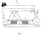
- FIG. 1 shows a schematic side view of a first preferred embodiment of the present invention.
- the device 10 for stabilizing workpieces 20 during a cleaning process comprises a support element 30, a conveying means 40, a plurality of first stabilizing devices 50 made of steel wire, with a cross-sectional area of 2 mm 2 , and two blasting means 60 for frozen carbon dioxide (CO 2 ).
- the support member has no openings for receiving the workpieces 20 and 20 'and is arranged on a conveyor 40, which is a conveyor belt in the embodiment shown here.
- a conveyor 40 which is a conveyor belt in the embodiment shown here.
- the stabilizers 50 are connected at their left and right ends to a regulator 90, which in the embodiment shown here comprises a motor (not shown) and a coil (not shown).
- the regulation devices 90 are connected to a controller 80 via data cables, the controller 80 being a computer.
- blasting means 60 are connected to a control device 80 by means of a signal cable.
- a CCD camera 70, a conveying motor 45 for operating the conveying means 40, and a user interface 85 are also connected to the control device 80 via corresponding signal and data cables.
- the control device 80 and the associated components such as the regulating device 90, the blasting means 60 and the CCD camera 70 are activated.
- the conveyor 40 is activated in a kind of idling by means of two feed motors 45, wherein idle, the conveyor 40 is not yet moved in a first direction of movement R. Only after the control unit 80 has checked the operating status of the device 10 and has determined that all the necessary operating characteristics are correct in the components can the device 10 continue to be put into operation by an authorized user via the user interface 85.
- the support member 30 with the workpieces 20 and 20 'thereon moves by means of the conveyor 40 at a speed of 0.05 m / s in the direction of movement R.
- the CCD camera 70 the device 10 detects a height of 30 cm of the workpieces 20 and 20 'to be cleaned and forwards this information in the form of signal data to the control device 80.
- the control device 80 recognizes that the stabilizers 50 only have a height of 25.3 cm above the support element 30, the control device 80 regulates the height of the first stabilizers 50 30.3 cm above the support element 30 via the regulating device 90, so that the Stabilization devices the workpieces 20 and 20 'subsequently not affected in a movement of the support member 30 in the direction of movement R.
- the stabilizers 50 extend above the surface of the support member 30 at a height of 30.3 cm, that is, the stabilizers 50 are 3 mm above the workpieces 20 and 20 'and do not touch them.
- the two CO 2 -strahlstoff 60 are automatically activated via the control device 80 and emit frozen carbon dioxide (dry ice) by means of their nozzles with a pressure of 5 bar on the workpieces 20 and 20 '.
- the carbon dioxide is passed by means of appropriate lines of carbon dioxide containers to the blasting agent 60.
- the height of the two blasting means 60 is designed to efficiently irradiate even larger workpieces up to a height of 250 cm.
- the beam path of the blasting means 60 is conical and has a lower beam cone area of 200 cm 2 . The distance of the blasting means with respect to the workpieces 20 can be changed and thus also the beam cone surface of the blasting means 60.
- the blasting means 60 have a distance of 100 mm from the surface of the workpieces 20.
- the blasting means are arranged in this embodiment so as to irradiate the largest possible area of the workpieces 20 and 20 '. Further, the centers of the beam cones are spatially offset as much as possible, but overlap each other in a boundary region of the beam cone.
- the first workpiece 20 is illuminated by the first blasting medium 60 in such a way that it is partially raised at a first time and would like to move on the support element 30. A movement on the support member 30 is counteracted, however, because the first stabilizing means 50 do not allow too much lifting of the support member 30 or moving on the support member 30 and the workpiece 20 is pushed back by the stabilizers 50 on the support member 30.
- the workpiece 20 'tilts with its bottom of the support member 30 by an angle ⁇ of 2 °, so that its left height shifts laterally by 3 mm and the stabilizing means 50 touches.
- the workpiece 20 'tilts back into its rest position and completely contacts with its lower surface the support element 30th
- the workpiece 20 has moved on the support member 30 and has rotated on the support member 30 by 40 °.
- the workpiece 20 was not sufficiently cleaned on a surface side.
- the user of the device engages in the process flow by means of the user interface 85 and first stops the device 10.
- the conveyor 40 is in the offset by 180 ° to the direction of movement R movement direction R 'at a speed of 0.05 m / S moves until the desired cleaning effect on the previously insufficiently cleaned surface of the workpiece 20 has been achieved, the degree of cleaning of the workpiece 20 is determined by means of a CCD camera 70 by the user.
- the conveying means 40 again moved in the direction of movement R and the cleaning process continued until the last on the support member 20 located workpiece, in this case, the workpiece 20 'has passed through the beam cone of the blasting agent 60.
- the end of the support element 40 is detected by means of the CCD camera 70, which sends a corresponding signal to the control device 80, which deactivates the conveyor motor 45 of the conveyor 40 and transmits to the user interface 85 a corresponding message about the end of the cleaning process.
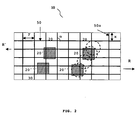
- FIG. 2 illustrates another preferred embodiment of the present invention, wherein a schematic plan view of the first 50 and second 50a stabilizers is shown.
- the first stabilizers 50 extend along the first direction of travel R.
- the second stabilizers 50a extend at an angle ⁇ of 90 ° to the first stabilizers 50 and touch them, but are not connected to them.
- the first stabilizing devices 50 have a distance x of 15 mm from each other and the second stabilizing devices 50a from each other a distance y of 20 mm.
- the support member 30 and four workpieces 20, 20 ', 20' ', 20' '' are shown in plan view, which are located at different locations of the support member 30.
- the support member 30 with the workpieces moves in the direction of movement R, ie from left to right, so comes the workpiece 20, which is right up, first, at a first time in the beam cone, the shown here as a dashed circle, a first blasting agent 60 (not shown). At a later time, the workpiece 20 enters the second beam cone, which lies below the first beam cone and is offset more to the left.
- the device is automatically controlled by the controller 80 (not shown) or the user via the user interface 85 (not shown) can engage and the conveyor motors 45 (not shown) stops.
- the conveyor 40 is moved in the direction of movement R ', which is opposite to the direction of movement R, at a speed of 0.05 m / s.
- the cleaning process is continued again in the direction of movement R and, as previously in Fig. 1 has been described in detail, terminated if the end of the support member 30 is reached.
- FIG. 3 represents a further preferred embodiment of the present invention.
- the first stabilizers 50 which extend in the direction R, have a preformed, workpiece-specific shape that takes into account the shape of a larger workpiece.
- the first stabilizing devices 50 are preformed so rigidly in this embodiment that with the selected geometry, a larger workpiece 20 'under the type "bell curve" of the first stabilizers 50 fits and also in the beam cone of the blasting means 60 a distance of 3 mm to the first stabilizing devices 50 and this does not affect.
- the workpiece 20 'following the first workpiece 20 has a height of 45 cm, and the first stabilizers 50 have a distance of 3 mm from this workpiece 20'.
- the control device 80 determines that the height of the first stabilizers 90 above the support element 30 is only 25.3 cm.
- the CCD camera 70 determines that the first workpiece 20 is followed by another workpiece 20 ', which has a greater height than the first workpiece 20, namely 45 cm.
- this height of the second workpiece 20 ' has already been taken into account beforehand by determining the respective sizes and spacings of the workpieces 20, 20' and 20 ".
- the third height of the third workpiece 20 "of 30 cm is already considered.
- the first stabilizing means 50 are lowered, brought to a height of 30.3 cm above the support element 30 and thereby each have a distance of 3 mm from the individual workpieces 20, 20 'and 20''on.
- first stabilizers 50 By the geometry of the first stabilizers 50, it is possible to obtain the distance of 3 mm of the first stabilizers to the first workpiece 20 and 3 mm to the second, higher workpiece 20 'and 3 mm to the third workpiece 20' ' ,
- the first stabilizers 50 in areas of the beam cones of the blasting means 60 to the workpiece 20 have only a small height and stabilize during the cleaning process for the workpieces 20 and cause no shadowing on the workpieces 20 to be cleaned.
- the height of the first stabilizers 50 is again regulated such that the area located earlier than the first workpiece 20 does not contact the second, higher workpiece 20 '.
- the first stabilizers 50 are thus lifted by the regulating device 90 in such a way that also the region which is first located above the first workpiece 20 now has a distance of 3 mm above the second, higher workpiece 20.
- the device 10 is stopped is moved and the support member 30 in the direction of movement R 'at a speed of 0.05 m / s for 30 seconds and then again in the direction of movement of R.
- FIG. 4 shows a schematic side view of another preferred embodiment of the present invention.
- the illustrated apparatus 10 for stabilizing workpieces 20, 20 'and 20 "during a cleaning process comprises a support element 30, a conveyor 40, a plurality of first steel wire stabilizers 50 to 50n, with a cross-sectional area of 2 mm 2 , and two blasting means 60 for frozen carbon dioxide (CO 2 ).
- the device 10 also includes the already in Fig. 1 featured components of a regulator 90, a sensor 70, and a controller 80.
- Fig. 4 Unlike the in Fig. 3 illustrated device 10 extends in Fig. 4 the direction of movement R of the conveyor 40 out of the plane.
- the first stabilizers 50 to 50n extend in the drawing plane in the embodiment shown here. They run parallel to the direction of movement R.
- the first stabilizers 50 to 50n are connected to regulators 90 to 90n.
- the points to the right of the regulator 90a and to the left of the regulator 90n-1 illustrate that there are a plurality of connections between the stabilizers 50 to 50n and the regulators 90 to 90n.
- the first stabilizing devices 50 to 50n are adjusted by means of the regulating devices 90 to 90n corresponding to the height of the workpieces 20, 20 'and 20 "to be cleaned, whereby they have a distance d from the individual workpieces from the regulator 90, the stabilizer 50x from the regulator 90x and the stabilizer 50n from the regulator 90n are regulated in height.
- Fig. 4 it can be seen that during a cleaning process the first stabilizing devices 50 to 50n are adapted to the corresponding geometry of the workpieces to be cleaned and have a distance d from them.
- the first stabilizing devices 50 to 50n are regulated by means of the regulating devices 90 to 90 n and adjusted so that they do not touch the workpieces to be cleaned during a cleaning process.
- the arrangement of the stabilizing devices 50 to 50n shown here makes it possible to optimally clean also workpieces 20, 20 'and 20' 'which have a different height.
- FIG. 5 a schematic representation of the flow profile of the cleaning jets of CO 2 -strahlstoffs, which are discharged from the blasting means 60, around the stabilizers.
- the workpiece 20 the beam profile of the cleaning jets, the cross section of two stabilizers 50, and the inflow (arrow) of the cleaning jets are shown.
- the viewing direction runs in the first direction of movement (R) of the conveyor 40.
- the airfoil Before and after the cross-sectional profile of the stabilizers 50, the airfoil has a laminar flow pattern, i. the flow lines are nearly parallel to each other. In the area of the laterally greatest approximation of the cleaning jets to the stabilizing devices 50, the flow lines are compressed.
- Fig. 5 It can also be seen that the airfoil of the cleaning jets after having radiated the stabilizers 50 has the same flow profile as before passing the stabilizers 50 when the stabilizers 50 have a sufficiently large distance d from the workpieces to be cleaned. Thus, there is no shadowing on the workpieces and the surface of the workpiece can be cleaned evenly.
- a device and a method are provided, which are designed to stabilize and clean workpieces in a simple and cost-effective manner by means of suitable stabilizers and thereby create a shadow on the Prevent workpieces.
Landscapes
- Engineering & Computer Science (AREA)
- Mechanical Engineering (AREA)
- Cleaning In General (AREA)
- Treatment Of Fiber Materials (AREA)
- Cleaning And De-Greasing Of Metallic Materials By Chemical Methods (AREA)
- Electrical Discharge Machining, Electrochemical Machining, And Combined Machining (AREA)
- Cleaning By Liquid Or Steam (AREA)
- Sanitary Device For Flush Toilet (AREA)
- Water Treatment By Sorption (AREA)
Priority Applications (1)
| Application Number | Priority Date | Filing Date | Title |
|---|---|---|---|
| PL07008581T PL1852191T3 (pl) | 2006-05-02 | 2007-04-26 | Urządzenie i sposób stabilizacji przedmiotów obrabianych podczas operacji oczyszczania |
Applications Claiming Priority (1)
| Application Number | Priority Date | Filing Date | Title |
|---|---|---|---|
| DE102006020203A DE102006020203B3 (de) | 2006-05-02 | 2006-05-02 | Vorrichtung und Verfahren zur Stabilisierung von Werkstücken während eines Reinigungsvorgangs |
Publications (2)
| Publication Number | Publication Date |
|---|---|
| EP1852191A1 EP1852191A1 (de) | 2007-11-07 |
| EP1852191B1 true EP1852191B1 (de) | 2008-07-09 |
Family
ID=38512627
Family Applications (1)
| Application Number | Title | Priority Date | Filing Date |
|---|---|---|---|
| EP07008581A Active EP1852191B1 (de) | 2006-05-02 | 2007-04-26 | Vorrichtung und Verfahren zur Stabilisierung von Werkstücken während eines Reinigungsvorgangs |
Country Status (7)
| Country | Link |
|---|---|
| EP (1) | EP1852191B1 (da) |
| AT (1) | ATE400372T1 (da) |
| DE (2) | DE102006020203B3 (da) |
| DK (1) | DK1852191T3 (da) |
| ES (1) | ES2309975T3 (da) |
| PL (1) | PL1852191T3 (da) |
| PT (1) | PT1852191E (da) |
Families Citing this family (1)
| Publication number | Priority date | Publication date | Assignee | Title |
|---|---|---|---|---|
| IT202200017757A1 (it) * | 2022-08-30 | 2024-03-01 | Scm Group Spa | Centro di lavoro per la lavorazione di pezzi in legno, provvisto di un sistema di rilevamento dello stato di pulizia di componenti del centro di lavoro e metodo di funzionamento relativo. |
Family Cites Families (4)
| Publication number | Priority date | Publication date | Assignee | Title |
|---|---|---|---|---|
| DE3174301D1 (en) * | 1980-06-07 | 1986-05-15 | Wynn Ltd G W | Saw guide apparatus |
| US4741783A (en) * | 1986-12-31 | 1988-05-03 | Masonite Corporation | Apparatus and method for rotary buffing |
| US5580394A (en) * | 1993-07-12 | 1996-12-03 | Airtronic, Inc. | Method for cleaning industrial parts including sequential direct spray and immersion of the part |
| DE19508840B4 (de) * | 1995-03-11 | 2005-06-09 | Räuchle, Hans | Waschvorrichtung für beim Backen von Lebensmitteln verwendete Backunterlagen |
-
2006
- 2006-05-02 DE DE102006020203A patent/DE102006020203B3/de not_active Expired - Fee Related
-
2007
- 2007-04-26 PT PT07008581T patent/PT1852191E/pt unknown
- 2007-04-26 PL PL07008581T patent/PL1852191T3/pl unknown
- 2007-04-26 AT AT07008581T patent/ATE400372T1/de active
- 2007-04-26 DE DE502007000036T patent/DE502007000036D1/de active Active
- 2007-04-26 DK DK07008581T patent/DK1852191T3/da active
- 2007-04-26 EP EP07008581A patent/EP1852191B1/de active Active
- 2007-04-26 ES ES07008581T patent/ES2309975T3/es active Active
Also Published As
| Publication number | Publication date |
|---|---|
| EP1852191A1 (de) | 2007-11-07 |
| DK1852191T3 (da) | 2008-11-03 |
| DE502007000036D1 (de) | 2008-08-21 |
| DE102006020203B3 (de) | 2008-01-10 |
| PL1852191T3 (pl) | 2008-12-31 |
| ATE400372T1 (de) | 2008-07-15 |
| PT1852191E (pt) | 2008-09-30 |
| ES2309975T3 (es) | 2008-12-16 |
Similar Documents
| Publication | Publication Date | Title |
|---|---|---|
| EP3661692B1 (de) | Verfahren zum laserschneiden plattenförmiger werkstücke | |
| EP1513749B1 (de) | Förderung von schüttgutteilen | |
| EP3528996B1 (de) | Verfahren zur vorhersage der kippneigung eines freigeschnittenen werkstückteils und bearbeitungsmaschine zur trennenden bearbeitung eines plattenförmigen werkstücks | |
| EP3268162B1 (de) | Maschine zum trennenden bearbeiten von plattenförmigen werkstücken | |
| WO2015027346A1 (de) | Verfahren zum kontinuierlichen transportieren und stumpfen verschweissen von blechteilen und eine anwendung des verfahrens | |
| EP4225526B1 (de) | Verfahren und maschine zum schneiden und entnehmen von werkstückteilen aus einem plattenförmigen material | |
| DE102011002808A1 (de) | Bandabblasvorrichtung | |
| DE102004034256A1 (de) | Vorrichtung zum Schneiden von Blech | |
| DE102015217015B3 (de) | Verfahren und Vorrichtung zur Herstellung einer Blechplatine mittels Laserschneiden | |
| EP3169613B1 (de) | Vibrationsrinne und vibrationsfördervorrichtung zum transport geschindelter produkte in der lebensmittelproduktion | |
| EP3310524A1 (de) | Verfahren zum hauptzeitparallelen entladen eines freigeschnittenen werkstückteils, zugehörige laserschneidmaschine und computerprogrammprodukt | |
| EP1852191B1 (de) | Vorrichtung und Verfahren zur Stabilisierung von Werkstücken während eines Reinigungsvorgangs | |
| DE102016124384B4 (de) | Verfahren und Vorrichtung zum Fügen von Werkstücken | |
| DE2059113C3 (de) | Verfahren und Vorrichtung zum / Trennen von vorgeritztem Tafelglas in einzelne Scheiben | |
| DE102018133552B4 (de) | Biegemaschine, Bearbeitungslinie und Verfahren zum Biegen | |
| DE102008000892B4 (de) | Zuführsystem für Kleinteile | |
| DE102011051156A1 (de) | Bearbeitungsmaschine sowie deren Bearbeitungsverfahren | |
| WO2023041420A1 (de) | Förderbandsteuerung für eine laserschneidanlage | |
| WO2021228580A1 (de) | Vorrichtung und verfahren zum leiten und führen von fischen | |
| DE19534954A1 (de) | Hochspeicher für Werkstücke und Verfahren zum Betreiben eines Hochspeichers | |
| EP1837084A2 (de) | Vorrichtung zur Spritzbeschichtung von Werkstücken | |
| DE102024124122B3 (de) | Verfahren und Vorrichtung zum Trennen von schüttgutähnlichen glatten Stückgütern und stumpfen Teilen, insbesondere nach einem Bearbeitungsprozess | |
| DE69009031T2 (de) | Positionierungsvorrichtung für die Herstellung von gedruckten Leiterplatten. | |
| WO2013000495A1 (de) | System zum schneiden von folie insbesondere für membran-elektronen-einheiten von brennstoffzellen | |
| DE10037658C2 (de) | Vorrichtung zum Aussortieren von Brettern aus einem Bretterteppich |
Legal Events
| Date | Code | Title | Description |
|---|---|---|---|
| PUAI | Public reference made under article 153(3) epc to a published international application that has entered the european phase |
Free format text: ORIGINAL CODE: 0009012 |
|
| AK | Designated contracting states |
Kind code of ref document: A1 Designated state(s): AT BE BG CH CY CZ DE DK EE ES FI FR GB GR HU IE IS IT LI LT LU LV MC MT NL PL PT RO SE SI SK TR |
|
| AX | Request for extension of the european patent |
Extension state: AL BA HR MK YU |
|
| 17P | Request for examination filed |
Effective date: 20071019 |
|
| GRAP | Despatch of communication of intention to grant a patent |
Free format text: ORIGINAL CODE: EPIDOSNIGR1 |
|
| GRAS | Grant fee paid |
Free format text: ORIGINAL CODE: EPIDOSNIGR3 |
|
| GRAA | (expected) grant |
Free format text: ORIGINAL CODE: 0009210 |
|
| AK | Designated contracting states |
Kind code of ref document: B1 Designated state(s): AT BE BG CH CY CZ DE DK EE ES FI FR GB GR HU IE IS IT LI LT LU LV MC MT NL PL PT RO SE SI SK TR |
|
| REG | Reference to a national code |
Ref country code: GB Ref legal event code: FG4D Free format text: NOT ENGLISH |
|
| AKX | Designation fees paid |
Designated state(s): AT BE BG CH CY CZ DE DK EE ES FI FR GB GR HU IE IS IT LI LT LU LV MC MT NL PL PT RO SE SI SK TR |
|
| REG | Reference to a national code |
Ref country code: CH Ref legal event code: EP |
|
| REF | Corresponds to: |
Ref document number: 502007000036 Country of ref document: DE Date of ref document: 20080821 Kind code of ref document: P |
|
| REG | Reference to a national code |
Ref country code: IE Ref legal event code: FG4D Free format text: LANGUAGE OF EP DOCUMENT: GERMAN |
|
| REG | Reference to a national code |
Ref country code: PT Ref legal event code: SC4A Free format text: AVAILABILITY OF NATIONAL TRANSLATION Effective date: 20080917 |
|
| REG | Reference to a national code |
Ref country code: GR Ref legal event code: EP Ref document number: 20080402532 Country of ref document: GR |
|
| REG | Reference to a national code |
Ref country code: SE Ref legal event code: TRGR |
|
| REG | Reference to a national code |
Ref country code: DK Ref legal event code: T3 |
|
| REG | Reference to a national code |
Ref country code: ES Ref legal event code: FG2A Ref document number: 2309975 Country of ref document: ES Kind code of ref document: T3 |
|
| REG | Reference to a national code |
Ref country code: PL Ref legal event code: T3 |
|
| PG25 | Lapsed in a contracting state [announced via postgrant information from national office to epo] |
Ref country code: LT Free format text: LAPSE BECAUSE OF FAILURE TO SUBMIT A TRANSLATION OF THE DESCRIPTION OR TO PAY THE FEE WITHIN THE PRESCRIBED TIME-LIMIT Effective date: 20080709 Ref country code: IS Free format text: LAPSE BECAUSE OF FAILURE TO SUBMIT A TRANSLATION OF THE DESCRIPTION OR TO PAY THE FEE WITHIN THE PRESCRIBED TIME-LIMIT Effective date: 20081109 |
|
| PG25 | Lapsed in a contracting state [announced via postgrant information from national office to epo] |
Ref country code: FI Free format text: LAPSE BECAUSE OF FAILURE TO SUBMIT A TRANSLATION OF THE DESCRIPTION OR TO PAY THE FEE WITHIN THE PRESCRIBED TIME-LIMIT Effective date: 20080709 Ref country code: SI Free format text: LAPSE BECAUSE OF FAILURE TO SUBMIT A TRANSLATION OF THE DESCRIPTION OR TO PAY THE FEE WITHIN THE PRESCRIBED TIME-LIMIT Effective date: 20080709 Ref country code: BG Free format text: LAPSE BECAUSE OF FAILURE TO SUBMIT A TRANSLATION OF THE DESCRIPTION OR TO PAY THE FEE WITHIN THE PRESCRIBED TIME-LIMIT Effective date: 20081009 Ref country code: LV Free format text: LAPSE BECAUSE OF FAILURE TO SUBMIT A TRANSLATION OF THE DESCRIPTION OR TO PAY THE FEE WITHIN THE PRESCRIBED TIME-LIMIT Effective date: 20080709 |
|
| REG | Reference to a national code |
Ref country code: HU Ref legal event code: AG4A Ref document number: E004159 Country of ref document: HU |
|
| REG | Reference to a national code |
Ref country code: IE Ref legal event code: FD4D |
|
| PG25 | Lapsed in a contracting state [announced via postgrant information from national office to epo] |
Ref country code: IE Free format text: LAPSE BECAUSE OF FAILURE TO SUBMIT A TRANSLATION OF THE DESCRIPTION OR TO PAY THE FEE WITHIN THE PRESCRIBED TIME-LIMIT Effective date: 20080709 Ref country code: EE Free format text: LAPSE BECAUSE OF FAILURE TO SUBMIT A TRANSLATION OF THE DESCRIPTION OR TO PAY THE FEE WITHIN THE PRESCRIBED TIME-LIMIT Effective date: 20080709 |
|
| PLBE | No opposition filed within time limit |
Free format text: ORIGINAL CODE: 0009261 |
|
| STAA | Information on the status of an ep patent application or granted ep patent |
Free format text: STATUS: NO OPPOSITION FILED WITHIN TIME LIMIT |
|
| PG25 | Lapsed in a contracting state [announced via postgrant information from national office to epo] |
Ref country code: RO Free format text: LAPSE BECAUSE OF FAILURE TO SUBMIT A TRANSLATION OF THE DESCRIPTION OR TO PAY THE FEE WITHIN THE PRESCRIBED TIME-LIMIT Effective date: 20080709 Ref country code: SK Free format text: LAPSE BECAUSE OF FAILURE TO SUBMIT A TRANSLATION OF THE DESCRIPTION OR TO PAY THE FEE WITHIN THE PRESCRIBED TIME-LIMIT Effective date: 20080709 |
|
| 26N | No opposition filed |
Effective date: 20090414 |
|
| PGFP | Annual fee paid to national office [announced via postgrant information from national office to epo] |
Ref country code: DK Payment date: 20090423 Year of fee payment: 3 Ref country code: ES Payment date: 20090424 Year of fee payment: 3 |
|
| PGFP | Annual fee paid to national office [announced via postgrant information from national office to epo] |
Ref country code: AT Payment date: 20090423 Year of fee payment: 3 Ref country code: CZ Payment date: 20090416 Year of fee payment: 3 Ref country code: FR Payment date: 20090420 Year of fee payment: 3 Ref country code: PL Payment date: 20090416 Year of fee payment: 3 Ref country code: SE Payment date: 20090427 Year of fee payment: 3 |
|
| PGFP | Annual fee paid to national office [announced via postgrant information from national office to epo] |
Ref country code: BE Payment date: 20090429 Year of fee payment: 3 |
|
| PGFP | Annual fee paid to national office [announced via postgrant information from national office to epo] |
Ref country code: HU Payment date: 20090427 Year of fee payment: 3 Ref country code: PT Payment date: 20090828 Year of fee payment: 3 |
|
| PG25 | Lapsed in a contracting state [announced via postgrant information from national office to epo] |
Ref country code: MC Free format text: LAPSE BECAUSE OF NON-PAYMENT OF DUE FEES Effective date: 20090430 |
|
| BERE | Be: lapsed |
Owner name: VENJAKOB MASCHINENBAU G.M.B.H. & CO. KG Effective date: 20100430 |
|
| REG | Reference to a national code |
Ref country code: PT Ref legal event code: MM4A Free format text: LAPSE DUE TO NON-PAYMENT OF FEES Effective date: 20101026 |
|
| REG | Reference to a national code |
Ref country code: NL Ref legal event code: V1 Effective date: 20101101 |
|
| EUG | Se: european patent has lapsed | ||
| REG | Reference to a national code |
Ref country code: DK Ref legal event code: EBP |
|
| REG | Reference to a national code |
Ref country code: FR Ref legal event code: ST Effective date: 20101230 |
|
| PG25 | Lapsed in a contracting state [announced via postgrant information from national office to epo] |
Ref country code: NL Free format text: LAPSE BECAUSE OF NON-PAYMENT OF DUE FEES Effective date: 20101101 |
|
| PG25 | Lapsed in a contracting state [announced via postgrant information from national office to epo] |
Ref country code: PT Free format text: LAPSE BECAUSE OF NON-PAYMENT OF DUE FEES Effective date: 20101026 Ref country code: HU Free format text: LAPSE BECAUSE OF NON-PAYMENT OF DUE FEES Effective date: 20100427 Ref country code: CZ Free format text: LAPSE BECAUSE OF NON-PAYMENT OF DUE FEES Effective date: 20100426 |
|
| PG25 | Lapsed in a contracting state [announced via postgrant information from national office to epo] |
Ref country code: IT Free format text: LAPSE BECAUSE OF NON-PAYMENT OF DUE FEES Effective date: 20100426 Ref country code: GR Free format text: LAPSE BECAUSE OF NON-PAYMENT OF DUE FEES Effective date: 20101103 Ref country code: BE Free format text: LAPSE BECAUSE OF NON-PAYMENT OF DUE FEES Effective date: 20100430 |
|
| PG25 | Lapsed in a contracting state [announced via postgrant information from national office to epo] |
Ref country code: LU Free format text: LAPSE BECAUSE OF NON-PAYMENT OF DUE FEES Effective date: 20090426 Ref country code: DK Free format text: LAPSE BECAUSE OF NON-PAYMENT OF DUE FEES Effective date: 20100503 |
|
| REG | Reference to a national code |
Ref country code: ES Ref legal event code: FD2A Effective date: 20110708 |
|
| PG25 | Lapsed in a contracting state [announced via postgrant information from national office to epo] |
Ref country code: ES Free format text: LAPSE BECAUSE OF NON-PAYMENT OF DUE FEES Effective date: 20110628 |
|
| PGFP | Annual fee paid to national office [announced via postgrant information from national office to epo] |
Ref country code: DE Payment date: 20110421 Year of fee payment: 5 |
|
| PG25 | Lapsed in a contracting state [announced via postgrant information from national office to epo] |
Ref country code: CY Free format text: LAPSE BECAUSE OF FAILURE TO SUBMIT A TRANSLATION OF THE DESCRIPTION OR TO PAY THE FEE WITHIN THE PRESCRIBED TIME-LIMIT Effective date: 20080709 Ref country code: ES Free format text: LAPSE BECAUSE OF NON-PAYMENT OF DUE FEES Effective date: 20100427 |
|
| PGFP | Annual fee paid to national office [announced via postgrant information from national office to epo] |
Ref country code: IT Payment date: 20110427 Year of fee payment: 5 |
|
| PGFP | Annual fee paid to national office [announced via postgrant information from national office to epo] |
Ref country code: TR Payment date: 20090420 Year of fee payment: 3 |
|
| REG | Reference to a national code |
Ref country code: CH Ref legal event code: PL |
|
| GBPC | Gb: european patent ceased through non-payment of renewal fee |
Effective date: 20110426 |
|
| PG25 | Lapsed in a contracting state [announced via postgrant information from national office to epo] |
Ref country code: LI Free format text: LAPSE BECAUSE OF NON-PAYMENT OF DUE FEES Effective date: 20110430 Ref country code: CH Free format text: LAPSE BECAUSE OF NON-PAYMENT OF DUE FEES Effective date: 20110430 |
|
| PG25 | Lapsed in a contracting state [announced via postgrant information from national office to epo] |
Ref country code: PL Free format text: LAPSE BECAUSE OF NON-PAYMENT OF DUE FEES Effective date: 20100426 Ref country code: GB Free format text: LAPSE BECAUSE OF NON-PAYMENT OF DUE FEES Effective date: 20110426 |
|
| REG | Reference to a national code |
Ref country code: PL Ref legal event code: LAPE |
|
| PG25 | Lapsed in a contracting state [announced via postgrant information from national office to epo] |
Ref country code: FR Free format text: LAPSE BECAUSE OF NON-PAYMENT OF DUE FEES Effective date: 20100430 |
|
| PG25 | Lapsed in a contracting state [announced via postgrant information from national office to epo] |
Ref country code: SE Free format text: LAPSE BECAUSE OF NON-PAYMENT OF DUE FEES Effective date: 20100427 |
|
| REG | Reference to a national code |
Ref country code: AT Ref legal event code: MM01 Ref document number: 400372 Country of ref document: AT Kind code of ref document: T Effective date: 20120426 |
|
| PG25 | Lapsed in a contracting state [announced via postgrant information from national office to epo] |
Ref country code: TR Free format text: LAPSE BECAUSE OF NON-PAYMENT OF DUE FEES Effective date: 20100426 Ref country code: AT Free format text: LAPSE BECAUSE OF NON-PAYMENT OF DUE FEES Effective date: 20120426 |
|
| REG | Reference to a national code |
Ref country code: DE Ref legal event code: R119 Ref document number: 502007000036 Country of ref document: DE Effective date: 20121101 |
|
| PG25 | Lapsed in a contracting state [announced via postgrant information from national office to epo] |
Ref country code: IT Free format text: LAPSE BECAUSE OF NON-PAYMENT OF DUE FEES Effective date: 20120426 |
|
| PG25 | Lapsed in a contracting state [announced via postgrant information from national office to epo] |
Ref country code: DE Free format text: LAPSE BECAUSE OF NON-PAYMENT OF DUE FEES Effective date: 20121101 |