EP1852377A2 - Dispositif de jonction d'une pile secondaire et d'une pile principale dans un margeur d'une machine d'impression de feuilles - Google Patents
Dispositif de jonction d'une pile secondaire et d'une pile principale dans un margeur d'une machine d'impression de feuilles Download PDFInfo
- Publication number
- EP1852377A2 EP1852377A2 EP07008047A EP07008047A EP1852377A2 EP 1852377 A2 EP1852377 A2 EP 1852377A2 EP 07008047 A EP07008047 A EP 07008047A EP 07008047 A EP07008047 A EP 07008047A EP 1852377 A2 EP1852377 A2 EP 1852377A2
- Authority
- EP
- European Patent Office
- Prior art keywords
- stack
- auxiliary stack
- auxiliary
- support
- pallet
- Prior art date
- Legal status (The legal status is an assumption and is not a legal conclusion. Google has not performed a legal analysis and makes no representation as to the accuracy of the status listed.)
- Granted
Links
- 238000000151 deposition Methods 0.000 claims 1
- 230000037431 insertion Effects 0.000 description 6
- 238000003780 insertion Methods 0.000 description 6
- 230000001419 dependent effect Effects 0.000 description 1
- 238000005096 rolling process Methods 0.000 description 1
- 238000007665 sagging Methods 0.000 description 1
- 239000002699 waste material Substances 0.000 description 1
Images


Classifications
-
- B—PERFORMING OPERATIONS; TRANSPORTING
- B65—CONVEYING; PACKING; STORING; HANDLING THIN OR FILAMENTARY MATERIAL
- B65H—HANDLING THIN OR FILAMENTARY MATERIAL, e.g. SHEETS, WEBS, CABLES
- B65H1/00—Supports or magazines for piles from which articles are to be separated
- B65H1/30—Supports or magazines for piles from which articles are to be separated with means for replenishing the pile during continuous separation of articles therefrom
-
- B—PERFORMING OPERATIONS; TRANSPORTING
- B65—CONVEYING; PACKING; STORING; HANDLING THIN OR FILAMENTARY MATERIAL
- B65H—HANDLING THIN OR FILAMENTARY MATERIAL, e.g. SHEETS, WEBS, CABLES
- B65H2405/00—Parts for holding the handled material
- B65H2405/30—Other features of supports for sheets
- B65H2405/32—Supports for sheets partially insertable - extractable, e.g. upon sliding movement, drawer
- B65H2405/321—Shutter type element, i.e. involving multiple interlinked support elements
-
- B—PERFORMING OPERATIONS; TRANSPORTING
- B65—CONVEYING; PACKING; STORING; HANDLING THIN OR FILAMENTARY MATERIAL
- B65H—HANDLING THIN OR FILAMENTARY MATERIAL, e.g. SHEETS, WEBS, CABLES
- B65H2801/00—Application field
- B65H2801/03—Image reproduction devices
- B65H2801/21—Industrial-size printers, e.g. rotary printing press
Definitions
- the invention relates to a device for uniting an auxiliary stack and a main stack in a feeder of a sheet-fed press according to the preamble of claim 1.
- the device disclosed therein comprises a main stack lifting device designed as a lifting mechanism for lifting a main stack stacked on a pallet. Furthermore, the device disclosed there comprises an auxiliary stack support device for carrying an auxiliary stack, wherein the auxiliary stack support device and thus the auxiliary stack positioned on the auxiliary stack support device can be raised by means of an auxiliary stack lifting device designed as an auxiliary stack lift.
- a main stack via the Hauptstapelhub For uniting an auxiliary stack and a main stack, a main stack via the Hauptstapelhub founded with an upper side thereof in the direction of the attacking on an underside of the auxiliary stack auxiliary stack support means, wherein then the auxiliary stack support means storing the auxiliary stack on the top of the main stack from the area of the underside of the auxiliary stack is removable.
- the auxiliary stack support device which is designed as a stack rake, pulled in the horizontal direction translationally from the bottom of the auxiliary stack, which inevitably follows that projects in the pulled-out state of the stack rake or the auxiliary stack support laterally relative to the investor of the sheet-fed press.
- Another disadvantage of the prior art apparatus for uniting an auxiliary stack with a main stack is the fact that the stack rake is pulled along both the lowermost signature of the auxiliary stack and the topmost signature of the main stack, thereby causing undesirable on those signatures Can form markings.
- the present invention is based on the problem of providing a novel device for uniting an auxiliary stack and a main stack in an investor of a sheet-fed press.
- a device according to claim 1 the auxiliary stack support device has guide elements, in which support elements are displaceably guided, wherein the support elements are formed as rollers and are connected via chain elements such that when combining the auxiliary stack and the main stack connected via the chain elements support elements on the one hand in the horizontal direction from the area of the bottom the auxiliary stack removable and then laterally next to the auxiliary stack or main stack can be wound up or derived in the vertical direction.
- the present invention proposes a device for uniting an auxiliary stack and a main stack in a feeder of a sheet-fed printing press, which does not increase the area required in the area of an investor base of the sheet-fed press.
- a further advantage of the device according to the invention is that the support elements of the auxiliary stack support device designed as rollers, when unrolled on the lowermost sheet of the auxiliary stack and optionally on the uppermost sheet of the main stack in contrast to the known from the prior art stack rake, which pulled over the sheets that will not damage the printed sheets.
- the support elements of the auxiliary stack support means are connected via the chain elements to form at least one stickleitermén support element chain, wherein the or each stickleitermé support element chain from one side between a pallet and a bottom of an arranged on the pallet auxiliary stack is inserted, and wherein the or each stickleiterartigen support element chain at a front end, with which it is first inserted between the pallet and the underside of the arranged on the pallet auxiliary stack, a wedge element is associated.
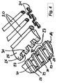
- 1 to 4 show a first embodiment of a device 10 according to the invention for uniting an auxiliary stack 11 and a main stack 12 in a feeder 13 of a sheet-fed press.
- the main stack 12 is positioned on a pallet 14, wherein the pallet 14 can be lifted together with the main stack positioned thereon by means of a Hauptstapelhubvorraum not shown.
- the device 10 has an auxiliary stack support device 15 and an auxiliary stack lifting device 16.
- the auxiliary stack 11 is positioned on the auxiliary stack support device 15, the auxiliary stack support device 15 together with the auxiliary stack 11 positioned on the same via the auxiliary stack lifting device 16 can be raised.
- the Hilfsstapelhub observed 16 is formed by chain-like lifting elements 17 which engage a support frame 18 of the auxiliary stack support means 15.
- the auxiliary stack support device 15 comprises guide elements 19 for support elements 20 of the auxiliary stack support device 15, wherein the guide elements 19 are either attached to opposite spars of the support frame 18 or are formed directly from opposite spars of the support frame 18.
- the guide elements 19 are designed as chain guide rails.
- the support elements 20 are designed as rollers, which are connected to each other via chain elements 21 (see FIGS. 2 to 4).
- support members 20 are connected to each other via the chain elements 21 into a single strickleiterartigen support element chain, according to FIGS. 2 and 3 from one side in the direction of arrow 22 for lifting an auxiliary stack 11 of a Pallet 14 between the bottom of the auxiliary stack 11 and the pallet 14 is inserted.
- the auxiliary stack 11 is raised, specifically by the thickness or height of the ladder-type carrier element chain.
- the pallet 14 can be lowered, in which case the auxiliary stack 11 is completely supported by the auxiliary stack support device 15 of FIG.
- a new main stack 12 can then be introduced in the area of the feeder 13, wherein subsequently the auxiliary stack 11 can be deposited on the upper side of the main stack 12 in order to combine the auxiliary stack 11 with the main stack 12.
- the main stack 12 is movable over the unillustrated Hauptstapelhub observed with an upper side in the direction of the auxiliary stack support means 15, the auxiliary stack 11 at a Bottom of the same recorded.
- the upper side of the main stack 12 is preferably brought to bear against the auxiliary stack support device 15.
- the guided in the guide elements 18, designed as rollers support members 20 are then opposite to the visualized in Fig. 2 and 3 by the arrow 22 direction in the horizontal direction from the area of the underside of the auxiliary stack 11 removable, the rollers 20 on the one hand on the Roll down the bottom sheet of the auxiliary stack 11 and on the other hand on the top sheet of the main stack 12.
- the support elements 20 connected via the chain elements 21 to form a strick-ladder-like support element chain are, as soon as they have been removed from the area of the underside of the auxiliary stack 11, derived in the vertical direction in the exemplary embodiment of FIG. 2, namely in a vertically downwardly extending section 23 of the auxiliary stack support device 15, wherein this section 23 extends in the embodiment of FIG. 1 at a feeder table 24 opposite side of the investor laterally adjacent to the main stack 12.
- the strickleiterartigen support element chain from the via the chain elements 21 knit-like connected support elements 20 at a front end, with which the same is first inserted between the pallet 14 and an auxiliary stack 11, a wedge element 25 assigned.
- the wedge member 25 allows for easy insertion of the strickder-like support element chain between the underside of the auxiliary stack 11 and the pallet 14, without damaging the lower signature of the auxiliary stack 11.
- the wedge element 25 is formed comb-shaped as shown in FIG. 4 and has juxtaposed webs 26, between which grooves 27 are formed.
- the webs 26 and grooves 27 of the wedge member 25 cooperate with webs 28 and grooves 29 of the pallet 14 such that upon insertion (see Figs. 2 and 3) of the wedge member 25 between the underside of the auxiliary stack 14 and the pallet 14, the webs 26 of the Wedge element 25 engage in the grooves 29 of the pallet 14, whereas the webs 28 of the pallet 14 engage in the grooves 27 of the wedge element 25.
- rollers 20 supporting elements of the strickleitertechnikn support element chain roll during insertion thereof between the bottom of the auxiliary stack 11 and the pallet 14 on the webs 28 of the pallet 14 from.
- bores 31 are integrated in the webs 26 of the wedge element 25, through which openings air can be directed between a lower side of an auxiliary stack 11 and a pallet to facilitate the insertion of the wedge element 25.
- an air cushion can be constructed, which allows the insertion of the wedge member 25 with the lowest forces.
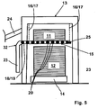
- FIG. 5 A second exemplary embodiment of a device 32 according to the invention for uniting an auxiliary stack with a main stack in the area of an investor of a sheet-fed printing press is shown in FIG. 5, wherein the same reference numerals are used to avoid unnecessary repetitions for the embodiment of FIG. 5 as for the embodiment of FIG to 4.
- the only difference between the embodiment of Fig. 5 and the embodiment of Fig. 1 is the fact that the downwardly directed portion 23 of the auxiliary stack support means 15, in the region of the support members 20 after removing the same from the Subside of the auxiliary stack 11 are derived vertically, on the investor table 24 adjacent side of the investor 13 is positioned laterally adjacent to the main stack 12, thus extending below the feeder table 24.
- FIGS. 6 to 8 A third exemplary embodiment of a device 33 according to the invention for uniting an auxiliary stack with a main stack in the area of an investor of a sheet-fed printing press is shown in FIGS. 6 to 8, wherein the same reference numerals are used for the embodiment of FIGS. 6 to 8 to avoid unnecessary repetitions for the same components.
- FIGS. 6 to 8 differs from the exemplary embodiments of FIGS. 1 to 4 or 5 in that in the embodiment of FIGS. 6 to 8, the support elements 20 of the auxiliary stack support device 15 designed as rollers pass over the chain elements 22 to form two stretcher-type support element chains are connected, namely such that in each case one of these strickleiterartigen support element chains from opposite sides of between a pallet and a bottom of an auxiliary stack 11 is inserted.
- each of the two ladder-type support element chains is then assigned a wedge element 25 in each case.
- the wedge elements 25 are in the embodiment of FIGS. 6 to 8 hinged, so as to prevent a sagging or downward buckling of the sheet of the auxiliary stack 11 in the region of the wedge elements 25.
- Each of the two strickleiterierin support element chains is in the embodiment of Figs. 6 to 8 in a vertically downwardly directed portion 23 of the auxiliary stack support means 15 receivable to save the same space when combining the auxiliary stack 11 with the main stack 12 from the bottom of the auxiliary stack 11.
- FIG. 9 A further exemplary embodiment of a device 34 according to the invention for uniting an auxiliary stack with a main stack in the area of an investor of a sheet-fed printing press is shown in FIG. 9, wherein the embodiment of FIG. 9 substantially corresponds to the embodiment of FIGS. 1 to 4, so that here too identical components same reference numerals are used.
- the embodiment of FIG. 9 differs from the embodiment of FIG. 1 only in that the region 23 of the auxiliary stack support device 15, in which after horizontal removal of the support members 20 from the Area of the underside of the auxiliary stack 11 are derived the same vertically, directed upwards and not directed downwards.
- This has the advantage that the section 23 does not limit the accessibility of the feeder 13 in the area below the auxiliary stack support device 15, so that a main stack 12 can be moved into the area of the feeder 13 from all sides.
- the support elements 20 are respectively moved in or opposite to a conveying direction of the sheet by the sheet-fed press. In contrast to this, it is also possible to move the support elements 20 transversely to the transport direction of the printed sheets, for which purpose the entire device according to the invention has to be mounted on the feeder 13 only offset by 90 °. In this case, then the grooves or webs of the pallet 14 must be offset by 90 ° to the embodiments of FIGS. 1 to 9.
- Each strickleitermén support element chain of the above embodiments is preferably associated with a separate drive for retracting or extending the support elements.
- a separate drive for retracting or extending the support elements.
- both strickleitermé support element chains are present, both are also assigned a common drive.
Landscapes
- Engineering & Computer Science (AREA)
- Mechanical Engineering (AREA)
- Pile Receivers (AREA)
- Sheets, Magazines, And Separation Thereof (AREA)
Applications Claiming Priority (1)
| Application Number | Priority Date | Filing Date | Title |
|---|---|---|---|
| DE102006021214A DE102006021214A1 (de) | 2006-05-06 | 2006-05-06 | Vorrichtung zum Vereinigen eines Hilfsstapels und eines Hauptstapels in einem Anleger einer Bogendruckmaschine |
Publications (3)
| Publication Number | Publication Date |
|---|---|
| EP1852377A2 true EP1852377A2 (fr) | 2007-11-07 |
| EP1852377A3 EP1852377A3 (fr) | 2008-06-25 |
| EP1852377B1 EP1852377B1 (fr) | 2010-10-20 |
Family
ID=38294277
Family Applications (1)
| Application Number | Title | Priority Date | Filing Date |
|---|---|---|---|
| EP07008047A Not-in-force EP1852377B1 (fr) | 2006-05-06 | 2007-04-20 | Dispositif de jonction d'une pile secondaire et d'une pile principale dans un margeur d'une machine d'impression de feuilles |
Country Status (4)
| Country | Link |
|---|---|
| EP (1) | EP1852377B1 (fr) |
| JP (1) | JP2007297214A (fr) |
| AT (1) | ATE485231T1 (fr) |
| DE (2) | DE102006021214A1 (fr) |
Families Citing this family (3)
| Publication number | Priority date | Publication date | Assignee | Title |
|---|---|---|---|---|
| DE102015203412B4 (de) | 2014-03-14 | 2026-03-26 | Heidelberger Druckmaschinen Ag | Stapelanhebevorrichtung |
| DE102018201917B3 (de) | 2018-02-07 | 2019-07-11 | Koenig & Bauer Ag | Bogendruckmaschine mit zumindest einer Substratzufuhreinrichtung |
| EP4731551A1 (fr) * | 2023-06-23 | 2026-04-29 | Sidel Participations | Tête de palettisation pour contenant, à came mobile verticalement |
Citations (3)
| Publication number | Priority date | Publication date | Assignee | Title |
|---|---|---|---|---|
| FR1518016A (fr) | 1967-02-10 | 1968-03-22 | Marinoni | Dispositif d'évacuation, en continu, des piles de feuilles sortant d'une machine à imprimer |
| DE4211353A1 (de) | 1992-04-04 | 1993-10-14 | Heidelberger Druckmasch Ag | Hilfsstapelträger für eine Bogenstapelhubvorrichtung |
| US20040188926A1 (en) | 2003-03-28 | 2004-09-30 | Kenyu Tamura | Sheet delivery device of a sheet-fed press |
Family Cites Families (7)
| Publication number | Priority date | Publication date | Assignee | Title |
|---|---|---|---|---|
| DE1018432B (de) * | 1954-11-20 | 1957-10-31 | Maschf Augsburg Nuernberg Ag | Zwischenstapelvorrichtung fuer bogenverarbeitende Maschinen, insbesondere Druckmaschinen, auf der sich die Bogen waehrend des Auswechselns des Ablegetisches ablegen |
| DE1145637B (de) * | 1961-08-11 | 1963-03-21 | Huck Entwicklung G M B H | Hilfsstapelvorrichtung |
| DD93351A1 (de) * | 1971-12-28 | 1972-10-20 | Fritz Bensch | Hilfsstapeleinrichtung |
| DE4421487C1 (de) * | 1994-05-30 | 1995-05-24 | Roland Man Druckmasch | Verfahren und Vorrichtung zur Vereinigung eines Hauptstapels und eines Hilfsstapels in einem Bogenanleger |
| DE4424287C2 (de) * | 1994-07-09 | 2001-05-31 | Koenig & Bauer Ag | Hilfsstapeleinrichtung |
| DE29610103U1 (de) * | 1996-06-08 | 1996-08-29 | Kba-Planeta Ag, 01445 Radebeul | Antrieb für einen Hilfsstapeltisch |
| DE10233786A1 (de) * | 2002-07-25 | 2004-02-05 | Heidelberger Druckmaschinen Ag | Flächige Bedruckstoffe verarbeitende Maschine mit einem Hilfsstapelträger |
-
2006
- 2006-05-06 DE DE102006021214A patent/DE102006021214A1/de not_active Withdrawn
-
2007
- 2007-04-20 DE DE502007005388T patent/DE502007005388D1/de active Active
- 2007-04-20 EP EP07008047A patent/EP1852377B1/fr not_active Not-in-force
- 2007-04-20 AT AT07008047T patent/ATE485231T1/de active
- 2007-05-02 JP JP2007121915A patent/JP2007297214A/ja active Pending
Patent Citations (3)
| Publication number | Priority date | Publication date | Assignee | Title |
|---|---|---|---|---|
| FR1518016A (fr) | 1967-02-10 | 1968-03-22 | Marinoni | Dispositif d'évacuation, en continu, des piles de feuilles sortant d'une machine à imprimer |
| DE4211353A1 (de) | 1992-04-04 | 1993-10-14 | Heidelberger Druckmasch Ag | Hilfsstapelträger für eine Bogenstapelhubvorrichtung |
| US20040188926A1 (en) | 2003-03-28 | 2004-09-30 | Kenyu Tamura | Sheet delivery device of a sheet-fed press |
Also Published As
| Publication number | Publication date |
|---|---|
| JP2007297214A (ja) | 2007-11-15 |
| ATE485231T1 (de) | 2010-11-15 |
| DE502007005388D1 (de) | 2010-12-02 |
| EP1852377A3 (fr) | 2008-06-25 |
| DE102006021214A1 (de) | 2007-11-08 |
| EP1852377B1 (fr) | 2010-10-20 |
Similar Documents
| Publication | Publication Date | Title |
|---|---|---|
| EP1990190B1 (fr) | Presse rotative à bandes | |
| EP1883538B1 (fr) | Dispositif de maintien pour imprimante a jet d'encre | |
| DE4228616C1 (de) | Bogenanleger an Druckmaschinen | |
| EP1852377B1 (fr) | Dispositif de jonction d'une pile secondaire et d'une pile principale dans un margeur d'une machine d'impression de feuilles | |
| DE19926822A1 (de) | Plattenwechselvorrichtung | |
| DE19910242A1 (de) | Vorrichtung zur Bildung von Stapeln | |
| DE4215791A1 (de) | Stapeltisch mit einer Einrichtung zum Erneuern oder Abnehmen eines Stapels während des fortlaufenden Betriebes einer bogenverarbeitenden Maschine | |
| DE4431488A1 (de) | Bogenführung im Anleger einer Bogendruckmaschine | |
| EP0531786B1 (fr) | Margeur à feuille avec un Non-Stop-arrangement | |
| DE3923475A1 (de) | Bogenausleger fuer druckmaschinen | |
| DE19520772C1 (de) | Non-Stop-Bogenanleger für Druckmaschinen mit ein- und ausfahrbaren Gabelstäben | |
| DE19927921B4 (de) | Hürdenbrett für Bogendruckmaschinen | |
| EP3919223A1 (fr) | Dispositif de transfert permettant de transférer des pièces en forme de plaque et agencement mécanique destiné à l'usinage de pièces en forme de plaque | |
| DE102008032684A1 (de) | Blechtafel-Saugvorrichtung sowie Vorrichtung zum Transport von Blechtafeln in eine Blechdruckmaschine oder Blechlackiermaschine | |
| DE4412661C2 (de) | Vorrichtung zur Aufnahme von Bogenstapeln an einer Bogendruckmaschine | |
| DE19953023B4 (de) | Non-Stop-Einrichtung | |
| DE102020125357B4 (de) | Anleger und Verfahren zum Betrieb eines Anlegers einer bogenverarbeitenden Maschine | |
| EP1155995B1 (fr) | Table de réception | |
| DE102010043738A1 (de) | Bogenführungseinrichtung für einen Bogenanleger | |
| DE19819596C2 (de) | Bogenrückhalter für einen Non-Stop-Stapelwechsler | |
| DE102006021213A1 (de) | Vorrichtung zum Vereinigen eines Hilfsstapels und eines Hauptstapels in einem Anleger einer Bogendruckmaschine | |
| DE202008018495U1 (de) | Blechtafel-Saugvorrichtung und Vorrichtung zum Transport von Blechtafeln in eine Blechdruckmaschine oder Blechlackiermaschine sowie Blechtafel-Transportsystem | |
| EP1155999B1 (fr) | Dispositif pour le changement automatique de piles | |
| DE102009022249B4 (de) | Übergabevorrichtung zur Übergabe eines durch mehrere Blattlagen gebildeten Stapels | |
| DE202008018496U1 (de) | Transportsystem sowie Vorrichtung zum Transport von Blechtafeln in eine Blechdruckmaschine oder Blechlackiermaschine |
Legal Events
| Date | Code | Title | Description |
|---|---|---|---|
| PUAI | Public reference made under article 153(3) epc to a published international application that has entered the european phase |
Free format text: ORIGINAL CODE: 0009012 |
|
| AK | Designated contracting states |
Kind code of ref document: A2 Designated state(s): AT BE BG CH CY CZ DE DK EE ES FI FR GB GR HU IE IS IT LI LT LU LV MC MT NL PL PT RO SE SI SK TR |
|
| AX | Request for extension of the european patent |
Extension state: AL BA HR MK YU |
|
| PUAL | Search report despatched |
Free format text: ORIGINAL CODE: 0009013 |
|
| AK | Designated contracting states |
Kind code of ref document: A3 Designated state(s): AT BE BG CH CY CZ DE DK EE ES FI FR GB GR HU IE IS IT LI LT LU LV MC MT NL PL PT RO SE SI SK TR |
|
| AX | Request for extension of the european patent |
Extension state: AL BA HR MK RS |
|
| RAP1 | Party data changed (applicant data changed or rights of an application transferred) |
Owner name: MANROLAND AG |
|
| 17P | Request for examination filed |
Effective date: 20081229 |
|
| AKX | Designation fees paid |
Designated state(s): AT BE BG CH CY CZ DE DK EE ES FI FR GB GR HU IE IS IT LI LT LU LV MC MT NL PL PT RO SE SI SK TR |
|
| 17Q | First examination report despatched |
Effective date: 20090213 |
|
| GRAP | Despatch of communication of intention to grant a patent |
Free format text: ORIGINAL CODE: EPIDOSNIGR1 |
|
| GRAS | Grant fee paid |
Free format text: ORIGINAL CODE: EPIDOSNIGR3 |
|
| GRAA | (expected) grant |
Free format text: ORIGINAL CODE: 0009210 |
|
| AK | Designated contracting states |
Kind code of ref document: B1 Designated state(s): AT BE BG CH CY CZ DE DK EE ES FI FR GB GR HU IE IS IT LI LT LU LV MC MT NL PL PT RO SE SI SK TR |
|
| REG | Reference to a national code |
Ref country code: GB Ref legal event code: FG4D Free format text: NOT ENGLISH |
|
| REG | Reference to a national code |
Ref country code: CH Ref legal event code: EP |
|
| REG | Reference to a national code |
Ref country code: IE Ref legal event code: FG4D Free format text: LANGUAGE OF EP DOCUMENT: GERMAN |
|
| REF | Corresponds to: |
Ref document number: 502007005388 Country of ref document: DE Date of ref document: 20101202 Kind code of ref document: P |
|
| REG | Reference to a national code |
Ref country code: NL Ref legal event code: VDEP Effective date: 20101020 |
|
| LTIE | Lt: invalidation of european patent or patent extension |
Effective date: 20101020 |
|
| PG25 | Lapsed in a contracting state [announced via postgrant information from national office to epo] |
Ref country code: LT Free format text: LAPSE BECAUSE OF FAILURE TO SUBMIT A TRANSLATION OF THE DESCRIPTION OR TO PAY THE FEE WITHIN THE PRESCRIBED TIME-LIMIT Effective date: 20101020 |
|
| REG | Reference to a national code |
Ref country code: IE Ref legal event code: FD4D |
|
| PG25 | Lapsed in a contracting state [announced via postgrant information from national office to epo] |
Ref country code: BG Free format text: LAPSE BECAUSE OF FAILURE TO SUBMIT A TRANSLATION OF THE DESCRIPTION OR TO PAY THE FEE WITHIN THE PRESCRIBED TIME-LIMIT Effective date: 20110120 Ref country code: FI Free format text: LAPSE BECAUSE OF FAILURE TO SUBMIT A TRANSLATION OF THE DESCRIPTION OR TO PAY THE FEE WITHIN THE PRESCRIBED TIME-LIMIT Effective date: 20101020 Ref country code: SE Free format text: LAPSE BECAUSE OF FAILURE TO SUBMIT A TRANSLATION OF THE DESCRIPTION OR TO PAY THE FEE WITHIN THE PRESCRIBED TIME-LIMIT Effective date: 20101020 Ref country code: NL Free format text: LAPSE BECAUSE OF FAILURE TO SUBMIT A TRANSLATION OF THE DESCRIPTION OR TO PAY THE FEE WITHIN THE PRESCRIBED TIME-LIMIT Effective date: 20101020 Ref country code: SI Free format text: LAPSE BECAUSE OF FAILURE TO SUBMIT A TRANSLATION OF THE DESCRIPTION OR TO PAY THE FEE WITHIN THE PRESCRIBED TIME-LIMIT Effective date: 20101020 Ref country code: PT Free format text: LAPSE BECAUSE OF FAILURE TO SUBMIT A TRANSLATION OF THE DESCRIPTION OR TO PAY THE FEE WITHIN THE PRESCRIBED TIME-LIMIT Effective date: 20110221 Ref country code: IS Free format text: LAPSE BECAUSE OF FAILURE TO SUBMIT A TRANSLATION OF THE DESCRIPTION OR TO PAY THE FEE WITHIN THE PRESCRIBED TIME-LIMIT Effective date: 20110220 Ref country code: LV Free format text: LAPSE BECAUSE OF FAILURE TO SUBMIT A TRANSLATION OF THE DESCRIPTION OR TO PAY THE FEE WITHIN THE PRESCRIBED TIME-LIMIT Effective date: 20101020 |
|
| PG25 | Lapsed in a contracting state [announced via postgrant information from national office to epo] |
Ref country code: GR Free format text: LAPSE BECAUSE OF FAILURE TO SUBMIT A TRANSLATION OF THE DESCRIPTION OR TO PAY THE FEE WITHIN THE PRESCRIBED TIME-LIMIT Effective date: 20110121 |
|
| PG25 | Lapsed in a contracting state [announced via postgrant information from national office to epo] |
Ref country code: IE Free format text: LAPSE BECAUSE OF FAILURE TO SUBMIT A TRANSLATION OF THE DESCRIPTION OR TO PAY THE FEE WITHIN THE PRESCRIBED TIME-LIMIT Effective date: 20101020 Ref country code: CZ Free format text: LAPSE BECAUSE OF FAILURE TO SUBMIT A TRANSLATION OF THE DESCRIPTION OR TO PAY THE FEE WITHIN THE PRESCRIBED TIME-LIMIT Effective date: 20101020 Ref country code: EE Free format text: LAPSE BECAUSE OF FAILURE TO SUBMIT A TRANSLATION OF THE DESCRIPTION OR TO PAY THE FEE WITHIN THE PRESCRIBED TIME-LIMIT Effective date: 20101020 Ref country code: ES Free format text: LAPSE BECAUSE OF FAILURE TO SUBMIT A TRANSLATION OF THE DESCRIPTION OR TO PAY THE FEE WITHIN THE PRESCRIBED TIME-LIMIT Effective date: 20110131 |
|
| PGFP | Annual fee paid to national office [announced via postgrant information from national office to epo] |
Ref country code: DE Payment date: 20110421 Year of fee payment: 5 |
|
| PLBE | No opposition filed within time limit |
Free format text: ORIGINAL CODE: 0009261 |
|
| STAA | Information on the status of an ep patent application or granted ep patent |
Free format text: STATUS: NO OPPOSITION FILED WITHIN TIME LIMIT |
|
| PG25 | Lapsed in a contracting state [announced via postgrant information from national office to epo] |
Ref country code: SK Free format text: LAPSE BECAUSE OF FAILURE TO SUBMIT A TRANSLATION OF THE DESCRIPTION OR TO PAY THE FEE WITHIN THE PRESCRIBED TIME-LIMIT Effective date: 20101020 Ref country code: PL Free format text: LAPSE BECAUSE OF FAILURE TO SUBMIT A TRANSLATION OF THE DESCRIPTION OR TO PAY THE FEE WITHIN THE PRESCRIBED TIME-LIMIT Effective date: 20101020 Ref country code: DK Free format text: LAPSE BECAUSE OF FAILURE TO SUBMIT A TRANSLATION OF THE DESCRIPTION OR TO PAY THE FEE WITHIN THE PRESCRIBED TIME-LIMIT Effective date: 20101020 Ref country code: RO Free format text: LAPSE BECAUSE OF FAILURE TO SUBMIT A TRANSLATION OF THE DESCRIPTION OR TO PAY THE FEE WITHIN THE PRESCRIBED TIME-LIMIT Effective date: 20101020 |
|
| 26N | No opposition filed |
Effective date: 20110721 |
|
| BERE | Be: lapsed |
Owner name: MANROLAND A.G. Effective date: 20110430 |
|
| REG | Reference to a national code |
Ref country code: DE Ref legal event code: R097 Ref document number: 502007005388 Country of ref document: DE Effective date: 20110721 |
|
| PG25 | Lapsed in a contracting state [announced via postgrant information from national office to epo] |
Ref country code: MC Free format text: LAPSE BECAUSE OF NON-PAYMENT OF DUE FEES Effective date: 20110430 |
|
| REG | Reference to a national code |
Ref country code: CH Ref legal event code: PL |
|
| GBPC | Gb: european patent ceased through non-payment of renewal fee |
Effective date: 20110420 |
|
| PG25 | Lapsed in a contracting state [announced via postgrant information from national office to epo] |
Ref country code: MT Free format text: LAPSE BECAUSE OF FAILURE TO SUBMIT A TRANSLATION OF THE DESCRIPTION OR TO PAY THE FEE WITHIN THE PRESCRIBED TIME-LIMIT Effective date: 20101020 Ref country code: IT Free format text: LAPSE BECAUSE OF FAILURE TO SUBMIT A TRANSLATION OF THE DESCRIPTION OR TO PAY THE FEE WITHIN THE PRESCRIBED TIME-LIMIT Effective date: 20101020 |
|
| REG | Reference to a national code |
Ref country code: FR Ref legal event code: ST Effective date: 20111230 |
|
| PG25 | Lapsed in a contracting state [announced via postgrant information from national office to epo] |
Ref country code: BE Free format text: LAPSE BECAUSE OF NON-PAYMENT OF DUE FEES Effective date: 20110430 Ref country code: LI Free format text: LAPSE BECAUSE OF NON-PAYMENT OF DUE FEES Effective date: 20110430 Ref country code: FR Free format text: LAPSE BECAUSE OF NON-PAYMENT OF DUE FEES Effective date: 20110502 Ref country code: CH Free format text: LAPSE BECAUSE OF NON-PAYMENT OF DUE FEES Effective date: 20110430 |
|
| PG25 | Lapsed in a contracting state [announced via postgrant information from national office to epo] |
Ref country code: GB Free format text: LAPSE BECAUSE OF NON-PAYMENT OF DUE FEES Effective date: 20110420 |
|
| REG | Reference to a national code |
Ref country code: DE Ref legal event code: R119 Ref document number: 502007005388 Country of ref document: DE Effective date: 20121101 |
|
| PG25 | Lapsed in a contracting state [announced via postgrant information from national office to epo] |
Ref country code: LU Free format text: LAPSE BECAUSE OF NON-PAYMENT OF DUE FEES Effective date: 20110420 Ref country code: CY Free format text: LAPSE BECAUSE OF FAILURE TO SUBMIT A TRANSLATION OF THE DESCRIPTION OR TO PAY THE FEE WITHIN THE PRESCRIBED TIME-LIMIT Effective date: 20101020 |
|
| REG | Reference to a national code |
Ref country code: AT Ref legal event code: MM01 Ref document number: 485231 Country of ref document: AT Kind code of ref document: T Effective date: 20120420 |
|
| PG25 | Lapsed in a contracting state [announced via postgrant information from national office to epo] |
Ref country code: AT Free format text: LAPSE BECAUSE OF NON-PAYMENT OF DUE FEES Effective date: 20120420 |
|
| PG25 | Lapsed in a contracting state [announced via postgrant information from national office to epo] |
Ref country code: TR Free format text: LAPSE BECAUSE OF FAILURE TO SUBMIT A TRANSLATION OF THE DESCRIPTION OR TO PAY THE FEE WITHIN THE PRESCRIBED TIME-LIMIT Effective date: 20101020 |
|
| PG25 | Lapsed in a contracting state [announced via postgrant information from national office to epo] |
Ref country code: HU Free format text: LAPSE BECAUSE OF FAILURE TO SUBMIT A TRANSLATION OF THE DESCRIPTION OR TO PAY THE FEE WITHIN THE PRESCRIBED TIME-LIMIT Effective date: 20101020 |
|
| PG25 | Lapsed in a contracting state [announced via postgrant information from national office to epo] |
Ref country code: DE Free format text: LAPSE BECAUSE OF NON-PAYMENT OF DUE FEES Effective date: 20121101 |