EP1852586A2 - Régulateur de pression de suralimentation pour turbosoufflante et turbocompresseur de moteurs à combustion interne pour automobile - Google Patents
Régulateur de pression de suralimentation pour turbosoufflante et turbocompresseur de moteurs à combustion interne pour automobile Download PDFInfo
- Publication number
- EP1852586A2 EP1852586A2 EP07006517A EP07006517A EP1852586A2 EP 1852586 A2 EP1852586 A2 EP 1852586A2 EP 07006517 A EP07006517 A EP 07006517A EP 07006517 A EP07006517 A EP 07006517A EP 1852586 A2 EP1852586 A2 EP 1852586A2
- Authority
- EP
- European Patent Office
- Prior art keywords
- pressure regulator
- control rod
- boost pressure
- regulator according
- membrane
- Prior art date
- Legal status (The legal status is an assumption and is not a legal conclusion. Google has not performed a legal analysis and makes no representation as to the accuracy of the status listed.)
- Granted
Links
Images


Classifications
-
- F—MECHANICAL ENGINEERING; LIGHTING; HEATING; WEAPONS; BLASTING
- F02—COMBUSTION ENGINES; HOT-GAS OR COMBUSTION-PRODUCT ENGINE PLANTS
- F02B—INTERNAL-COMBUSTION PISTON ENGINES; COMBUSTION ENGINES IN GENERAL
- F02B37/00—Engines characterised by provision of pumps driven at least for part of the time by exhaust
- F02B37/12—Control of the pumps
-
- F—MECHANICAL ENGINEERING; LIGHTING; HEATING; WEAPONS; BLASTING
- F02—COMBUSTION ENGINES; HOT-GAS OR COMBUSTION-PRODUCT ENGINE PLANTS
- F02B—INTERNAL-COMBUSTION PISTON ENGINES; COMBUSTION ENGINES IN GENERAL
- F02B37/00—Engines characterised by provision of pumps driven at least for part of the time by exhaust
- F02B37/12—Control of the pumps
- F02B37/18—Control of the pumps by bypassing exhaust from the inlet to the outlet of turbine or to the atmosphere
- F02B37/183—Arrangements of bypass valves or actuators therefor
- F02B37/186—Arrangements of actuators or linkage for bypass valves
-
- F—MECHANICAL ENGINEERING; LIGHTING; HEATING; WEAPONS; BLASTING
- F02—COMBUSTION ENGINES; HOT-GAS OR COMBUSTION-PRODUCT ENGINE PLANTS
- F02B—INTERNAL-COMBUSTION PISTON ENGINES; COMBUSTION ENGINES IN GENERAL
- F02B39/00—Component parts, details, or accessories relating to, driven charging or scavenging pumps, not provided for in groups F02B33/00 - F02B37/00
- F02B39/16—Other safety measures for, or other control of, pumps
-
- F—MECHANICAL ENGINEERING; LIGHTING; HEATING; WEAPONS; BLASTING
- F15—FLUID-PRESSURE ACTUATORS; HYDRAULICS OR PNEUMATICS IN GENERAL
- F15B—SYSTEMS ACTING BY MEANS OF FLUIDS IN GENERAL; FLUID-PRESSURE ACTUATORS, e.g. SERVOMOTORS; DETAILS OF FLUID-PRESSURE SYSTEMS, NOT OTHERWISE PROVIDED FOR
- F15B15/00—Fluid-actuated devices for displacing a member from one position to another; Gearing associated therewith
- F15B15/08—Characterised by the construction of the motor unit
- F15B15/10—Characterised by the construction of the motor unit the motor being of diaphragm type
-
- F—MECHANICAL ENGINEERING; LIGHTING; HEATING; WEAPONS; BLASTING
- F15—FLUID-PRESSURE ACTUATORS; HYDRAULICS OR PNEUMATICS IN GENERAL
- F15B—SYSTEMS ACTING BY MEANS OF FLUIDS IN GENERAL; FLUID-PRESSURE ACTUATORS, e.g. SERVOMOTORS; DETAILS OF FLUID-PRESSURE SYSTEMS, NOT OTHERWISE PROVIDED FOR
- F15B15/00—Fluid-actuated devices for displacing a member from one position to another; Gearing associated therewith
- F15B15/20—Other details, e.g. assembly with regulating devices
- F15B15/28—Means for indicating the position, e.g. end of stroke
- F15B15/2815—Position sensing, i.e. means for continuous measurement of position, e.g. LVDT
- F15B15/2861—Position sensing, i.e. means for continuous measurement of position, e.g. LVDT using magnetic means
-
- Y—GENERAL TAGGING OF NEW TECHNOLOGICAL DEVELOPMENTS; GENERAL TAGGING OF CROSS-SECTIONAL TECHNOLOGIES SPANNING OVER SEVERAL SECTIONS OF THE IPC; TECHNICAL SUBJECTS COVERED BY FORMER USPC CROSS-REFERENCE ART COLLECTIONS [XRACs] AND DIGESTS
- Y02—TECHNOLOGIES OR APPLICATIONS FOR MITIGATION OR ADAPTATION AGAINST CLIMATE CHANGE
- Y02T—CLIMATE CHANGE MITIGATION TECHNOLOGIES RELATED TO TRANSPORTATION
- Y02T10/00—Road transport of goods or passengers
- Y02T10/10—Internal combustion engine [ICE] based vehicles
- Y02T10/12—Improving ICE efficiencies
Definitions
- the invention is based on a boost pressure regulator with the features specified in the preamble of claim 1.
- a boost pressure regulator is from the DE 20 2005 017 296 U known.
- a boost pressure regulator is a pneumatic actuator that is subjected to negative pressure or overpressure. By the pressurization moves a rod, which is referred to as a control rod, and actuates z. As a valve, for which relatively large forces up to 350 N are transmitted.
- Exhaust turbocharger boost pressure regulators require monitoring the position of the control rod.
- a displacement sensor which works on the basis of PLCD technology (Permanent Magnetic Linear Contactless Displacement) in a plastic cover of the charge pressure regulator.
- PLCD Permanent Magnetic Linear Contactless Displacement
- Such a sensor is able to measure a displacement of the control rod without contact.
- the disadvantage here is that such PLCD senors are relatively expensive that you need different cover with and without integrated PLCD sensor for different boost pressure regulator.
- boost pressure regulator in which the position of the control rod is monitored by means of a Hall sensor. If a Hall sensor is placed in a magnetic field and a current flows through it, it supplies an output voltage that is proportional to the magnetic field strength and current. If the control rod is coupled with a permanent magnet, its field strength at the location of the Hall sensor depends on the position of the control rod.
- Boost pressure regulator which monitor the position of the control rod with a Hall sensor, however, have the disadvantage that the control rod moves not only in the direction of its longitudinal axis, but can also perform radial movements and wobbling due to an inevitable game, which is a mistake in the Determine the position, if not restricted by special design measures, the range of motion of the control rod. It is known to restrict the range of motion by spring-loaded sliding guides. However, these guides are capable of vibration and are therefore always excited in the vehicle to vibrations that can lead to serious damage in the case of resonance.
- the present invention has for its object to provide a way to achieve an inexpensive yet reliable orientation of the control rod in a boost pressure regulator.
- the charge pressure regulator according to the invention has a can, which is covered by a lid a flexible membrane which is clamped with its outer edge between the outer edge of the can and the lid, a control rod which is sealed out of the can so that one end is in the can and the other end is outside the can, a support member for the membrane, which is in particular designed as a diaphragm plate, is fixedly connected to the control rod and the membrane is applied, a spring, which acts on the support part, a connection for a pressure source on the side facing away from the spring of the membrane and / or a connection for a vacuum source on the spring-facing side of the membrane and a measuring device which responds to the position of the control rod.
- the lid has an opening which can be closed by an insert in which the measuring device is arranged.
- the insert is arranged coaxially to the control rod.
- a measuring sensor provided in the measuring device which responds to the position of the control rod, can be arranged in alignment with the control rod and that in use a symmetrical with respect to the longitudinal axis of the control rod sensor arrangement can be realized.
- a connection for a positive pressure source or for a vacuum source which is provided in the art generally in the alignment of the control rod on the cover, can be arranged without disadvantage for the boost pressure regulator also laterally adjacent to the insert.
- a measuring device is particularly suitable for such, which responds contactlessly to the position of the control rod.
- a sensor that respond without contact to the position of the control rod therefore, both capacitive probe and inductive probe in question, z. B. a PLCD sensor.
- Ultrasonic rangefinders and laser rangefinders are also suitable as non-contact sensors, the latter having the advantage that they can be combined with a small laser diode and the associated electronic measurement and evaluation circuit to form a compact module.
- a measuring device with a Hall sensor is particularly small, sufficiently sensitive and sufficiently resistant to the conditions occurring at the exhaust system of a vehicle (high temperature and vibration) is available.
- the control rod is expediently coupled to a permanent magnet, which is displaceable together with the control rod.
- the magnet can be attached directly to the end of the control rod.
- it is attached to a separate carrier, which in turn is attached to the control rod and extends from the control rod towards the lid. In this way, the magnet can be brought as close as possible to the measuring device, which is located in the inserted into the lid insert.
- the magnet could also be fixed in place in the boost pressure regulator and act on the flux guide, which is moved together with the control rod.
- the measuring device with the Hall sensors can respond to the flux guide, which behaves under the influence of the magnet itself like a magnet. If we are talking about a magnet moving along with the control rod, this should include the possibility of providing a fixed magnet and a flux guide moved by the control rod.
- the magnet it is advantageous to arrange the magnet so that it rests against the cover or lies directly in front of the cover when the control rod is in its retracted end position.
- the magnet is annular, coaxial with the control rod and magnetized in the direction of the longitudinal axis of the control rod.
- a rotationally symmetrical design fits particularly well to a rotationally symmetrical design of the boost pressure regulator, facilitates the assembly of the boost pressure regulator and facilitates the avoidance and compensation of positional errors.
- the carrier of the magnet is expediently an elongated, hollow structure which has a longitudinal axis coincident with the longitudinal axis of the control rod. It could be a basket-like structure in which the magnet is held by a wreath of fingers.
- the insert which contains the measuring device, has an extension which extends in the alignment of the control rod on the inside of the lid out into the interior of the boost pressure regulator.
- this extension one or more sensors of the measuring device are preferably arranged.
- the outer diameter of the extension and the inner diameter of the annular magnet can be matched to one another with advantage in such a way that the annular magnet can be moved over the extension.
- a sensor arranged in the extension has in this way a particularly intensive field contact with the annular magnet.
- the extension can be used to guide the annular magnet and thus the control rod axially or to limit the radial play of the control rod in the can of the charge pressure regulator.
- Another advantage of this arrangement is that despite the protruding into the interior of the charge pressure regulator extension, the interior dimensions do not need to be increased and no restoring force is lost.
- the measuring device comprises not only one but a plurality of Hall sensors, in particular a plurality of identical Hall sensors. This can achieve further advantages:
- a sinusoidal or sinusoidal output signal which depends linearly over a portion of the sine of the way that covers the magnet, or is linearizable.
- the region in which there is a signal linearly dependent on the path of the magnet can be lengthened by arranging two or more than two Hall sensors in alignment with the control rod so that the linear portions of their output signals overlap. Then the magnet, which indicates the position of the control rod, is always in the linear measuring range of one of the Hall sensors.
- boost pressure regulators that are operated with overpressure are designed so that they, when they are subjected to overpressure, extend the control rod.
- Conventional boost regulators which are operated by negative pressure, pull the control rod when they are operated with negative pressure, usually one.
- the arrangement of the flexible membrane, the supporting support member and the connection for a positive pressure source or for a Vacuum source made such that in both cases, the control rod extends out of the boost regulator, so both when connecting to a positive pressure source and when connecting to a vacuum source.
- a boost pressure regulator which is connected to a vacuum source, that its control rod extends when negative pressure occurs, is preferably on the control rod side facing the membrane, which can be displaced against the force of a spring, at a distance from this membrane another membrane provided, which is fixed with its outer edge to the box and rests with its inner edge on the control rod or on an extension of the control rod. It is the space between the two membranes, which should be reduced when it is subjected to negative pressure. To achieve this, the further membrane has a smaller cross section than the membrane clamped between the can and the lid. The transmitted from the other membrane to the control rod counterforce is sufficiently small in this case, because the radius enters into it square.
- the smaller, further membrane preferably rolls in its inner region, in the immediate vicinity of the control rod, when the control rod is moved.
- the further membrane is preferably defined with its outer edge at the edge of the hole, which is located in the bottom of the can and through which also the control rod leads to the outside. At this edge, the membrane may be fixed by crimping the edge. However, it is particularly preferred to combine the outer edge of the further membrane and the outer edge of a sleeve for receiving a guide bush for the control rod and also the outer edge of a centering device for the spring, which acts on the large membrane, and together at the edge of the hole determine which is in the bottom of the box. For this purpose you can z. B. the outer edge of the further membrane and the
- a centering device is particularly suitable a conical ring on which the spring formed as a helical spring can be plugged.
- the smaller membrane can support and nestle and thereby receives a well-defined position, which is favorable for an undisturbed rolling process.
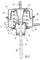
- the charge pressure regulator shown in Figure 1 has a can 1 with an approximately cylindrical or slightly conical peripheral wall 2 and with a bottom 3.
- the can 1 is preferably made of metal and may, for. B. be formed by deep drawing from sheet metal.
- a circular hole 5 In the middle of the bottom 3 is a circular hole 5, which is surrounded by a neck 6, which is U-shaped in radial section, which gives it an increased dimensional stability.
- the neck 6 may be formed by a crimping operation.
- a first sleeve 7 has a cylindrical main part 8, which is bounded on the one hand by a radially inwardly directed flange 9 and on the other hand by a radially outwardly directed flange 10.
- the first sleeve 7 is preferably also a deep-drawn part made of sheet metal.
- a guide bush 11 is arranged on the radially inwardly directed flange 9, which preferably consists of a disc made of a high temperature resistant plastic or of a ceramic.
- the guide bush 11 On its outer side, the guide bush 11 has an annular recess 12, which is open to the flange 9 and the peripheral wall of the main part 8 and an O-ring 13 receives, which bridges the gap between the sleeve 7 and the peripheral wall of the main part 8 and the guide bush 11 limited yielding and vibration damping in the first sleeve 7 fixed.
- the position of the guide bushing 11 can be secured by pressing in the sleeve 7 receiving it.
- a conical centering ring 14 has a radially outwardly directed flange 15, which is fixed to the radially outwardly directed flange 10 of the first sleeve 7 by being flanged and the flange 15 of the centering ring 14 encloses.
- a rolling diaphragm 16, which is preferably formed from an elastomeric plastic, has a radially outwardly directed edge 17 which is clamped between the flange 15 of the centering ring 14 and the radially outwardly directed flange 10 of the first sleeve 7 and by crimping it outwardly directed flange 10 is clamped.
- the outer edge 17 of the rolling diaphragm 16 is thickened. In this way, a waist is formed during the production of the flanging flange 10, which secures the position of the outer edge 17 of the rolling diaphragm 16.
- the rolling diaphragm 16 rests with its central portion of the conical inner side of the centering ring 14 and extends in an arc whose concave side of the guide bush 11 faces, to the shaft 20 of a control rod 18, which is preferably designed as a hex screw, which has a head 19, Subsequently, a cylindrical shaft 20 and then a threaded portion 21 has.
- the rolling diaphragm 16 has a centric hole with a thickened inner edge 22, which abuts the shaft 20 in the immediate vicinity of the head 19 of the control rod 18 with bias.
- the control rod 18 is fixedly connected to a second sleeve 23, which preferably consists of sheet metal, has a cylindrical portion 24 whose inner diameter coincides with the outer diameter of the head 19 of the control rod 18 and has a radially inwardly directed flange 25, which positively behind the head 19 engages and its back rests.
- the radially inwardly directed flange 25 is adjacent to the inner edge 22 portion of the rolling diaphragm 16 at.
- the cylindrical portion 24 of the second sleeve 23 continues via a conical transition portion 26 into a cylindrical portion 27 of larger diameter, to which a neck 28 connects, whose diameter compared to the cylindrical portion 27 is increased again.
- the neck 28 tightly encloses an annular magnet 29 having an axial magnetization direction, i. h., A magnetization direction in the direction of the longitudinal axis 30 of the control rod 18th
- a diaphragm plate 31 has a flat bottom 32 which extends at right angles to the axis 30 of the control rod 18 and has a central hole defined by a neck 33 which abuts the portion 27 of the second sleeve 23 in the immediate vicinity of the neck 28.
- the position of the diaphragm plate 31 is fixed on the second sleeve 23 by a spiral spring 49. You can also z. B. by soldering, welding, gluing or by pressing the neck 33 may be secured to the second sleeve 23.
- the flat section 32 of the diaphragm plate 31 is adjoined by a conically widening section 34, which is directed against the base 3 and is variable in distance therefrom.
- the outer side of the diaphragm plate 31 is located on a membrane 35, which may consist of the same flexible material as the rolling diaphragm 16 and has a central hole which is bounded by a thickened edge 36 which abuts the second sleeve 23 and there by an annular locking plate 37th is fixed, which has a C-shaped profile in the radial section.
- the inner edge 36 of the diaphragm 35 is clamped between the diaphragm plate 31 and the annular locking plate 37.
- the neck 28 of the second sleeve 23 is crimped outwardly at its edge and holds the annular locking plate 37 captive firmly.
- the thickened outer edge 38 of the membrane 35 is clamped between the outer edge 39 of the can 1 and the outer edge 41 of a lid 40 which covers the can 1.
- the lid 40 is in the example shown, a molded part produced by injection molding of plastic, but could also be made of metal.
- the edge 39 of the can 1 is flanged and in this way encloses both the outer edge 38 of the diaphragm 35 and the outer edge 41 of the lid 40.
- the lid 40 has a centric, stepped opening 42 into which a molded part 43 made of plastic is inserted, which closes the opening 42.
- the molded part 43 is formed to the stepped opening 42 suitably stepped, engages positively into the opening 42 and is fixed therein by latching.
- the opening 42 in the lid 40 is provided with a plurality of undercuts 44, only one of which is shown.
- the molding 43 is provided with matching to the undercuts 44 locking hooks 45 which snap behind the undercuts 44 when the molding 43 is inserted into the opening 42 of the lid 40.
- An O-ring 46 seals the gap between the molding 43 and the cover 40 against ingress of moisture.
- the molded part 43 could also be screwed into the cover 40 instead of being locked with it.
- the molded part 43 is part of a housing with an inner space 47 and has a coaxially to the control rod 18 extending extension 48 which projects into the second sleeve 23.
- the spiral spring 49 is clamped between the diaphragm plate 31 and the flanged edge of the first sleeve 7. Its one end is centered by the centering ring 14 and presses the diaphragm plate 31 in the direction against the cover 40. In this case, the diaphragm plate 31, the second sleeve 23 with, until it with its front edge, on which the magnet 29 is disposed on the lid 40th strikes. This position is shown in FIG. 1.
- the charge pressure regulator it is the task of the charge pressure regulator to act by means of the control rod 18 on an exhaust gas turbocharger of a vehicle with an internal combustion engine, in particular with a diesel engine.
- the membrane 35 is acted upon either on its cover 40 facing side with an overpressure or on its side facing the coil spring 49 side with a negative pressure.
- the can 1 is on the can 1
- a first port 50 is provided for connecting a suction line, whereas the cover 40, a second port 51 is provided, to which a pressure relief line can be connected.
- the membrane 35 presses the diaphragm plate 31 away from the cover 40 while compressing the coil spring 49, the space between the diaphragm 35 and the rolling diaphragm 26 decreasing.
- This reduction is achieved in that the membrane 35 extends from the second sleeve 23 to the outer edge of the can 1, whereas the rolling diaphragm 16 extends only from the control rod 18 to the edge of the hole in the bottom 3 of the can 1.
- the required pressure equalization in the chamber between the cover 40 and the flexible diaphragm 35 is carried by the open second port 51. If a positive pressure line is connected to the second port 51, then the overpressure causes a displacement of the diaphragm plate 31 and the control rod 18th away from the lid 40.
- the chamber between the flexible membrane 35 and the rolling diaphragm 16 is vented through the first port 50.
- the chamber between the rolling diaphragm 16 and the guide bush 11 is vented through the guide gap between the guide bushing 11 and the control rod 18.
- the displacement of the diaphragm plate 31 depends on the pressure difference, which prevails on the two sides of the diaphragm 35 and finds its end at the latest when the outer edge of the diaphragm plate 31 abuts the bottom 3 of the can 1.
- the diaphragm plate 31 takes the second sleeve 23 and with it the control rod 18 with.
- a measuring device 52 is provided in the space 47 of the molding 43, which can determine the position of the control rod 18 without contact.
- four Hall sensors 54 are provided on a circuit board 53, which are combined into two pairs 55 and 56, in which two Hall sensors are arranged congruently on the front and on the back of the circuit board 53, wherein the two pairs 55 and 56 in Longitudinal direction of the axis 30 have a distance from each other.
- a voltage signal is generated in these, which sinusoidally or sinusoidally depends on the path of the magnet 29 and thus the path of the control rod 18.
- the two Hall sensors 54 of each pair 55 and 56 are connected together so that the voltage signals generated in them add up.
- FIG. 2 shows the course of the voltage signals as a function of the displacement path of the control rod 18 for the two Hall sensor pairs 55 and 56.
- the required signal evaluation takes place in an electronic circuit not shown in detail, which is housed in the space 47 and preferably equipped with an application-specific integrated circuit 57 (ASIC).
- ASIC application-specific integrated circuit 57
- the arrangement of the flexible membrane 35 and the rolling diaphragm 16 is such that both when applying the boost pressure regulator with excess pressure and when applying the boost pressure regulator with negative pressure, the diaphragm 35 always on the supporting diaphragm plate 31 and the rolling diaphragm 16 on the conical supporting them Centering ring 14 presses. No membrane is ever lifted off. Therefore, neither sealing problems nor special wear problems occur.
- the boost pressure regulator To assemble the boost pressure regulator, one can proceed as follows: In the second sleeve 23 of the annular magnet 29 is used and z. B. fixed by gluing or pressing. The diaphragm plate 31 and the coil spring 40 are pushed to the stop on the sleeve 23 and this to the stop on the control rod 18. The guide bushing 11 is inserted with the O-ring 13 in the first sleeve 7 and the outer edge to form a flanged flange 10 around the outer edge of the rolling diaphragm 16 and the centering ring 14 around crimped.
- the control rod is pushed with its shaft 20 through the hole of the rolling diaphragm 16 and through the guide bush 11 until the inner edge 22 of the rolling diaphragm 16 at the radially inwardly directed flange 25 of the second sleeve 23 is located.
- the centering ring 23 is inserted into the coil spring 40.
- the crimping flange 10 is inserted into the neck 5, which limits the hole in the bottom 3 of the box 1 and welded to the neck 5.
- the membrane 35 is pushed until it rests on the diaphragm plate 31 on the second sleeve 23 and secured by sliding the locking plate 37.
- the outer edge 38 of the membrane 35 is inserted between the edge 41 of the lid 40 and the edge 39 of the box 1 and clamped by crimping the edge 39, wherein at the same time the can 1 and its lid 40 are firmly connected. Finally, the insert 43 is inserted with the measuring device in the lid 40 until his snap hook 45 snap. Most assembly steps are plug-in operations, which simplifies assembly and reduces costs.
- the embodiment shown in Figure 1 can be modified so that it has no measuring device for monitoring the position of the control rod 18. In this case, no housing for receiving the measuring device is required. Instead of the insert 43 can be inserted into the opening 42 of the lid 40 in this case, a blind plug.
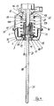
- FIG. 1 Another modification of the embodiment according to FIG. 1 is shown in FIG. In this case, instead of the combination of cover 40 and insert 43, a modified cover 57 is provided, which consists of sheet metal and may be formed as a deep-drawn part.
- the lid 57 includes a second nozzle 51 in a centric arrangement.
- the charge pressure regulator shown in Figure 3 as the charge pressure regulator shown in Figure 1 with overpressure or with Negative pressure to be operated.
- the lid 57 may be made of plastic instead of metal. Since a measuring device for monitoring the position of the control rod 18 is not provided, no magnet is inserted into the second sleeve 23.
- the assembly of the modified boost pressure regulator takes place as in the first embodiment, wherein the mounting of the magnet and the insert with the measuring device omitted.
- the embodiment shown in Figure 4 shows a boost pressure regulator, which is actuated by negative pressure and differs from the charge pressure regulator shown in Figure 1 in that the control rod is not extended under the action of a negative pressure, but retracted, as in boost pressure regulators, which on vacuum react, is common.
- FIG. 4 shows that the invention can also be used with advantage in such boost pressure regulators.
- the basic structure of such a boost pressure regulator without an appealing to the position of the control rod measuring device is from the DE 20 2005 017 296 known. Notwithstanding the embodiment shown in Figure 1, the rolling diaphragm is omitted.
- the can 1 has a conical peripheral portion 4.
- the diaphragm 35 and the diaphragm plate 31 are installed in reverse.
- the diaphragm plate 31 is attached directly to the head 19 of the control rod and additionally secured by a locking ring 58.
- a profiled contour of the diaphragm plate 31 rests positively on a complementary profiled centering sleeve 59 for the coil spring 49.
- the centering sleeve 59 is at the same time carrier of an annular magnet 29, which it receives at its lid 40 facing the end.
- the centering sleeve is a molded part made of plastic, in which the magnet 29 is embedded.
- An annular clip 60 secures the position of the inner edge 36 of the diaphragm 35 in an annular recess of the diaphragm plate 31st
- an annular projection 61 is formed, in which a loose centering ring 14 is inserted for the coil spring 49.
- the centering ring 14 is held in place by the force of the coil spring 49.
- a guide bushing 11 which consists of a high temperature resistant plastic or a ceramic, is used with an O-ring 13 vibration damping in a recess of the bottom 3 of the can 1.
- the diaphragm plate 31 at the head 19 of the control rod 18 and the crimping of the outer edge 39 of the box 1 only plugging operations are required for the assembly of the boost pressure regulator.
- crimping can be the can 1 and the cover 40 by snapping, ie replaced by a simple mating process, thereby further simplify the assembly.
Landscapes
- Engineering & Computer Science (AREA)
- Mechanical Engineering (AREA)
- General Engineering & Computer Science (AREA)
- Chemical & Material Sciences (AREA)
- Combustion & Propulsion (AREA)
- Physics & Mathematics (AREA)
- Fluid Mechanics (AREA)
- Measuring Fluid Pressure (AREA)
- Supercharger (AREA)
Applications Claiming Priority (1)
| Application Number | Priority Date | Filing Date | Title |
|---|---|---|---|
| DE102006021129A DE102006021129B3 (de) | 2006-05-04 | 2006-05-04 | Ladedruckregler für Abgas-Turbolader von Brennkraftmotoren für Automobile |
Publications (3)
| Publication Number | Publication Date |
|---|---|
| EP1852586A2 true EP1852586A2 (fr) | 2007-11-07 |
| EP1852586A3 EP1852586A3 (fr) | 2009-04-22 |
| EP1852586B1 EP1852586B1 (fr) | 2011-09-21 |
Family
ID=38109134
Family Applications (1)
| Application Number | Title | Priority Date | Filing Date |
|---|---|---|---|
| EP07006517A Not-in-force EP1852586B1 (fr) | 2006-05-04 | 2007-03-29 | Régulateur de pression de suralimentation pour turbosoufflante et turbocompresseur de moteurs à combustion interne pour automobile |
Country Status (3)
| Country | Link |
|---|---|
| EP (1) | EP1852586B1 (fr) |
| AT (1) | ATE525557T1 (fr) |
| DE (1) | DE102006021129B3 (fr) |
Families Citing this family (6)
| Publication number | Priority date | Publication date | Assignee | Title |
|---|---|---|---|---|
| DE112008003309T5 (de) | 2007-12-03 | 2010-10-07 | Cts Corp., Elkhart | Linearer Positionssensor |
| WO2010068241A1 (fr) | 2008-11-26 | 2010-06-17 | Cts Corporation | Capteur de position linéaire à dispositif anti-rotation |
| DE112010004761T5 (de) | 2009-12-09 | 2012-11-29 | Cts Corporation | Antriebs- und Sensoranordnung |
| DE202010016534U1 (de) * | 2010-11-30 | 2012-03-06 | Arca Regler Gmbh | Regelventilstelleinrichtung |
| US9435630B2 (en) | 2010-12-08 | 2016-09-06 | Cts Corporation | Actuator and linear position sensor assembly |
| EP2930376A1 (fr) * | 2014-04-11 | 2015-10-14 | Schaeffler Technologies GmbH & Co. KG | Vérin d'actionnement doté d'un système de détection |
Family Cites Families (9)
| Publication number | Priority date | Publication date | Assignee | Title |
|---|---|---|---|---|
| DE7424147U (de) * | 1974-10-10 | Vdo Schindling A Ag | Druckmittelbetätigtes Steuerelement | |
| US3859619A (en) * | 1972-07-11 | 1975-01-07 | Nippon Denso Co | Valve operation detecting device |
| DE3623677C1 (en) * | 1986-07-12 | 1987-04-16 | Daimler Benz Ag | Exhaust gas recirculation device for an internal combustion engine |
| DE19636418C2 (de) * | 1996-09-07 | 1998-06-10 | Kaemmer Ventile Gmbh | Pneumatischer Stellantrieb |
| DE19939497C2 (de) * | 1999-08-20 | 2001-09-27 | Samson Ag | Antrieb eines Stellventils mit Sensiereinheit zur Ventilpositionserfassung |
| DE10027668A1 (de) * | 2000-06-03 | 2001-12-06 | Bosch Gmbh Robert | Vorrichtung zur Steuerung der Verdichterleistung eines an eine Brennkraftmaschine angeschlossenen Abgasturboladers |
| DE10304551A1 (de) * | 2003-02-04 | 2004-08-12 | Mann + Hummel Gmbh | Stellelement mit Lageerkennung |
| ITAR20030013U1 (it) * | 2003-06-12 | 2003-09-10 | Faist Componenti S P A | Attuatore pneumatico con rilevatore di posizione elettrico |
| DE202005017296U1 (de) * | 2005-03-03 | 2006-02-02 | Smk Systeme Metall Kunststoff Gmbh & Co. | Ladedruckregler für Abgas-Turbolader von Brennkraftmotoren für Automobile |
-
2006
- 2006-05-04 DE DE102006021129A patent/DE102006021129B3/de not_active Expired - Fee Related
-
2007
- 2007-03-29 EP EP07006517A patent/EP1852586B1/fr not_active Not-in-force
- 2007-03-29 AT AT07006517T patent/ATE525557T1/de active
Also Published As
| Publication number | Publication date |
|---|---|
| EP1852586B1 (fr) | 2011-09-21 |
| EP1852586A3 (fr) | 2009-04-22 |
| ATE525557T1 (de) | 2011-10-15 |
| DE102006021129B3 (de) | 2007-06-28 |
Similar Documents
| Publication | Publication Date | Title |
|---|---|---|
| EP1852588B1 (fr) | Régulateur de pression de suralimentation pour turbosoufflante et turbocompresseur de moteurs à combustion interne pour automobile | |
| EP1852587B1 (fr) | Régulateur de pression de suralimentation pour turbocompresseur de moteurs à combustion interne pour automobile | |
| EP1852586B1 (fr) | Régulateur de pression de suralimentation pour turbosoufflante et turbocompresseur de moteurs à combustion interne pour automobile | |
| DE10242841B4 (de) | Ausrücklager für eine Kupplung mit einem Magnetgeber | |
| DE112010004761T5 (de) | Antriebs- und Sensoranordnung | |
| DE112008003309T5 (de) | Linearer Positionssensor | |
| DE102010006058A1 (de) | Hydraulisches Kupplungs- oder Bremsbetätigungssystem | |
| EP1627212B1 (fr) | Capteur dynamometrique | |
| EP1391615B1 (fr) | Unité de piston-cylindre | |
| DE102005010982A1 (de) | Kraftmesszelle | |
| EP3772595A1 (fr) | Unité de capteur pour cylindre fluidique et cylindre fluidique | |
| WO2004083792A1 (fr) | Cellule dynamometrique | |
| DE102017111083B3 (de) | Kupplungsnehmerzylinder mit integrierter Wegmessung | |
| DE202006007250U1 (de) | Ladedruckregler für Abgas-Turbolader von Brennkraftmotoren für Automobile | |
| DE202006007251U1 (de) | Ladedruckregler für Abgas-Turbolader von Brennkraftmotoren für Automobile | |
| DE102018001752B4 (de) | Zentralausrücker für eine pneumatische Kupplungsbetätigung | |
| EP1249620A1 (fr) | Capteur de position pour actionneur linéaire | |
| DE202006007249U1 (de) | Ladedruckregler zur Abgas-Turbolader von Brennkraftmotoren für Automobile | |
| EP1339586A1 (fr) | Dispositif capteur pour un servofrein a depression et servofrein a depression equipe dudit capteur | |
| DE102018125840A1 (de) | Tool Center Point | |
| DE102017112069A1 (de) | Zentralausrücker mit in Gehäuse einschiebbarem Sensor, Zentralausrücker mit Kolben und daran befestigtem Magneten und Montageverfahren | |
| DE10026082C1 (de) | Vorrichtung zur Befestigung eines Sensors an einem Druckmittelzylinder | |
| EP4323727B1 (fr) | Système électromagnétique de mesure de course d'un piston, support d'aimant ainsi qu'utilisation d'un système électromagnétique de mesure de course d'un piston | |
| DE102020118052A1 (de) | Betätigungsvorrichtung für ein automatisiertes Schaltgetriebe | |
| EP0954099B1 (fr) | Interrupteur à pression |
Legal Events
| Date | Code | Title | Description |
|---|---|---|---|
| PUAI | Public reference made under article 153(3) epc to a published international application that has entered the european phase |
Free format text: ORIGINAL CODE: 0009012 |
|
| AK | Designated contracting states |
Kind code of ref document: A2 Designated state(s): AT BE BG CH CY CZ DE DK EE ES FI FR GB GR HU IE IS IT LI LT LU LV MC MT NL PL PT RO SE SI SK TR |
|
| AX | Request for extension of the european patent |
Extension state: AL BA HR MK YU |
|
| PUAL | Search report despatched |
Free format text: ORIGINAL CODE: 0009013 |
|
| AK | Designated contracting states |
Kind code of ref document: A3 Designated state(s): AT BE BG CH CY CZ DE DK EE ES FI FR GB GR HU IE IS IT LI LT LU LV MC MT NL PL PT RO SE SI SK TR |
|
| AX | Request for extension of the european patent |
Extension state: AL BA HR MK RS |
|
| 17P | Request for examination filed |
Effective date: 20091008 |
|
| 17Q | First examination report despatched |
Effective date: 20091109 |
|
| AKX | Designation fees paid |
Designated state(s): AT BE BG CH CY CZ DE DK EE ES FI FR GB GR HU IE IS IT LI LT LU LV MC MT NL PL PT RO SE SI SK TR |
|
| GRAP | Despatch of communication of intention to grant a patent |
Free format text: ORIGINAL CODE: EPIDOSNIGR1 |
|
| GRAS | Grant fee paid |
Free format text: ORIGINAL CODE: EPIDOSNIGR3 |
|
| GRAA | (expected) grant |
Free format text: ORIGINAL CODE: 0009210 |
|
| AK | Designated contracting states |
Kind code of ref document: B1 Designated state(s): AT BE BG CH CY CZ DE DK EE ES FI FR GB GR HU IE IS IT LI LT LU LV MC MT NL PL PT RO SE SI SK TR |
|
| REG | Reference to a national code |
Ref country code: GB Ref legal event code: FG4D Free format text: NOT ENGLISH |
|
| REG | Reference to a national code |
Ref country code: CH Ref legal event code: EP |
|
| REG | Reference to a national code |
Ref country code: IE Ref legal event code: FG4D Free format text: LANGUAGE OF EP DOCUMENT: GERMAN |
|
| REG | Reference to a national code |
Ref country code: DE Ref legal event code: R096 Ref document number: 502007008187 Country of ref document: DE Effective date: 20111117 |
|
| REG | Reference to a national code |
Ref country code: NL Ref legal event code: VDEP Effective date: 20110921 |
|
| PG25 | Lapsed in a contracting state [announced via postgrant information from national office to epo] |
Ref country code: FI Free format text: LAPSE BECAUSE OF FAILURE TO SUBMIT A TRANSLATION OF THE DESCRIPTION OR TO PAY THE FEE WITHIN THE PRESCRIBED TIME-LIMIT Effective date: 20110921 Ref country code: SE Free format text: LAPSE BECAUSE OF FAILURE TO SUBMIT A TRANSLATION OF THE DESCRIPTION OR TO PAY THE FEE WITHIN THE PRESCRIBED TIME-LIMIT Effective date: 20110921 Ref country code: LT Free format text: LAPSE BECAUSE OF FAILURE TO SUBMIT A TRANSLATION OF THE DESCRIPTION OR TO PAY THE FEE WITHIN THE PRESCRIBED TIME-LIMIT Effective date: 20110921 |
|
| LTIE | Lt: invalidation of european patent or patent extension |
Effective date: 20110921 |
|
| PG25 | Lapsed in a contracting state [announced via postgrant information from national office to epo] |
Ref country code: LV Free format text: LAPSE BECAUSE OF FAILURE TO SUBMIT A TRANSLATION OF THE DESCRIPTION OR TO PAY THE FEE WITHIN THE PRESCRIBED TIME-LIMIT Effective date: 20110921 Ref country code: SI Free format text: LAPSE BECAUSE OF FAILURE TO SUBMIT A TRANSLATION OF THE DESCRIPTION OR TO PAY THE FEE WITHIN THE PRESCRIBED TIME-LIMIT Effective date: 20110921 Ref country code: CY Free format text: LAPSE BECAUSE OF FAILURE TO SUBMIT A TRANSLATION OF THE DESCRIPTION OR TO PAY THE FEE WITHIN THE PRESCRIBED TIME-LIMIT Effective date: 20110921 Ref country code: GR Free format text: LAPSE BECAUSE OF FAILURE TO SUBMIT A TRANSLATION OF THE DESCRIPTION OR TO PAY THE FEE WITHIN THE PRESCRIBED TIME-LIMIT Effective date: 20111222 |
|
| REG | Reference to a national code |
Ref country code: IE Ref legal event code: FD4D |
|
| PG25 | Lapsed in a contracting state [announced via postgrant information from national office to epo] |
Ref country code: IE Free format text: LAPSE BECAUSE OF FAILURE TO SUBMIT A TRANSLATION OF THE DESCRIPTION OR TO PAY THE FEE WITHIN THE PRESCRIBED TIME-LIMIT Effective date: 20110921 Ref country code: CZ Free format text: LAPSE BECAUSE OF FAILURE TO SUBMIT A TRANSLATION OF THE DESCRIPTION OR TO PAY THE FEE WITHIN THE PRESCRIBED TIME-LIMIT Effective date: 20110921 Ref country code: SK Free format text: LAPSE BECAUSE OF FAILURE TO SUBMIT A TRANSLATION OF THE DESCRIPTION OR TO PAY THE FEE WITHIN THE PRESCRIBED TIME-LIMIT Effective date: 20110921 Ref country code: IS Free format text: LAPSE BECAUSE OF FAILURE TO SUBMIT A TRANSLATION OF THE DESCRIPTION OR TO PAY THE FEE WITHIN THE PRESCRIBED TIME-LIMIT Effective date: 20120121 |
|
| PG25 | Lapsed in a contracting state [announced via postgrant information from national office to epo] |
Ref country code: RO Free format text: LAPSE BECAUSE OF FAILURE TO SUBMIT A TRANSLATION OF THE DESCRIPTION OR TO PAY THE FEE WITHIN THE PRESCRIBED TIME-LIMIT Effective date: 20110921 Ref country code: PL Free format text: LAPSE BECAUSE OF FAILURE TO SUBMIT A TRANSLATION OF THE DESCRIPTION OR TO PAY THE FEE WITHIN THE PRESCRIBED TIME-LIMIT Effective date: 20110921 Ref country code: PT Free format text: LAPSE BECAUSE OF FAILURE TO SUBMIT A TRANSLATION OF THE DESCRIPTION OR TO PAY THE FEE WITHIN THE PRESCRIBED TIME-LIMIT Effective date: 20120123 Ref country code: NL Free format text: LAPSE BECAUSE OF FAILURE TO SUBMIT A TRANSLATION OF THE DESCRIPTION OR TO PAY THE FEE WITHIN THE PRESCRIBED TIME-LIMIT Effective date: 20110921 Ref country code: IT Free format text: LAPSE BECAUSE OF FAILURE TO SUBMIT A TRANSLATION OF THE DESCRIPTION OR TO PAY THE FEE WITHIN THE PRESCRIBED TIME-LIMIT Effective date: 20110921 Ref country code: EE Free format text: LAPSE BECAUSE OF FAILURE TO SUBMIT A TRANSLATION OF THE DESCRIPTION OR TO PAY THE FEE WITHIN THE PRESCRIBED TIME-LIMIT Effective date: 20110921 |
|
| PLBE | No opposition filed within time limit |
Free format text: ORIGINAL CODE: 0009261 |
|
| STAA | Information on the status of an ep patent application or granted ep patent |
Free format text: STATUS: NO OPPOSITION FILED WITHIN TIME LIMIT |
|
| PG25 | Lapsed in a contracting state [announced via postgrant information from national office to epo] |
Ref country code: DK Free format text: LAPSE BECAUSE OF FAILURE TO SUBMIT A TRANSLATION OF THE DESCRIPTION OR TO PAY THE FEE WITHIN THE PRESCRIBED TIME-LIMIT Effective date: 20110921 |
|
| 26N | No opposition filed |
Effective date: 20120622 |
|
| BERE | Be: lapsed |
Owner name: SMK SYSTEME METALL KUNSTSTOFF G.M.B.H. & CO. KG. Effective date: 20120331 |
|
| REG | Reference to a national code |
Ref country code: DE Ref legal event code: R097 Ref document number: 502007008187 Country of ref document: DE Effective date: 20120622 |
|
| PG25 | Lapsed in a contracting state [announced via postgrant information from national office to epo] |
Ref country code: MC Free format text: LAPSE BECAUSE OF NON-PAYMENT OF DUE FEES Effective date: 20120331 |
|
| REG | Reference to a national code |
Ref country code: CH Ref legal event code: PL |
|
| GBPC | Gb: european patent ceased through non-payment of renewal fee |
Effective date: 20120329 |
|
| REG | Reference to a national code |
Ref country code: FR Ref legal event code: ST Effective date: 20121130 |
|
| PG25 | Lapsed in a contracting state [announced via postgrant information from national office to epo] |
Ref country code: FR Free format text: LAPSE BECAUSE OF NON-PAYMENT OF DUE FEES Effective date: 20120402 Ref country code: CH Free format text: LAPSE BECAUSE OF NON-PAYMENT OF DUE FEES Effective date: 20120331 Ref country code: GB Free format text: LAPSE BECAUSE OF NON-PAYMENT OF DUE FEES Effective date: 20120329 Ref country code: LI Free format text: LAPSE BECAUSE OF NON-PAYMENT OF DUE FEES Effective date: 20120331 Ref country code: BE Free format text: LAPSE BECAUSE OF NON-PAYMENT OF DUE FEES Effective date: 20120331 |
|
| PG25 | Lapsed in a contracting state [announced via postgrant information from national office to epo] |
Ref country code: ES Free format text: LAPSE BECAUSE OF FAILURE TO SUBMIT A TRANSLATION OF THE DESCRIPTION OR TO PAY THE FEE WITHIN THE PRESCRIBED TIME-LIMIT Effective date: 20120101 |
|
| REG | Reference to a national code |
Ref country code: AT Ref legal event code: MM01 Ref document number: 525557 Country of ref document: AT Kind code of ref document: T Effective date: 20120329 |
|
| PG25 | Lapsed in a contracting state [announced via postgrant information from national office to epo] |
Ref country code: BG Free format text: LAPSE BECAUSE OF FAILURE TO SUBMIT A TRANSLATION OF THE DESCRIPTION OR TO PAY THE FEE WITHIN THE PRESCRIBED TIME-LIMIT Effective date: 20111221 |
|
| PG25 | Lapsed in a contracting state [announced via postgrant information from national office to epo] |
Ref country code: MT Free format text: LAPSE BECAUSE OF FAILURE TO SUBMIT A TRANSLATION OF THE DESCRIPTION OR TO PAY THE FEE WITHIN THE PRESCRIBED TIME-LIMIT Effective date: 20110921 Ref country code: AT Free format text: LAPSE BECAUSE OF NON-PAYMENT OF DUE FEES Effective date: 20120329 |
|
| PG25 | Lapsed in a contracting state [announced via postgrant information from national office to epo] |
Ref country code: TR Free format text: LAPSE BECAUSE OF FAILURE TO SUBMIT A TRANSLATION OF THE DESCRIPTION OR TO PAY THE FEE WITHIN THE PRESCRIBED TIME-LIMIT Effective date: 20110921 |
|
| PG25 | Lapsed in a contracting state [announced via postgrant information from national office to epo] |
Ref country code: LU Free format text: LAPSE BECAUSE OF NON-PAYMENT OF DUE FEES Effective date: 20120329 |
|
| PG25 | Lapsed in a contracting state [announced via postgrant information from national office to epo] |
Ref country code: HU Free format text: LAPSE BECAUSE OF FAILURE TO SUBMIT A TRANSLATION OF THE DESCRIPTION OR TO PAY THE FEE WITHIN THE PRESCRIBED TIME-LIMIT Effective date: 20070329 |
|
| REG | Reference to a national code |
Ref country code: DE Ref legal event code: R082 Ref document number: 502007008187 Country of ref document: DE Representative=s name: KOHLER SCHMID MOEBUS PATENTANWAELTE, DE Ref country code: DE Ref legal event code: R082 Ref document number: 502007008187 Country of ref document: DE Representative=s name: KOHLER SCHMID MOEBUS PATENTANWAELTE PARTNERSCH, DE |
|
| PGFP | Annual fee paid to national office [announced via postgrant information from national office to epo] |
Ref country code: DE Payment date: 20160326 Year of fee payment: 10 |
|
| REG | Reference to a national code |
Ref country code: DE Ref legal event code: R119 Ref document number: 502007008187 Country of ref document: DE |
|
| PG25 | Lapsed in a contracting state [announced via postgrant information from national office to epo] |
Ref country code: DE Free format text: LAPSE BECAUSE OF NON-PAYMENT OF DUE FEES Effective date: 20171003 |