EP1852604A1 - Procédé de fonctionnement de bougies dans des moteurs diesel - Google Patents
Procédé de fonctionnement de bougies dans des moteurs diesel Download PDFInfo
- Publication number
- EP1852604A1 EP1852604A1 EP07008993A EP07008993A EP1852604A1 EP 1852604 A1 EP1852604 A1 EP 1852604A1 EP 07008993 A EP07008993 A EP 07008993A EP 07008993 A EP07008993 A EP 07008993A EP 1852604 A1 EP1852604 A1 EP 1852604A1
- Authority
- EP
- European Patent Office
- Prior art keywords
- temperature
- glow
- engine
- control unit
- glow plug
- Prior art date
- Legal status (The legal status is an assumption and is not a legal conclusion. Google has not performed a legal analysis and makes no representation as to the accuracy of the status listed.)
- Granted
Links
Images
Classifications
-
- F—MECHANICAL ENGINEERING; LIGHTING; HEATING; WEAPONS; BLASTING
- F02—COMBUSTION ENGINES; HOT-GAS OR COMBUSTION-PRODUCT ENGINE PLANTS
- F02P—IGNITION, OTHER THAN COMPRESSION IGNITION, FOR INTERNAL-COMBUSTION ENGINES; TESTING OF IGNITION TIMING IN COMPRESSION-IGNITION ENGINES
- F02P19/00—Incandescent ignition, e.g. during starting of internal combustion engines; Combination of incandescent and spark ignition
- F02P19/02—Incandescent ignition, e.g. during starting of internal combustion engines; Combination of incandescent and spark ignition electric, e.g. layout of circuits of apparatus having glowing plugs
- F02P19/026—Glow plug actuation during engine operation
-
- F—MECHANICAL ENGINEERING; LIGHTING; HEATING; WEAPONS; BLASTING
- F02—COMBUSTION ENGINES; HOT-GAS OR COMBUSTION-PRODUCT ENGINE PLANTS
- F02P—IGNITION, OTHER THAN COMPRESSION IGNITION, FOR INTERNAL-COMBUSTION ENGINES; TESTING OF IGNITION TIMING IN COMPRESSION-IGNITION ENGINES
- F02P19/00—Incandescent ignition, e.g. during starting of internal combustion engines; Combination of incandescent and spark ignition
-
- F—MECHANICAL ENGINEERING; LIGHTING; HEATING; WEAPONS; BLASTING
- F02—COMBUSTION ENGINES; HOT-GAS OR COMBUSTION-PRODUCT ENGINE PLANTS
- F02D—CONTROLLING COMBUSTION ENGINES
- F02D41/00—Electrical control of supply of combustible mixture or its constituents
- F02D41/02—Circuit arrangements for generating control signals
- F02D41/021—Introducing corrections for particular conditions exterior to the engine
- F02D41/0235—Introducing corrections for particular conditions exterior to the engine in relation with the state of the exhaust gas treating apparatus
- F02D41/024—Introducing corrections for particular conditions exterior to the engine in relation with the state of the exhaust gas treating apparatus to increase temperature of the exhaust gas treating apparatus
- F02D2041/026—Introducing corrections for particular conditions exterior to the engine in relation with the state of the exhaust gas treating apparatus to increase temperature of the exhaust gas treating apparatus using an external load, e.g. by increasing generator load or by changing the gear ratio
-
- F—MECHANICAL ENGINEERING; LIGHTING; HEATING; WEAPONS; BLASTING
- F02—COMBUSTION ENGINES; HOT-GAS OR COMBUSTION-PRODUCT ENGINE PLANTS
- F02D—CONTROLLING COMBUSTION ENGINES
- F02D2200/00—Input parameters for engine control
- F02D2200/02—Input parameters for engine control the parameters being related to the engine
- F02D2200/023—Temperature of lubricating oil or working fluid
-
- F—MECHANICAL ENGINEERING; LIGHTING; HEATING; WEAPONS; BLASTING
- F02—COMBUSTION ENGINES; HOT-GAS OR COMBUSTION-PRODUCT ENGINE PLANTS
- F02D—CONTROLLING COMBUSTION ENGINES
- F02D2200/00—Input parameters for engine control
- F02D2200/02—Input parameters for engine control the parameters being related to the engine
- F02D2200/04—Engine intake system parameters
- F02D2200/0414—Air temperature
-
- F—MECHANICAL ENGINEERING; LIGHTING; HEATING; WEAPONS; BLASTING
- F02—COMBUSTION ENGINES; HOT-GAS OR COMBUSTION-PRODUCT ENGINE PLANTS
- F02D—CONTROLLING COMBUSTION ENGINES
- F02D41/00—Electrical control of supply of combustible mixture or its constituents
- F02D41/02—Circuit arrangements for generating control signals
- F02D41/021—Introducing corrections for particular conditions exterior to the engine
- F02D41/0235—Introducing corrections for particular conditions exterior to the engine in relation with the state of the exhaust gas treating apparatus
- F02D41/024—Introducing corrections for particular conditions exterior to the engine in relation with the state of the exhaust gas treating apparatus to increase temperature of the exhaust gas treating apparatus
- F02D41/0245—Introducing corrections for particular conditions exterior to the engine in relation with the state of the exhaust gas treating apparatus to increase temperature of the exhaust gas treating apparatus by increasing temperature of the exhaust gas leaving the engine
-
- F—MECHANICAL ENGINEERING; LIGHTING; HEATING; WEAPONS; BLASTING
- F02—COMBUSTION ENGINES; HOT-GAS OR COMBUSTION-PRODUCT ENGINE PLANTS
- F02D—CONTROLLING COMBUSTION ENGINES
- F02D41/00—Electrical control of supply of combustible mixture or its constituents
- F02D41/02—Circuit arrangements for generating control signals
- F02D41/04—Introducing corrections for particular operating conditions
- F02D41/06—Introducing corrections for particular operating conditions for engine starting or warming up
- F02D41/062—Introducing corrections for particular operating conditions for engine starting or warming up for starting
- F02D41/064—Introducing corrections for particular operating conditions for engine starting or warming up for starting at cold start
-
- F—MECHANICAL ENGINEERING; LIGHTING; HEATING; WEAPONS; BLASTING
- F02—COMBUSTION ENGINES; HOT-GAS OR COMBUSTION-PRODUCT ENGINE PLANTS
- F02D—CONTROLLING COMBUSTION ENGINES
- F02D41/00—Electrical control of supply of combustible mixture or its constituents
- F02D41/02—Circuit arrangements for generating control signals
- F02D41/04—Introducing corrections for particular operating conditions
- F02D41/12—Introducing corrections for particular operating conditions for deceleration
-
- F—MECHANICAL ENGINEERING; LIGHTING; HEATING; WEAPONS; BLASTING
- F02—COMBUSTION ENGINES; HOT-GAS OR COMBUSTION-PRODUCT ENGINE PLANTS
- F02P—IGNITION, OTHER THAN COMPRESSION IGNITION, FOR INTERNAL-COMBUSTION ENGINES; TESTING OF IGNITION TIMING IN COMPRESSION-IGNITION ENGINES
- F02P19/00—Incandescent ignition, e.g. during starting of internal combustion engines; Combination of incandescent and spark ignition
- F02P19/02—Incandescent ignition, e.g. during starting of internal combustion engines; Combination of incandescent and spark ignition electric, e.g. layout of circuits of apparatus having glowing plugs
- F02P19/025—Incandescent ignition, e.g. during starting of internal combustion engines; Combination of incandescent and spark ignition electric, e.g. layout of circuits of apparatus having glowing plugs with means for determining glow plug temperature or glow plug resistance
Definitions
- the invention is based on a method having the features specified in the preamble of claim 1. Such a method is in the article "The electronically controlled glow system ISS for diesel engines, published in the DE-Z MTZ Motortechnische Zeitschrift 61, (2000) 10, pp. 668-675 , known.
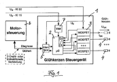
- FIG. 1 shows the block diagram of a glow plug control unit 1 for carrying out the known method.
- This control unit includes a microprocessor 2 with integrated digital-to-analog converter, a number of MOSFET power semiconductor 3 for switching on and off an equal number of glow plugs 4, an electrical interface 5 for connection to a motor control unit 6 and an internal power supply 7 for the microprocessor 2 and for the interface 5.
- the internal power supply 7 has connection with the vehicle battery via the "terminal 15" of the vehicle.
- the microprocessor 2 controls the power semiconductors 3, reads their status information and communicates via the electrical interface 5 with the engine control unit 6.
- the interface 5 makes an adjustment of the signals required for communication between the engine control unit 6 and the microprocessor 2.
- the power supply 7 supplies a stable voltage for the microprocessor 2 and for the interface 5.
- Glow plugs have the task of causing a cold start of the diesel engine, a secure ignition of the fuel-air mixture and then effect in a Nachglühphase a smooth running of the diesel engine until it is so warm that it runs evenly without support by glow plugs ,
- the afterglow phase lasts up to several minutes.
- the glow plug should assume a constant temperature, the steady-state temperature, for which with steel glow plugs approximately 1000 ° C is a typical value.
- modern glow plugs do not require the full voltage from the vehicle electrical system, but only a voltage of typically 5 volts to 6 volts.
- the microprocessor 2 controls the power semiconductors 3 for this purpose by a method of pulse width modulation, with the result that the voltage from the electrical system, which is the power semiconductors 3 via the "terminal 30" of the vehicle is modulated so that the desired voltage is applied to the glow plugs in the time average.
- the control unit 1 supplies the glow plugs 4 with a higher heating voltage of, for example, 11 volts in order to achieve a temperature of the glow plugs as quickly as possible in the amount of steady-state temperature or - preferably - still some 10 ° C temporarily.
- the rapid heating of the glow plugs in the pre-glow phase is energy-controlled, ie, the respective glow plug is supplied with an energy which is predetermined so that the steady-state temperature is reached in any case.
- the steady-state temperature is initially exceeded once and then decreases to the steady-state temperature.
- the engine After a cold start, the engine is for a certain period of time in the so-called cold run phase, which is characterized by an idle speed, which is above the idle speed with warm engine.
- the effective voltage applied to the glow plugs i.e. the voltage averaged over time due to pulse width modulation, is determined by the initial heating voltage of e.g. 11 volts (the "initial value") gradually lowered to a voltage of e.g. 6 volts (the "final value" of the voltage) at which the steady state temperature of the glow plugs of e.g. 1000 ° C can be maintained. Fluctuations in the vehicle electrical system voltage can be compensated during pulse width modulation by changing the switch-on time.
- the gradual lowering of the voltage applied in the mean time to the glow plugs 4 voltage in the cold running phase takes place during a predetermined period of time according to empirical values that are stored in the microprocessor 2.
- the period of time during which the effective stress is raised in the cold-running phase is at most as long as the cold-running phase itself, preferably shorter than this.
- the glow plugs are cooled to different degrees.
- the electric power supplied to the glow plugs is adjusted to the changing conditions. This is done in accordance with the specifications of the engine control unit 6 by raising or lowering the final value of the voltage applied to the glow plugs 4 on average over time.
- the engine control unit decides on the basis of evaluations that it makes itself, when annealing processes are triggered and how long they last.
- the engine control unit has an intelligence that is exercised by means of a state machine, which is integrated in the engine control unit.
- the state machine operates according to a rigid, fixed scheme and generates command signals which are transmitted to the usually mounted on the engine block glow plug control unit, which implements the specification of the engine control unit and taking into account a stored in the glow plug control unit Model of the glow plugs controls the electrical power supplied to the glow plugs. This requires a mutual adaptation of the two control devices and the algorithms running in them, as far as they relate to the control of the glow plugs.
- the present invention has for its object to reduce the cost of realizing the control of glow plugs.
- the inventive method for operating glow plugs which have a housing and a projecting over the housing glow element, in a diesel engine, which cooperates with a motor control unit and a glow plug control device, which following a Vorglühphase the glow plugs supplied electrical power in response to a Controlled by the engine control unit specification is controlled, characterized in that the engine control unit determines a size which is a measure of a temperature that is to occur on the glow element.
- This quantity is transmitted by the engine control unit as a target to the glow plug control device, which converts this target specification with an algorithm stored in the glow plug control device and taking account of characteristic values which are likewise stored in the glow plug control device.
- the engine control unit determines the target temperature for the glow element of the glow plug in an advantageous manner depending on the operating state of the diesel engine. It is not only a consideration of the current operating condition of the diesel engine in question, but also the previous development of the operating condition of the diesel engine, which can observe the engine control unit with the aid of sensors associated with it, be taken into account in determining the target for the temperature. This allows a faster response to changes in the operating state of the diesel engine, which can be predicted based on the observed past development even for a certain period of time.
- the effectiveness of a glow plug depends primarily on the surface temperature of the glow element of the glow plugs.
- the surface temperature is therefore the primary objective for the specification to be determined by the engine control unit.
- the surface temperature of the glow element of the glow plugs can not be measured directly in the diesel engine.
- the glow plug controller includes the type of engine, the glow plug type, the electrical resistance of the glow plugs at a reference temperature, the dependence of the electrical resistance of the glow plug on the temperature
- the heat capacity of the glow plugs the cooling behavior of the glow plugs in dependence on the speed of the engine, the coolant temperature and the sign of a speed change of the engine, and the heat supply from burns under one or more selected load conditions of the engine.
- Limit and threshold values which limit the conversion of the target specification transmitted by the engine control unit in the annealing control unit can also be taken into account with advantage; so z.
- Example be ensured that a transmitted from the engine control unit target for the temperature of the heating element, which would overload the glow plugs used, is limited to a value that is still beneficial for the glow plugs used.
- the target of the engine control unit for the temperature of the glow element can therefore be interpreted in an advantageous development of the invention of the glow plug control and adapted to the type of glow plug used after the glow plug control device has determined himself or he has been entered the glow plug control unit.
- the adaptation may be an increase or decrease in the temperature specification and a change in the temperature curve leading thereto, which could be determined from a pattern characteristic curve of a glow plug stored in the glow controller by modifying the pattern characteristic.
- the coolant temperature can be used to form a limit, z. B. in such a way that a target of the engine control unit for a higher glow plug temperature is disregarded to protect the glow plugs when and as long as the coolant temperature exceeds a threshold.
- the glow plug control device can take into account in the implementation of the target with advantage parameters which are supplied to it from the outside, preferably from the engine control unit, namely z.
- the fuel injection rate per clock the coolant temperature, the speed of the diesel engine, the sign of a speed change of the diesel engine and the temperature of the incoming into the cylinder of the diesel engine combustion air.
- the Glüh horrinology can also the maximum possible temperature z. B. consider when using steel glow plugs. It may limit or interpret the predetermined temperature based on the type of glow plug detected or communicated by the glow controller.
- the target value for the temperature of the glow element is determined by the engine control unit so that a basic temperature for the afterglow phase is initially set and that a lower temperature than the base temperature in one or more of the following cases is specified as a target:
- the diesel engine is in overrun mode ( in this case, the fuel supply may be switched off);
- the coolant temperature exceeds a threshold (the higher the coolant temperature, the more likely it is possible to dispense with hot glow plug combustion support);
- the temperature of the combustion air entering the cylinders exceeds a threshold (an increase in the temperature of the combustion air increases the ignitability of the mixture and allows the glow plug temperature to be lowered);
- the voltage of the electrical power source present in the vehicle (vehicle electrical system voltage) falls below a limit (as a precaution, the current drain from the vehicle electrical system is limited if this is too weak).
- a higher temperature than the previously specified by the engine control unit temperature can from the engine control unit z. B. be given if one or more of the following cases exist:
- the pollutant content in the exhaust gas of the diesel engine exceeds one or more limits (in this case, an increase in the Glow plug temperature to assist combustion); a coasting phase of the diesel engine is ended (the glow plug, which has become colder during the coasting phase, is reheated for the following load case); the coolant temperature falls below a threshold as it occurs in prolonged stop-and-go operation (an increase in the glow plug temperature promotes combustion and reduces pollutant emissions, which is particularly important in city traffic); the temperature of the combustion air entering the cylinders falls below a threshold (an increase in the glow plug temperature promotes combustion and reduces pollutant emissions); the fuel injection amount or load of the diesel engine increases and / or exceeds a threshold (the glow plug may act to assist combustion at least temporarily with combustion support); during annealing to assist the regeneration of a particulate filter present in the exhaust line of the
- a matrix of correction values can be stored in the glow plug control device with which the supply of electrical energy to a glow plug intended for a standard case is corrected as a function of the rotational speed and the instantaneous fuel consumption (eg in mm 3 per stroke).
- the matrix contains the correction values for discrete value pairs of speed and consumption. The energy supply to the glow plugs tends to increase with increasing speed and decreases with increasing consumption.
- the model of the glow plugs stored in the glow plug control unit in the form of characteristic values, characteristic feathers and their behavior in the diesel engine allows the glow plug control device to implement the target of the engine control unit for the temperature of the glow plug of the glow plugs in an open control loop.
Landscapes
- Engineering & Computer Science (AREA)
- Chemical & Material Sciences (AREA)
- Combustion & Propulsion (AREA)
- Mechanical Engineering (AREA)
- General Engineering & Computer Science (AREA)
- Combined Controls Of Internal Combustion Engines (AREA)
- Electrical Control Of Air Or Fuel Supplied To Internal-Combustion Engine (AREA)
- Ignition Installations For Internal Combustion Engines (AREA)
Applications Claiming Priority (1)
| Application Number | Priority Date | Filing Date | Title |
|---|---|---|---|
| DE102006021285.1A DE102006021285B4 (de) | 2006-05-05 | 2006-05-05 | Verfahren zum Betreiben von Glühkerzen in Dieselmotoren |
Publications (2)
| Publication Number | Publication Date |
|---|---|
| EP1852604A1 true EP1852604A1 (fr) | 2007-11-07 |
| EP1852604B1 EP1852604B1 (fr) | 2019-05-15 |
Family
ID=38325230
Family Applications (1)
| Application Number | Title | Priority Date | Filing Date |
|---|---|---|---|
| EP07008993.3A Active EP1852604B1 (fr) | 2006-05-05 | 2007-05-04 | Procédé de fonctionnement de bougies dans des moteurs diesel |
Country Status (4)
| Country | Link |
|---|---|
| US (1) | US7730864B2 (fr) |
| EP (1) | EP1852604B1 (fr) |
| KR (1) | KR101188583B1 (fr) |
| DE (1) | DE102006021285B4 (fr) |
Cited By (8)
| Publication number | Priority date | Publication date | Assignee | Title |
|---|---|---|---|---|
| WO2009000614A1 (fr) * | 2007-06-28 | 2008-12-31 | Robert Bosch Gmbh | Procédé et dispositif pour commander une température de post-chauffage dans un moteur à combustion interne diesel |
| DE102008040971A1 (de) | 2008-08-04 | 2010-02-18 | Robert Bosch Gmbh | Verfahren und Vorrichtung zum Regeln der Temperatur von Glühstiftkerzen in einer Brennkraftmaschine |
| EP2012002A3 (fr) * | 2007-07-06 | 2010-03-24 | BERU Aktiengesellschaft SUE | Procédé de fonctionnement de bougies de préchauffage dans des moteurs diesel |
| FR2960031A1 (fr) * | 2010-05-12 | 2011-11-18 | Peugeot Citroen Automobiles Sa | Procede de commande des bougies de prechauffage d'un moteur |
| EP2314922A4 (fr) * | 2008-07-03 | 2013-05-01 | Bosch Corp | Procédé de commande d'actionnement pour bougie à incandescence |
| EP2128428A3 (fr) * | 2008-05-30 | 2015-07-29 | NGK Spark Plug Co., Ltd. | Appareil et système de contrôle de l'électrification de bougie de préchauffage |
| EP2535545A4 (fr) * | 2010-02-08 | 2018-03-07 | Toyota Jidosha Kabushiki Kaisha | Dispositif de commande de la combustion pour un moteur à combustion interne |
| CN111595488A (zh) * | 2020-04-15 | 2020-08-28 | 岭东核电有限公司 | 核电站柴油机油温检测方法、装置、终端设备及存储介质 |
Families Citing this family (18)
| Publication number | Priority date | Publication date | Assignee | Title |
|---|---|---|---|---|
| US7631625B2 (en) * | 2006-12-11 | 2009-12-15 | Gm Global Technology Operations, Inc. | Glow plug learn and control system |
| WO2008110143A1 (fr) * | 2007-03-09 | 2008-09-18 | Beru Ag | Procédé et dispositif de commande d'excitation de bougie de préchauffage |
| GB2456784A (en) * | 2008-01-23 | 2009-07-29 | Gm Global Tech Operations Inc | Glow plug control unit and method for controlling the temperature in a glow plug |
| DE102008007398A1 (de) * | 2008-02-04 | 2009-08-06 | Robert Bosch Gmbh | Verfahen und Vorrichtung zum Erkennen des Wechsels von Glühstiftkerzen in einem Brennkraftmotor |
| JP4941391B2 (ja) | 2008-04-09 | 2012-05-30 | 株式会社デンソー | 発熱体制御装置 |
| US8423197B2 (en) * | 2008-11-25 | 2013-04-16 | Ngk Spark Plug Co., Ltd. | Apparatus for controlling the energizing of a heater |
| US8347458B2 (en) * | 2009-08-10 | 2013-01-08 | Zeng Hsing Industrial Co., Ltd. | Bypass-type motor protecting device for a vacuum cleaner |
| DE102009046438B4 (de) * | 2009-11-05 | 2025-07-10 | Robert Bosch Gmbh | Verfahren zur Regelung oder Steuerung der Temperatur einer Glühstiftkerze |
| DE102009055760A1 (de) | 2009-11-25 | 2011-05-26 | Daimler Ag | Verfahren zum Betreiben eines Heizelements |
| DE102010038337A1 (de) * | 2010-07-23 | 2012-01-26 | Robert Bosch Gmbh | Verfahren und Vorrichtung zur Steuerung des Glühverhaltens einer Glühstiftkerze eines Verbrennungsmotors |
| JP5852644B2 (ja) * | 2011-05-19 | 2016-02-03 | ボッシュ株式会社 | グロープラグの駆動制御方法及びグロープラグ駆動制御装置 |
| DE102011085435A1 (de) * | 2011-10-28 | 2013-05-02 | Robert Bosch Gmbh | Verfahren und Vorrichtung zur Bestimmung einer Oberflächentemperatur einer Glühstiftkerze in einem Verbrennungsmotor |
| DE102012204534B4 (de) | 2012-03-21 | 2025-08-21 | Robert Bosch Gmbh | Verfahren und Vorrichtung zur Steuerung des Glühverhaltens einer Glühstiftkerze eines Verbrennungsmotors, welcher in einem Hybridfahrzeug eingesetzt wird |
| JP6075247B2 (ja) * | 2013-08-29 | 2017-02-08 | マツダ株式会社 | グロープラグ制御装置及びグロープラグの温度推定方法 |
| KR101646131B1 (ko) * | 2015-06-15 | 2016-08-05 | 현대자동차 주식회사 | 마일드 하이브리드 차량의 엔진 예열 장치 및 방법 |
| DE102017115917B4 (de) * | 2017-07-14 | 2022-02-10 | Borgwarner Ludwigsburg Gmbh | Verfahren zum Regeln der Oberflächentemperatur einer Glühkerze |
| US10451025B2 (en) | 2018-01-31 | 2019-10-22 | Toyota Motor Engineering & Manufacturing North America, Inc. | Systems and methods for learned diesel engine start operation |
| CN111946525A (zh) * | 2020-07-29 | 2020-11-17 | 蔡梦圆 | 用于二冲程汽油发动机热火头的转速变压式供电器 |
Citations (6)
| Publication number | Priority date | Publication date | Assignee | Title |
|---|---|---|---|---|
| JPS59108878A (ja) * | 1982-12-15 | 1984-06-23 | Toyota Motor Corp | デイ−ゼルエンジン用グロ−プラグの制御装置 |
| EP0485610A1 (fr) * | 1990-06-04 | 1992-05-20 | Nippon Clean Engine Research Institute Co., Ltd. | Moteur a combustion interne du type a allumage par impact du carburant contre une surface chauffee et procede d'allumage par impact du carburant contre une surface chauffee |
| JPH04350368A (ja) * | 1991-01-28 | 1992-12-04 | Jidosha Kiki Co Ltd | ディーゼル機関の補機集中制御装置 |
| JP2004346756A (ja) * | 2003-05-20 | 2004-12-09 | Mazda Motor Corp | エンジンの制御装置 |
| US20050039732A1 (en) * | 2002-10-09 | 2005-02-24 | Beru Ag | Method and device for controlling the heating of glow plugs in a diesel engine |
| EP1719909A1 (fr) * | 2005-05-06 | 2006-11-08 | Magneti Marelli Powertrain S.p.A. | Moteur à combustion interne avec bougie à incandescence dans le cylindre et procédé pour la faire fonctionner |
Family Cites Families (12)
| Publication number | Priority date | Publication date | Assignee | Title |
|---|---|---|---|---|
| JPS578360A (en) | 1980-06-19 | 1982-01-16 | Diesel Kiki Co Ltd | Glow plug preheating controller |
| DE3502966A1 (de) | 1984-06-01 | 1985-12-05 | Robert Bosch Gmbh, 7000 Stuttgart | Einrichtung zur steuerung und regelung der temperatur einer gluehkerze |
| DE3729638A1 (de) | 1987-09-04 | 1989-03-16 | Bosch Gmbh Robert | Verfahren zur ansteuerung von gluehkerzen einer selbstzuendenden brennkraftmaschine |
| EP2378111A1 (fr) * | 2002-05-14 | 2011-10-19 | NGK Spark Plug Co., Ltd. | Bougie de préchauffage |
| JP3810744B2 (ja) | 2003-01-29 | 2006-08-16 | 日本特殊陶業株式会社 | グロープラグ通電制御装置及びグロープラグ通電制御方法 |
| DE10348391B3 (de) * | 2003-10-17 | 2004-12-23 | Beru Ag | Verfahren zum Glühen einer Glühkerze für einen Dieselmotor |
| JP4419880B2 (ja) * | 2005-03-17 | 2010-02-24 | 株式会社デンソー | グロープラグの通電制御方法及び装置 |
| DE102006010194B4 (de) * | 2005-09-09 | 2011-06-09 | Beru Ag | Verfahren und Vorrichtung zum Betreiben der Glühkerzen einer selbstzündenden Brennkraftmaschine |
| DE102005044359A1 (de) * | 2005-09-16 | 2007-03-29 | Beru Ag | Verfahren zum Ansteuern von Glühkerzen in Dieselmotoren |
| DE102007014677B4 (de) * | 2006-03-29 | 2017-06-01 | Ngk Spark Plug Co., Ltd. | Einrichtung und Verfahren zum Steuern der Stromversorgung einer Glühkerze |
| DE102007031613B4 (de) * | 2007-07-06 | 2011-04-21 | Beru Ag | Verfahren zum Betreiben von Glühkerzen in Dieselmotoren |
| FR3075514B1 (fr) | 2017-12-18 | 2020-10-23 | Somfy Activites Sa | Procede d’estimation de la temperature interne d’une machine tournante , unite electronique de controle, actionneur et dispositif domotique associes |
-
2006
- 2006-05-05 DE DE102006021285.1A patent/DE102006021285B4/de not_active Expired - Fee Related
-
2007
- 2007-04-27 US US11/796,285 patent/US7730864B2/en active Active
- 2007-05-04 KR KR1020070043368A patent/KR101188583B1/ko not_active Expired - Fee Related
- 2007-05-04 EP EP07008993.3A patent/EP1852604B1/fr active Active
Patent Citations (6)
| Publication number | Priority date | Publication date | Assignee | Title |
|---|---|---|---|---|
| JPS59108878A (ja) * | 1982-12-15 | 1984-06-23 | Toyota Motor Corp | デイ−ゼルエンジン用グロ−プラグの制御装置 |
| EP0485610A1 (fr) * | 1990-06-04 | 1992-05-20 | Nippon Clean Engine Research Institute Co., Ltd. | Moteur a combustion interne du type a allumage par impact du carburant contre une surface chauffee et procede d'allumage par impact du carburant contre une surface chauffee |
| JPH04350368A (ja) * | 1991-01-28 | 1992-12-04 | Jidosha Kiki Co Ltd | ディーゼル機関の補機集中制御装置 |
| US20050039732A1 (en) * | 2002-10-09 | 2005-02-24 | Beru Ag | Method and device for controlling the heating of glow plugs in a diesel engine |
| JP2004346756A (ja) * | 2003-05-20 | 2004-12-09 | Mazda Motor Corp | エンジンの制御装置 |
| EP1719909A1 (fr) * | 2005-05-06 | 2006-11-08 | Magneti Marelli Powertrain S.p.A. | Moteur à combustion interne avec bougie à incandescence dans le cylindre et procédé pour la faire fonctionner |
Non-Patent Citations (1)
| Title |
|---|
| HOUBEN H ET AL: "DAS ELEKTRONISCH GESTEUERTE GLUEHSYSTEM ISS FUER DIESELMOTOREN", MTZ MOTORTECHNISCHE ZEITSCHRIFT, VIEWEG VERLAG, WIESBADEN, DE, vol. 61, no. 10, October 2000 (2000-10-01), pages 668 - 670,672, XP000965961, ISSN: 0024-8525 * |
Cited By (11)
| Publication number | Priority date | Publication date | Assignee | Title |
|---|---|---|---|---|
| WO2009000614A1 (fr) * | 2007-06-28 | 2008-12-31 | Robert Bosch Gmbh | Procédé et dispositif pour commander une température de post-chauffage dans un moteur à combustion interne diesel |
| US8578912B2 (en) | 2007-06-28 | 2013-11-12 | Robert Bosch Gmbh | Method and device for controlling an afterglow temperature in a diesel combustion engine |
| EP2012002A3 (fr) * | 2007-07-06 | 2010-03-24 | BERU Aktiengesellschaft SUE | Procédé de fonctionnement de bougies de préchauffage dans des moteurs diesel |
| EP2128428A3 (fr) * | 2008-05-30 | 2015-07-29 | NGK Spark Plug Co., Ltd. | Appareil et système de contrôle de l'électrification de bougie de préchauffage |
| EP2314922A4 (fr) * | 2008-07-03 | 2013-05-01 | Bosch Corp | Procédé de commande d'actionnement pour bougie à incandescence |
| DE102008040971A1 (de) | 2008-08-04 | 2010-02-18 | Robert Bosch Gmbh | Verfahren und Vorrichtung zum Regeln der Temperatur von Glühstiftkerzen in einer Brennkraftmaschine |
| DE102008040971B4 (de) * | 2008-08-04 | 2012-12-27 | Robert Bosch Gmbh | Verfahren und Vorrichtung zum Regeln der Temperatur von Glühstiftkerzen in einer Brennkraftmaschine |
| EP2535545A4 (fr) * | 2010-02-08 | 2018-03-07 | Toyota Jidosha Kabushiki Kaisha | Dispositif de commande de la combustion pour un moteur à combustion interne |
| FR2960031A1 (fr) * | 2010-05-12 | 2011-11-18 | Peugeot Citroen Automobiles Sa | Procede de commande des bougies de prechauffage d'un moteur |
| CN111595488A (zh) * | 2020-04-15 | 2020-08-28 | 岭东核电有限公司 | 核电站柴油机油温检测方法、装置、终端设备及存储介质 |
| CN111595488B (zh) * | 2020-04-15 | 2022-05-24 | 岭东核电有限公司 | 核电站柴油机油温检测方法、装置、终端设备及存储介质 |
Also Published As
| Publication number | Publication date |
|---|---|
| DE102006021285B4 (de) | 2023-05-17 |
| EP1852604B1 (fr) | 2019-05-15 |
| KR101188583B1 (ko) | 2012-10-05 |
| US7730864B2 (en) | 2010-06-08 |
| DE102006021285A1 (de) | 2007-11-08 |
| KR20070108071A (ko) | 2007-11-08 |
| US20080163840A1 (en) | 2008-07-10 |
Similar Documents
| Publication | Publication Date | Title |
|---|---|---|
| EP1852604B1 (fr) | Procédé de fonctionnement de bougies dans des moteurs diesel | |
| DE102007031613B4 (de) | Verfahren zum Betreiben von Glühkerzen in Dieselmotoren | |
| EP2024634B1 (fr) | Procédé de commande d'une bougie de préchauffage dans un moteur diesel | |
| EP2167799B1 (fr) | Procédé et dispositif pour augmenter la puissance de freinage moteur d'un moteur à combustion interne à piston alternatif dans un véhicule, en particulier d'un moteur diesel | |
| EP3056718B1 (fr) | Procede et dispositif d'augmentation et/ou de reduction d'une temperature de gaz d'echappement d'un moteur a combustion interne comprenant un dispositif de post-traitement des gaz d'echappement dispose dans une conduite de gaz d'echappement | |
| DE102013217003B4 (de) | Sekundärlufteinführsystem | |
| EP1536967B1 (fr) | Vehicule automobile comprenant un entrainement hybride, et procede pour regler le point mort d'un entrainement hybride de vehicule automobile | |
| DE10158792A1 (de) | Verfahren und System zur Regelung der Temperatur eines Abgassauerstofffühlers für einen Motor mit veränderlichem Hubraum | |
| WO2006100051A1 (fr) | Vehicule a moteur a combustion interne et procede pour faire fonctionner un moteur a combustion interne | |
| DE10161850B4 (de) | Verfahren zum Betrieb einer Brennkraftmaschine eines Kraftfahrzeuges | |
| DE102011015992B4 (de) | Nebenverbraucher-Laststeuersystem | |
| WO2008090162A1 (fr) | Procédé pour commander le recyclage de gaz d'échappement d'un moteur à combustion interne | |
| EP1893869B1 (fr) | Procede de commande de bougies de prechauffage dans des moteurs diesel | |
| EP3115581B1 (fr) | Mode de chauffage interne par augmentation du courant de charge | |
| DE102004035341A1 (de) | Hybridfahrzeug | |
| EP3608185A1 (fr) | Procédé de fonctionnement d'un dispositif d'entraînement hybride pour un véhicule automobile ainsi que dispositif d'entraînement hybride correspondant | |
| WO2020124101A1 (fr) | Moteur à combustion interne avec post-traitement des gaz d'échappement et commande des émissions d'oxyde d'azote | |
| DE102016200972A1 (de) | Verfahren zum Steuern eines Antriebsstrangs eines Kraftfahrzeugs, das ein Boost-Recuperation System aufweist | |
| DE60300740T2 (de) | Steuereinrichtung für einen Antriebsstrang, Antriebsstrang, Steuerverfahren, durch Rechner lesbares Speichermedium, und Computerprogramm | |
| EP3470646B1 (fr) | Procédé de fonctionnement d'un moteur à combustion interne, moteur à combustion interne et véhicule automobile | |
| DE102007009105B4 (de) | Verfahren zur Motorsteuerung eines Dieselmotors und Motorsteuersystem | |
| WO2010012344A1 (fr) | Procédé pour appliquer du courant à une bougie de préchauffage | |
| DE102005043370B3 (de) | Verfahren zur Verzögerungsregelung eines Kraftfahrzeugs | |
| EP3899232A1 (fr) | Procédé pour faire fonctionner un moteur à combustion interne et moteur à combustion interne correspondant | |
| DE102006042867B4 (de) | Verfahren zum Betreiben eines Verbrennungsmotors mit einer Abgasnachbehandlungsvorrichtung |
Legal Events
| Date | Code | Title | Description |
|---|---|---|---|
| PUAI | Public reference made under article 153(3) epc to a published international application that has entered the european phase |
Free format text: ORIGINAL CODE: 0009012 |
|
| AK | Designated contracting states |
Kind code of ref document: A1 Designated state(s): AT BE BG CH CY CZ DE DK EE ES FI FR GB GR HU IE IS IT LI LT LU LV MC MT NL PL PT RO SE SI SK TR |
|
| AX | Request for extension of the european patent |
Extension state: AL BA HR MK YU |
|
| 17P | Request for examination filed |
Effective date: 20071205 |
|
| 17Q | First examination report despatched |
Effective date: 20080114 |
|
| AKX | Designation fees paid |
Designated state(s): AT BE BG CH CY CZ DE DK EE ES FI FR GB GR HU IE IS IT LI LT LU LV MC MT NL PL PT RO SE SI SK TR |
|
| RAP1 | Party data changed (applicant data changed or rights of an application transferred) |
Owner name: BORGWARNER BERU SYSTEMS GMBH |
|
| RAP1 | Party data changed (applicant data changed or rights of an application transferred) |
Owner name: BORGWARNER LUDWIGSBURG GMBH |
|
| RIC1 | Information provided on ipc code assigned before grant |
Ipc: F02D 41/06 20060101ALN20180531BHEP Ipc: F02D 41/02 20060101ALN20180531BHEP Ipc: F02D 41/12 20060101ALN20180531BHEP Ipc: F02P 19/02 20060101AFI20180531BHEP |
|
| STAA | Information on the status of an ep patent application or granted ep patent |
Free format text: STATUS: EXAMINATION IS IN PROGRESS |
|
| RIC1 | Information provided on ipc code assigned before grant |
Ipc: F02D 41/02 20060101ALN20181122BHEP Ipc: F02D 41/06 20060101ALN20181122BHEP Ipc: F02P 19/02 20060101AFI20181122BHEP Ipc: F02D 41/12 20060101ALN20181122BHEP |
|
| GRAP | Despatch of communication of intention to grant a patent |
Free format text: ORIGINAL CODE: EPIDOSNIGR1 |
|
| STAA | Information on the status of an ep patent application or granted ep patent |
Free format text: STATUS: GRANT OF PATENT IS INTENDED |
|
| RIC1 | Information provided on ipc code assigned before grant |
Ipc: F02D 41/02 20060101ALN20181206BHEP Ipc: F02D 41/06 20060101ALN20181206BHEP Ipc: F02D 41/12 20060101ALN20181206BHEP Ipc: F02P 19/02 20060101AFI20181206BHEP |
|
| RIC1 | Information provided on ipc code assigned before grant |
Ipc: F02P 19/02 20060101AFI20181213BHEP Ipc: F02D 41/02 20060101ALN20181213BHEP Ipc: F02D 41/06 20060101ALN20181213BHEP Ipc: F02D 41/12 20060101ALN20181213BHEP |
|
| INTG | Intention to grant announced |
Effective date: 20190107 |
|
| GRAS | Grant fee paid |
Free format text: ORIGINAL CODE: EPIDOSNIGR3 |
|
| GRAA | (expected) grant |
Free format text: ORIGINAL CODE: 0009210 |
|
| STAA | Information on the status of an ep patent application or granted ep patent |
Free format text: STATUS: THE PATENT HAS BEEN GRANTED |
|
| AK | Designated contracting states |
Kind code of ref document: B1 Designated state(s): AT BE BG CH CY CZ DE DK EE ES FI FR GB GR HU IE IS IT LI LT LU LV MC MT NL PL PT RO SE SI SK TR |
|
| REG | Reference to a national code |
Ref country code: CH Ref legal event code: EP Ref country code: GB Ref legal event code: FG4D Free format text: NOT ENGLISH |
|
| REG | Reference to a national code |
Ref country code: DE Ref legal event code: R096 Ref document number: 502007016679 Country of ref document: DE |
|
| REG | Reference to a national code |
Ref country code: IE Ref legal event code: FG4D Free format text: LANGUAGE OF EP DOCUMENT: GERMAN |
|
| REG | Reference to a national code |
Ref country code: NL Ref legal event code: MP Effective date: 20190515 |
|
| REG | Reference to a national code |
Ref country code: LT Ref legal event code: MG4D |
|
| PG25 | Lapsed in a contracting state [announced via postgrant information from national office to epo] |
Ref country code: PT Free format text: LAPSE BECAUSE OF FAILURE TO SUBMIT A TRANSLATION OF THE DESCRIPTION OR TO PAY THE FEE WITHIN THE PRESCRIBED TIME-LIMIT Effective date: 20190915 Ref country code: ES Free format text: LAPSE BECAUSE OF FAILURE TO SUBMIT A TRANSLATION OF THE DESCRIPTION OR TO PAY THE FEE WITHIN THE PRESCRIBED TIME-LIMIT Effective date: 20190515 Ref country code: SE Free format text: LAPSE BECAUSE OF FAILURE TO SUBMIT A TRANSLATION OF THE DESCRIPTION OR TO PAY THE FEE WITHIN THE PRESCRIBED TIME-LIMIT Effective date: 20190515 Ref country code: FI Free format text: LAPSE BECAUSE OF FAILURE TO SUBMIT A TRANSLATION OF THE DESCRIPTION OR TO PAY THE FEE WITHIN THE PRESCRIBED TIME-LIMIT Effective date: 20190515 Ref country code: LT Free format text: LAPSE BECAUSE OF FAILURE TO SUBMIT A TRANSLATION OF THE DESCRIPTION OR TO PAY THE FEE WITHIN THE PRESCRIBED TIME-LIMIT Effective date: 20190515 Ref country code: NL Free format text: LAPSE BECAUSE OF FAILURE TO SUBMIT A TRANSLATION OF THE DESCRIPTION OR TO PAY THE FEE WITHIN THE PRESCRIBED TIME-LIMIT Effective date: 20190515 |
|
| PG25 | Lapsed in a contracting state [announced via postgrant information from national office to epo] |
Ref country code: LV Free format text: LAPSE BECAUSE OF FAILURE TO SUBMIT A TRANSLATION OF THE DESCRIPTION OR TO PAY THE FEE WITHIN THE PRESCRIBED TIME-LIMIT Effective date: 20190515 Ref country code: BG Free format text: LAPSE BECAUSE OF FAILURE TO SUBMIT A TRANSLATION OF THE DESCRIPTION OR TO PAY THE FEE WITHIN THE PRESCRIBED TIME-LIMIT Effective date: 20190815 Ref country code: GR Free format text: LAPSE BECAUSE OF FAILURE TO SUBMIT A TRANSLATION OF THE DESCRIPTION OR TO PAY THE FEE WITHIN THE PRESCRIBED TIME-LIMIT Effective date: 20190816 |
|
| PG25 | Lapsed in a contracting state [announced via postgrant information from national office to epo] |
Ref country code: EE Free format text: LAPSE BECAUSE OF FAILURE TO SUBMIT A TRANSLATION OF THE DESCRIPTION OR TO PAY THE FEE WITHIN THE PRESCRIBED TIME-LIMIT Effective date: 20190515 Ref country code: DK Free format text: LAPSE BECAUSE OF FAILURE TO SUBMIT A TRANSLATION OF THE DESCRIPTION OR TO PAY THE FEE WITHIN THE PRESCRIBED TIME-LIMIT Effective date: 20190515 Ref country code: SK Free format text: LAPSE BECAUSE OF FAILURE TO SUBMIT A TRANSLATION OF THE DESCRIPTION OR TO PAY THE FEE WITHIN THE PRESCRIBED TIME-LIMIT Effective date: 20190515 Ref country code: RO Free format text: LAPSE BECAUSE OF FAILURE TO SUBMIT A TRANSLATION OF THE DESCRIPTION OR TO PAY THE FEE WITHIN THE PRESCRIBED TIME-LIMIT Effective date: 20190515 Ref country code: CZ Free format text: LAPSE BECAUSE OF FAILURE TO SUBMIT A TRANSLATION OF THE DESCRIPTION OR TO PAY THE FEE WITHIN THE PRESCRIBED TIME-LIMIT Effective date: 20190515 |
|
| REG | Reference to a national code |
Ref country code: DE Ref legal event code: R097 Ref document number: 502007016679 Country of ref document: DE |
|
| PG25 | Lapsed in a contracting state [announced via postgrant information from national office to epo] |
Ref country code: IT Free format text: LAPSE BECAUSE OF FAILURE TO SUBMIT A TRANSLATION OF THE DESCRIPTION OR TO PAY THE FEE WITHIN THE PRESCRIBED TIME-LIMIT Effective date: 20190515 |
|
| PLBE | No opposition filed within time limit |
Free format text: ORIGINAL CODE: 0009261 |
|
| STAA | Information on the status of an ep patent application or granted ep patent |
Free format text: STATUS: NO OPPOSITION FILED WITHIN TIME LIMIT |
|
| PG25 | Lapsed in a contracting state [announced via postgrant information from national office to epo] |
Ref country code: TR Free format text: LAPSE BECAUSE OF FAILURE TO SUBMIT A TRANSLATION OF THE DESCRIPTION OR TO PAY THE FEE WITHIN THE PRESCRIBED TIME-LIMIT Effective date: 20190515 |
|
| 26N | No opposition filed |
Effective date: 20200218 |
|
| PG25 | Lapsed in a contracting state [announced via postgrant information from national office to epo] |
Ref country code: PL Free format text: LAPSE BECAUSE OF FAILURE TO SUBMIT A TRANSLATION OF THE DESCRIPTION OR TO PAY THE FEE WITHIN THE PRESCRIBED TIME-LIMIT Effective date: 20190515 |
|
| PG25 | Lapsed in a contracting state [announced via postgrant information from national office to epo] |
Ref country code: SI Free format text: LAPSE BECAUSE OF FAILURE TO SUBMIT A TRANSLATION OF THE DESCRIPTION OR TO PAY THE FEE WITHIN THE PRESCRIBED TIME-LIMIT Effective date: 20190515 |
|
| PG25 | Lapsed in a contracting state [announced via postgrant information from national office to epo] |
Ref country code: CH Free format text: LAPSE BECAUSE OF NON-PAYMENT OF DUE FEES Effective date: 20200531 Ref country code: MC Free format text: LAPSE BECAUSE OF FAILURE TO SUBMIT A TRANSLATION OF THE DESCRIPTION OR TO PAY THE FEE WITHIN THE PRESCRIBED TIME-LIMIT Effective date: 20190515 Ref country code: LI Free format text: LAPSE BECAUSE OF NON-PAYMENT OF DUE FEES Effective date: 20200531 |
|
| REG | Reference to a national code |
Ref country code: BE Ref legal event code: MM Effective date: 20200531 |
|
| GBPC | Gb: european patent ceased through non-payment of renewal fee |
Effective date: 20200504 |
|
| PG25 | Lapsed in a contracting state [announced via postgrant information from national office to epo] |
Ref country code: LU Free format text: LAPSE BECAUSE OF NON-PAYMENT OF DUE FEES Effective date: 20200504 |
|
| PG25 | Lapsed in a contracting state [announced via postgrant information from national office to epo] |
Ref country code: GB Free format text: LAPSE BECAUSE OF NON-PAYMENT OF DUE FEES Effective date: 20200504 Ref country code: FR Free format text: LAPSE BECAUSE OF NON-PAYMENT OF DUE FEES Effective date: 20200531 Ref country code: IE Free format text: LAPSE BECAUSE OF NON-PAYMENT OF DUE FEES Effective date: 20200504 |
|
| PG25 | Lapsed in a contracting state [announced via postgrant information from national office to epo] |
Ref country code: BE Free format text: LAPSE BECAUSE OF NON-PAYMENT OF DUE FEES Effective date: 20200531 |
|
| REG | Reference to a national code |
Ref country code: AT Ref legal event code: MM01 Ref document number: 1133735 Country of ref document: AT Kind code of ref document: T Effective date: 20200504 |
|
| PG25 | Lapsed in a contracting state [announced via postgrant information from national office to epo] |
Ref country code: AT Free format text: LAPSE BECAUSE OF NON-PAYMENT OF DUE FEES Effective date: 20200504 |
|
| PG25 | Lapsed in a contracting state [announced via postgrant information from national office to epo] |
Ref country code: MT Free format text: LAPSE BECAUSE OF FAILURE TO SUBMIT A TRANSLATION OF THE DESCRIPTION OR TO PAY THE FEE WITHIN THE PRESCRIBED TIME-LIMIT Effective date: 20190515 Ref country code: CY Free format text: LAPSE BECAUSE OF FAILURE TO SUBMIT A TRANSLATION OF THE DESCRIPTION OR TO PAY THE FEE WITHIN THE PRESCRIBED TIME-LIMIT Effective date: 20190515 |
|
| PG25 | Lapsed in a contracting state [announced via postgrant information from national office to epo] |
Ref country code: IS Free format text: LAPSE BECAUSE OF FAILURE TO SUBMIT A TRANSLATION OF THE DESCRIPTION OR TO PAY THE FEE WITHIN THE PRESCRIBED TIME-LIMIT Effective date: 20190915 |
|
| P01 | Opt-out of the competence of the unified patent court (upc) registered |
Effective date: 20230323 |
|
| PGFP | Annual fee paid to national office [announced via postgrant information from national office to epo] |
Ref country code: DE Payment date: 20240724 Year of fee payment: 18 |
|
| REG | Reference to a national code |
Ref country code: DE Ref legal event code: R119 Ref document number: 502007016679 Country of ref document: DE |
|
| PG25 | Lapsed in a contracting state [announced via postgrant information from national office to epo] |
Ref country code: DE Free format text: LAPSE BECAUSE OF NON-PAYMENT OF DUE FEES Effective date: 20251202 |