EP1719909A1 - Moteur à combustion interne avec bougie à incandescence dans le cylindre et procédé pour la faire fonctionner - Google Patents
Moteur à combustion interne avec bougie à incandescence dans le cylindre et procédé pour la faire fonctionner Download PDFInfo
- Publication number
- EP1719909A1 EP1719909A1 EP06113550A EP06113550A EP1719909A1 EP 1719909 A1 EP1719909 A1 EP 1719909A1 EP 06113550 A EP06113550 A EP 06113550A EP 06113550 A EP06113550 A EP 06113550A EP 1719909 A1 EP1719909 A1 EP 1719909A1
- Authority
- EP
- European Patent Office
- Prior art keywords
- heating device
- temperature
- thermal power
- engine
- combustion chamber
- Prior art date
- Legal status (The legal status is an assumption and is not a legal conclusion. Google has not performed a legal analysis and makes no representation as to the accuracy of the status listed.)
- Granted
Links
- 238000002485 combustion reaction Methods 0.000 title claims abstract description 65
- 238000000034 method Methods 0.000 title claims description 28
- 238000010438 heat treatment Methods 0.000 claims description 56
- 230000006870 function Effects 0.000 description 19
- 230000000875 corresponding effect Effects 0.000 description 13
- 239000012530 fluid Substances 0.000 description 6
- 230000008569 process Effects 0.000 description 6
- 230000008901 benefit Effects 0.000 description 2
- 230000008859 change Effects 0.000 description 2
- 239000012809 cooling fluid Substances 0.000 description 2
- 238000010586 diagram Methods 0.000 description 2
- 239000007789 gas Substances 0.000 description 2
- 230000009467 reduction Effects 0.000 description 2
- 239000007858 starting material Substances 0.000 description 2
- 230000006399 behavior Effects 0.000 description 1
- 230000001143 conditioned effect Effects 0.000 description 1
- 230000001276 controlling effect Effects 0.000 description 1
- 238000001816 cooling Methods 0.000 description 1
- 230000002596 correlated effect Effects 0.000 description 1
- 239000006185 dispersion Substances 0.000 description 1
- 230000007613 environmental effect Effects 0.000 description 1
- 239000000446 fuel Substances 0.000 description 1
- 238000005259 measurement Methods 0.000 description 1
- 230000008646 thermal stress Effects 0.000 description 1
- XLYOFNOQVPJJNP-UHFFFAOYSA-N water Substances O XLYOFNOQVPJJNP-UHFFFAOYSA-N 0.000 description 1
Images

Classifications
-
- F—MECHANICAL ENGINEERING; LIGHTING; HEATING; WEAPONS; BLASTING
- F02—COMBUSTION ENGINES; HOT-GAS OR COMBUSTION-PRODUCT ENGINE PLANTS
- F02P—IGNITION, OTHER THAN COMPRESSION IGNITION, FOR INTERNAL-COMBUSTION ENGINES; TESTING OF IGNITION TIMING IN COMPRESSION-IGNITION ENGINES
- F02P19/00—Incandescent ignition, e.g. during starting of internal combustion engines; Combination of incandescent and spark ignition
- F02P19/02—Incandescent ignition, e.g. during starting of internal combustion engines; Combination of incandescent and spark ignition electric, e.g. layout of circuits of apparatus having glowing plugs
- F02P19/025—Incandescent ignition, e.g. during starting of internal combustion engines; Combination of incandescent and spark ignition electric, e.g. layout of circuits of apparatus having glowing plugs with means for determining glow plug temperature or glow plug resistance
-
- F—MECHANICAL ENGINEERING; LIGHTING; HEATING; WEAPONS; BLASTING
- F02—COMBUSTION ENGINES; HOT-GAS OR COMBUSTION-PRODUCT ENGINE PLANTS
- F02D—CONTROLLING COMBUSTION ENGINES
- F02D35/00—Controlling engines, dependent on conditions exterior or interior to engines, not otherwise provided for
- F02D35/02—Controlling engines, dependent on conditions exterior or interior to engines, not otherwise provided for on interior conditions
- F02D35/025—Controlling engines, dependent on conditions exterior or interior to engines, not otherwise provided for on interior conditions by determining temperatures inside the cylinder, e.g. combustion temperatures
Definitions
- the present invention relates to an internal combustion engine provided with a heating device in a combustion chamber, and to a control method for the heating device.
- the combustion chambers of internal combustion engines are provided with heating devices, known typically as "glow plugs", whose function is appropriately to heat the combustion chambers and the operating fluid in these chambers so as to ensure a certain efficiency of the combustion process, even in operating conditions which are not optimal, for instance at a low temperature of the combustion chamber and/or of the operating fluid.
- heating devices known typically as "glow plugs”
- the temperature of the combustion chamber is low, i.e. it is lower than the working temperature required to obtain a sufficiently efficient combustion process; a supply voltage is therefore supplied to the glow plug so to bring the temperature of the latter to a value equal to an objective temperature to be reached in working conditions.
- open loop electronic control systems adapted to drive the glow plug so as to reduce the preheating time have been proposed in the latest generation internal combustion engines.
- these electronic control systems in particular boost the supply voltage of the glow plug, i.e. they increase the supply voltage to a value greater than the nominal voltage supplied to the glow plug in normal working conditions, in order to cause the temperature of the glow plug to increase extremely rapidly, thereby obtaining a reduction of the preheating time.
- the control system stabilises the supply voltage of the glow plug to the nominal value in order to maintain its temperature at a value substantially equal to the objective temperature.
- the electronic control systems discussed above have a number of drawbacks: first, the supply of an overvoltage to the glow plug may damage it when the initial conditions of the plug and the combustion chamber differ from the conditions set in the control; in practice, if the ignition, rather than taking place from a "cold” engine, takes place from a "hot” engine, i.e. at a temperature slightly lower than the working temperature, then the supply of an overvoltage to the glow plug may generate an extremely high temperature which is higher than the temperature that can be tolerated by the glow plug, thereby subjecting the latter to excessive thermal stresses which it is unable to withstand.
- a second drawback lies in the fact that the open loop electronic control systems discussed above do not ensure that the plug temperature remains stable enough with variations of those of the engine operating parameters which to some extent cause a change of temperature in the combustion chamber.
- the control of the glow plug temperature carried out by the above-mentioned electronic control systems is not very reliable as the temperature parameter to be controlled is conditioned by a number of engine parameters and by a number of environmental conditions to which the plug is exposed.
- EP-1408233 discloses a process for controlling the heating of glow plugs in a diesel engine comprises emulating the thermal behavior of the plug on heating, and WO-9506203 relates to a method of driving a heating element such as a glow plug from an electrical power supply.
- the object of the present invention is to provide an internal combustion engine provided with a heating device and a control method for the heating device, which makes it possible to reduce the preheating time of the heating device and, at the same time, ensures that the temperature of the heating device remains very stable in any operating condition of the engine.
- the present invention relates to an internal combustion engine provided with a heating device as set out in claim 1 and, preferably, in any one of the subsequent claims depending directly or indirectly on claim 1.
- the present invention further relates to a control method for a heating device in an internal combustion engine, as set out in claim 8 and, preferably, in any one of the subsequent claims depending directly or indirectly on claim 8.
- the present invention further relates to an electronic control unit for the control of a heating device in an internal combustion engine as set out in claim 15.
- the present invention is based on the notion of estimating the temperature of the heating device on the basis of an energy balance between the thermal power developed by the heating device, and the thermal power exchanged between the combustion chamber and the operating fluid contained in this combustion chamber, and of driving the heating device as a function of the difference between the estimated temperature and an objective temperature which needs to be reached by the heating device in a particular engine operating condition.
- an internal combustion engine preferably a diesel engine
- a diesel engine is shown overall in diagrammatic form by reference numeral 1 and comprises a series of cylinders 2 (only one of which is shown for clarity of illustration) and, for each cylinder 2, an intake duct 3 connected to the relative cylinder 2 in order to provide a flow of air as input to the cylinder 2, an exhaust duct 4 connected to the cylinder 2 in order to receive the flow of air containing the exhaust gases from that cylinder, and a cooling device 5 which is of a known type and is not therefore described in detail, which is traversed internally by a flow (of water, for instance) adapted to cool the internal combustion engine 1.
- a flow of water, for instance
- Each cylinder 2 is coupled to a piston 6 which is adapted to slide in a linear manner along the cylinder 2 and is mechanically coupled to a drive shaft 7 by a connecting rod 8.
- the free space within the cylinder 2 and bounded by the piston 6 forms, as is known, a variable volume combustion chamber 9 in the cylinder 2.
- Each cylinder 2 further comprises an injector 10 adapted cyclically to inject fuel into the cylinder 2 and at least one heating device which, in the embodiment shown, is formed by a glow plug 11 adapted to heat the combustion chamber 9.
- the internal combustion engine 1 is further provided with an electronic control unit 12 which supervises the operation of the engine 1 and is adapted, in particular, to drive the glow plug 11 in order to heat the combustion chamber 9 in accordance with a control method which is described in detail below.
- the electronic control unit 12 estimates, instant by instant, the temperature T GS of the glow plug 11 and adjusts the electrical power to be supplied to the glow plug 11 as a function of this estimated temperature T GS .
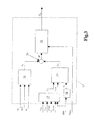
- the electronic control unit 12 of which only those components essential for comprehension of the present invention are shown, comprises an estimation module 13 which receives as input a series of engine magnitudes and operating parameters, and is adapted to generate as output, as a function of the latter, a signal indicating the estimated temperature T GS of the glow plug 11.
- the operating parameters are supplied to the electronic control unit 12 by a series of known sensors and/or transducers and/or measurement devices installed at various appropriate points of the engine.
- the electronic control unit 12 further comprises, a summing circuit 14 which receives as input a signal indicating the estimated temperature T GS and a signal indicating an objective temperature T GO corresponding to the temperature that needs to be reached by the glow plug 11, and supplies as output an error signal e T showing the difference between the objective temperature T GO to be reached and the estimated temperature T GS .
- a summing circuit 14 which receives as input a signal indicating the estimated temperature T GS and a signal indicating an objective temperature T GO corresponding to the temperature that needs to be reached by the glow plug 11, and supplies as output an error signal e T showing the difference between the objective temperature T GO to be reached and the estimated temperature T GS .
- the electronic control unit 12 further comprises a control module 15 which receives as input the error signal e T and generates, as a function of the latter, a control signal S COM which drives the glow plug 11.
- the control module 15 preferably generates the control signal S COM by a pulse width modulation PWM.
- the control signal S COM comprises a series of pulses characterised by a voltage value V a and by a specific duty cycle whose value is shown below by DCY.
- the control module 13 is adapted appropriately to modulate the duty cycle DCY and/or the voltage value V a of the control signal S COM to be supplied to the glow plug 11 as a function of the error signal e T so as to supply thereto a specific electrical power such that a corresponding thermal power can be generated by means of this plug 11.
- the estimation module 13 comprises a block 16 which receives as input a signal correlated with the voltage V a of the control signal S COM , a signal indicating the duty cycle DCY of the control signal S COM generated by the control module 15 and a signal indicating the electrical resistance R G of the glow plug 11.
- the block 16 is adapted to process the parameters V a , DCY and R G so as to provide as output a signal indicating the thermal power P TG generated by the glow plug 11 when the latter is supplied with the control signal S COM .
- the estimation module 13 further comprises a block 17 which is adapted to calculate the mean temperature T COMB in the combustion chamber 9 and a block 18 adapted to calculate a heat exchange coefficient hS.
- the block 17 receives as input a signal indicating the temperature T AIR of the intake air, a signal indicating the temperature T H2O of the cooling fluid, a signal indicating a parameter LOAD corresponding to the load measured in the engine 1, a signal indicating the number of engine revolutions RPM and a signal indicating the operating state of the engine S STATE .
- the signal indicating the operating state of the engine S STATE comprises, alternatively, a first operating state corresponding to a condition in which the engine is caused to rotate by the combustion process, or a second state corresponding to a condition in which the engine is stationary, or a third state corresponding to a condition in which the engine is caused to rotate in the absence of a combustion process.
- the first state may correspond, for instance, to the condition in which the engine is driven in rotation by the combustion process and has achieved a number of revolutions greater than a predetermined minimum value (for instance 780 RPM)
- the second operating state of the engine may correspond to a condition of non-combustion in which the engine is driven in rotation by an electrical starter device (starter motor) at a speed of rotation of approximately 250 RPM
- the third state may correspond to the condition in which the engine is stationary and the ignition key is in a Key On state.
- the signal indicating the operating state of the engine S STATE may be generated by a supervision module (not shown) of known type which is able, instant by instant, to determine the operating condition of the engine, while the signal indicating the parameter LOAD may be generated by a sensor mounted on the engine to measure its load (as shown in Fig. 1), or may be directly estimated by a calculation module of the electronic control unit 12 (not shown).
- the block 17 determines the temperature T COMB of the combustion chamber 9 by means of a series of functions stored in a memory (not shown) of the electronic control unit 12, each of which is selected by the block 17 as a function of the engine operating state S STATE .
- a first table containing a number of numerical values defining a first estimation function F ST1 (RPM, LOAD) of the temperature T COMB is stored in the memory (not shown) and is associated with the first engine operating state, making it possible to estimate, for each combination of the speed values RPM and the load LOAD, a corresponding value of the temperature T COMB .
- a second table containing a plurality of numerical values defining a second estimation function F ST2 (T H2O ) of the temperature T COMB is further stored in the memory (not shown) and is associated with the second engine operating state, making it possible to estimate, for each value of the temperature of the cooling fluid T H2O , a corresponding value of the temperature T COMB , as well as a third table containing a plurality of numerical values defining a third estimation function F ST3 (T AIR ) of the temperature T COMB , which is associated with the third operating state of the engine, making it possible to estimate, for each value of the temperature of the intake air T AIR , a corresponding value of the temperature T COMB .
- the block 18 receives as input the signal indicating the number of revolutions RPM and calculates, by means of a heat exchange function H(RPM), the heat exchange coefficient hS of the combustion chamber 9.
- a fourth table containing a plurality of numerical values defining the heat exchange function H(RPM) is stored in the memory (not shown), making it possible to calculate a corresponding heat exchange coefficient hS for each value of the number of engine revolutions RPM.
- the estimation module 13 further comprises a block 19 which receives as input the signal indicating the heat exchange coefficient hS, the signal indicating the temperature T COMB and a signal indicating the temperature T GS of the glow plug 11.
- the temperature T GS may be stored from time to time in the memory (not shown) and that the block 19 receives as input the signal corresponding to the last value of the temperature T GS calculated by the estimation module 13 during the previous estimation. It will also be appreciated that during the initial setting of the electronic control unit 12, when the estimation module 13 is operating for the first time, it is possible to assign an appropriate predetermined value to the temperature T GS .
- the block 19 processes the parameters T GS , T COMB and hS in order to provide as output a signal indicating the thermal power P TS exchanged with the operating fluid in the combustion chamber 9.
- the estimation module 13 lastly comprises a block 21 which is adapted to receive as input the signal indicating the difference ⁇ P between the thermal power P TG generated and the thermal power P TS exchanged, and a signal indicating the thermal capacity C tGLOW of the glow plug 11, whose value is predetermined, and processes the latter in order to supply as output the signal indicating the estimated temperature T GS of the glow plug 11.
- the estimation module 13 of the electronic control unit 12 estimates, instant by instant, the temperature T GS on the basis of the different engine parameters discussed above and the state of operation of this engine (first, second or third state) and the control module 15 appropriately modulates the control signal (in particular the duty cycle DCY and/or the voltage V a ) to be supplied to the glow plug 11, as a function of the error signal e T indicating the difference between the objective temperature T GO to be reached by the glow plug 11 and the estimated temperature T GS .
- the control signal in particular the duty cycle DCY and/or the voltage V a
- the block 17 in particular identifies in the memory (not shown), on the basis of the operating state S STATE of the engine, the estimation function to be used to calculate the internal temperature T COMB .
- the block 17 calculates the internal temperature T COMB using the first estimation function F ST1 (RPM, LOAD) on the basis of the speed RPM, and the load LOAD of the engine; while, if the operating state corresponds to the second or third state, the block 17 calculates the internal temperature T COMB using the second and third estimation functions F ST2 (T H2O ), F ST3 (T AIR ) on the basis of the temperature of the fluid T H2O and the temperature of the air T AIR respectively.
- the block 19 receives as input the signals corresponding to the parameters T GS , T COMB and hS, processes them and supplies as output the thermal power P TS exchanged, and at the same time the block 16 processes the parameters Va, DCY and R G to provide as output the signal indicating the thermal power P TG generated.
- the engine 1 and the control method of the glow plug 11 described above have the advantage of ensuring a precise and stable control of the temperature of the glow plug in any operating condition of the engine, at the same time ensuring a major reduction of the preheating time of this plug during the ignition phase.
- the method described above implements a feedback control of the temperature, thereby improving engine performance both in the ignition phase and in normal working conditions.
- the engine and the control method of the heating device described above have the advantage that they are simple and economic to embody as they enable a direct closed loop control of the temperature of the heating device based on the engine magnitudes typically available, without needing to use a temperature sensor mounted directly on the heating device, which latter solution, in addition to being extremely complex to industrialise, would also entail very high costs. It will be appreciated that the engine and the control method of the heating device as described and illustrated may be modified and varied without thereby departing from the scope of the present invention as set out in the accompanying claims.
Landscapes
- Engineering & Computer Science (AREA)
- Chemical & Material Sciences (AREA)
- Combustion & Propulsion (AREA)
- Mechanical Engineering (AREA)
- General Engineering & Computer Science (AREA)
- Combined Controls Of Internal Combustion Engines (AREA)
- Combustion Methods Of Internal-Combustion Engines (AREA)
- Ignition Installations For Internal Combustion Engines (AREA)
- Output Control And Ontrol Of Special Type Engine (AREA)
- Air-Conditioning For Vehicles (AREA)
- Cylinder Crankcases Of Internal Combustion Engines (AREA)
Priority Applications (1)
| Application Number | Priority Date | Filing Date | Title |
|---|---|---|---|
| PL06113550T PL1719909T3 (pl) | 2005-05-06 | 2006-05-05 | Silnik spalinowy wewnętrznego spalania wyposażony w świecę żarową w komorze spalania i sposób sterowania świecą żarową |
Applications Claiming Priority (1)
| Application Number | Priority Date | Filing Date | Title |
|---|---|---|---|
| IT000326A ITBO20050326A1 (it) | 2005-05-06 | 2005-05-06 | Motore a combustione interna provvisto di un dispositivo riscaldante in una camera di combustione e metodo di controllo del dispositivo riscaldante |
Publications (2)
| Publication Number | Publication Date |
|---|---|
| EP1719909A1 true EP1719909A1 (fr) | 2006-11-08 |
| EP1719909B1 EP1719909B1 (fr) | 2008-07-30 |
Family
ID=35501062
Family Applications (1)
| Application Number | Title | Priority Date | Filing Date |
|---|---|---|---|
| EP06113550A Expired - Lifetime EP1719909B1 (fr) | 2005-05-06 | 2006-05-05 | Moteur à combustion interne avec bougie à incandescence dans le cylindre et procédé pour la faire fonctionner |
Country Status (10)
| Country | Link |
|---|---|
| US (1) | US7528346B2 (fr) |
| EP (1) | EP1719909B1 (fr) |
| CN (1) | CN1880747B (fr) |
| AT (1) | ATE403083T1 (fr) |
| BR (1) | BRPI0601576B1 (fr) |
| DE (1) | DE602006001977D1 (fr) |
| ES (1) | ES2309905T3 (fr) |
| IT (1) | ITBO20050326A1 (fr) |
| PL (1) | PL1719909T3 (fr) |
| PT (1) | PT1719909E (fr) |
Cited By (12)
| Publication number | Priority date | Publication date | Assignee | Title |
|---|---|---|---|---|
| WO2007031341A1 (fr) * | 2005-09-16 | 2007-03-22 | Beru Aktiengesellschaft | Procede de commande de bougies de prechauffage dans des moteurs diesel |
| WO2007033825A1 (fr) * | 2005-09-21 | 2007-03-29 | Beru Aktiengesellschaft | Procede de commande d'un groupe de bougies de prechauffage d'un moteur diesel |
| EP1852604A1 (fr) * | 2006-05-05 | 2007-11-07 | Beru Aktiengesellschaft | Procédé de fonctionnement de bougies dans des moteurs diesel |
| WO2009097920A1 (fr) * | 2008-02-04 | 2009-08-13 | Robert Bosch Gmbh | Procédé et dispositif permettant de déterminer la température de bougies-crayons de préchauffage dans un moteur à combustion interne |
| WO2010037439A1 (fr) * | 2008-10-02 | 2010-04-08 | Gm Global Technology Operations, Inc. | Procédé de commande d'une bougie de préchauffage d'un moteur à combustion d'un véhicule et dispositif de commande pour une bougie de préchauffage d'un moteur à combustion d'un véhicule |
| GB2472811A (en) * | 2009-08-19 | 2011-02-23 | Gm Global Tech Operations Inc | Glowplug power control with a differential equation that is nonlinear in the glowplug temperature |
| DE102007031613B4 (de) * | 2007-07-06 | 2011-04-21 | Beru Ag | Verfahren zum Betreiben von Glühkerzen in Dieselmotoren |
| WO2011095529A3 (fr) * | 2010-02-08 | 2011-10-13 | Robert Bosch Gmbh | Procédé et dispositif permettant de faire fonctionner une bougie de préchauffage dans un moteur à combustion interne d'une automobile |
| US8322920B2 (en) | 2009-11-12 | 2012-12-04 | Robert Bosch Gmbh | Method and device for ascertaining a temperature of a sheathed-element glow plug in an internal combustion engine |
| DE102007058697B4 (de) * | 2006-12-11 | 2013-09-12 | GM Global Technology Operations LLC (n. d. Ges. d. Staates Delaware) | Glühkerzenlern- und -regelsystem |
| EP2826981A4 (fr) * | 2012-03-14 | 2017-08-09 | Nissan Motor Co., Ltd | Dispositif de commande et procédé de commande de moteur diesel |
| EP3581788A1 (fr) * | 2018-06-13 | 2019-12-18 | RENAULT s.a.s. | Procédé et système d'estimation de la température des bougies de préchauffage d'un moteur à combustion interne |
Families Citing this family (11)
| Publication number | Priority date | Publication date | Assignee | Title |
|---|---|---|---|---|
| MX2007014035A (es) * | 2007-11-09 | 2009-05-11 | Calentadores De America S A De | Calentador de agua de respaldo con encendido ionizado y control de tempertura electronico, para calentadores solares del tipo termosifon. |
| DE102008008205A1 (de) * | 2008-02-07 | 2009-08-13 | Robert Bosch Gmbh | Metallische Glühstiftkerze mit Temperaturmessung |
| DE102009038098B4 (de) * | 2009-08-19 | 2011-07-07 | Beru AG, 71636 | Verfahren zum Betreiben einer Glühkerze bei laufendem Motor |
| DE102010011044B4 (de) * | 2010-03-11 | 2012-12-27 | Borgwarner Beru Systems Gmbh | Verfahren zum Regeln einer Glühkerze |
| JP5660612B2 (ja) * | 2011-01-12 | 2015-01-28 | ボッシュ株式会社 | グロープラグ先端温度推定方法及びグロープラグ駆動制御装置 |
| US9683536B2 (en) * | 2013-05-16 | 2017-06-20 | Ford Global Technologies, Llc | Enhanced glow plug control |
| DE102013225267B4 (de) * | 2013-12-09 | 2018-01-18 | Robert Bosch Gmbh | Glühkerze mit einem Glühelement und einem Brennraumdrucksensor |
| US9634513B2 (en) * | 2014-07-25 | 2017-04-25 | Sony Corporation | Methods and systems of a battery charging profile |
| US9657707B2 (en) * | 2015-04-14 | 2017-05-23 | Sheldon J. Demmons | Autonomous glow driver for radio controlled engines |
| CN111946525A (zh) * | 2020-07-29 | 2020-11-17 | 蔡梦圆 | 用于二冲程汽油发动机热火头的转速变压式供电器 |
| CN114810458A (zh) * | 2022-05-25 | 2022-07-29 | 重庆利迈科技有限公司 | 发动机的热面助燃系统 |
Citations (3)
| Publication number | Priority date | Publication date | Assignee | Title |
|---|---|---|---|---|
| WO1995006203A1 (fr) * | 1993-08-25 | 1995-03-02 | Ford Motor Company Limited | Mise sous tension d'elements chauffants electriques |
| EP1408233A2 (fr) * | 2002-10-09 | 2004-04-14 | Beru AG | Procédé et dispositif de commande du chauffage des bougies à incandescence d' un moteur Diesel |
| DE10318241A1 (de) * | 2003-04-23 | 2004-11-11 | Robert Bosch Gmbh | Verfahren und Vorrichtung zum Betreiben einer Brennkraftmaschine |
Family Cites Families (8)
| Publication number | Priority date | Publication date | Assignee | Title |
|---|---|---|---|---|
| US3539970A (en) * | 1968-11-29 | 1970-11-10 | Amp Inc | Cam arrangement for programming system |
| US3512221A (en) * | 1969-04-07 | 1970-05-19 | Southwire Co | Aluminum alloy wire |
| US4002882A (en) * | 1975-03-05 | 1977-01-11 | Mccutchen Charles W | Heating circuit |
| US4552102A (en) * | 1981-05-04 | 1985-11-12 | Egle Edward J | System for improving the starting of diesel engines in cold weather |
| JPH03117685A (ja) * | 1989-09-29 | 1991-05-20 | Isuzu Motors Ltd | エンジン予熱装置 |
| US6148258A (en) * | 1991-10-31 | 2000-11-14 | Nartron Corporation | Electrical starting system for diesel engines |
| CN2309434Y (zh) * | 1997-08-02 | 1999-03-03 | 王文惠 | 机动车启动预热器 |
| US6233942B1 (en) * | 1999-07-15 | 2001-05-22 | Thermaldyne Llc | Condensing turbine |
-
2005
- 2005-05-06 IT IT000326A patent/ITBO20050326A1/it unknown
-
2006
- 2006-05-05 PT PT06113550T patent/PT1719909E/pt unknown
- 2006-05-05 EP EP06113550A patent/EP1719909B1/fr not_active Expired - Lifetime
- 2006-05-05 BR BRPI0601576-0A patent/BRPI0601576B1/pt not_active IP Right Cessation
- 2006-05-05 DE DE602006001977T patent/DE602006001977D1/de not_active Expired - Lifetime
- 2006-05-05 US US11/418,458 patent/US7528346B2/en active Active
- 2006-05-05 AT AT06113550T patent/ATE403083T1/de not_active IP Right Cessation
- 2006-05-05 PL PL06113550T patent/PL1719909T3/pl unknown
- 2006-05-05 ES ES06113550T patent/ES2309905T3/es not_active Expired - Lifetime
- 2006-05-08 CN CN200610105537XA patent/CN1880747B/zh not_active Expired - Fee Related
Patent Citations (3)
| Publication number | Priority date | Publication date | Assignee | Title |
|---|---|---|---|---|
| WO1995006203A1 (fr) * | 1993-08-25 | 1995-03-02 | Ford Motor Company Limited | Mise sous tension d'elements chauffants electriques |
| EP1408233A2 (fr) * | 2002-10-09 | 2004-04-14 | Beru AG | Procédé et dispositif de commande du chauffage des bougies à incandescence d' un moteur Diesel |
| DE10318241A1 (de) * | 2003-04-23 | 2004-11-11 | Robert Bosch Gmbh | Verfahren und Vorrichtung zum Betreiben einer Brennkraftmaschine |
Cited By (20)
| Publication number | Priority date | Publication date | Assignee | Title |
|---|---|---|---|---|
| JP2009508050A (ja) * | 2005-09-16 | 2009-02-26 | ベルー アクチェンゲゼルシャフト | ジーゼルエンジンのグロープラグを制御する方法 |
| WO2007031341A1 (fr) * | 2005-09-16 | 2007-03-22 | Beru Aktiengesellschaft | Procede de commande de bougies de prechauffage dans des moteurs diesel |
| WO2007033825A1 (fr) * | 2005-09-21 | 2007-03-29 | Beru Aktiengesellschaft | Procede de commande d'un groupe de bougies de prechauffage d'un moteur diesel |
| EP1852604A1 (fr) * | 2006-05-05 | 2007-11-07 | Beru Aktiengesellschaft | Procédé de fonctionnement de bougies dans des moteurs diesel |
| DE102007058697B4 (de) * | 2006-12-11 | 2013-09-12 | GM Global Technology Operations LLC (n. d. Ges. d. Staates Delaware) | Glühkerzenlern- und -regelsystem |
| DE102007031613B4 (de) * | 2007-07-06 | 2011-04-21 | Beru Ag | Verfahren zum Betreiben von Glühkerzen in Dieselmotoren |
| WO2009097920A1 (fr) * | 2008-02-04 | 2009-08-13 | Robert Bosch Gmbh | Procédé et dispositif permettant de déterminer la température de bougies-crayons de préchauffage dans un moteur à combustion interne |
| GB2464128B (en) * | 2008-10-02 | 2013-07-31 | Gm Global Tech Operations Inc | Method for controlling a glow plug of a combustion machine of a vehicle and controller for a glow plug of combustion machine of a vehicle |
| WO2010037439A1 (fr) * | 2008-10-02 | 2010-04-08 | Gm Global Technology Operations, Inc. | Procédé de commande d'une bougie de préchauffage d'un moteur à combustion d'un véhicule et dispositif de commande pour une bougie de préchauffage d'un moteur à combustion d'un véhicule |
| GB2472811A (en) * | 2009-08-19 | 2011-02-23 | Gm Global Tech Operations Inc | Glowplug power control with a differential equation that is nonlinear in the glowplug temperature |
| US8701614B2 (en) | 2009-08-19 | 2014-04-22 | GM Global Technology Operations LLC | Glowplug temperature estimation method and device |
| RU2539216C2 (ru) * | 2009-08-19 | 2015-01-20 | Джи Эм Глоубал Текнолоджи Оперейшнз, Инк. | Способ и устройство для оценки температуры запальной свечи |
| GB2472811B (en) * | 2009-08-19 | 2017-03-01 | Gm Global Tech Operations Llc | Glowplug temperature estimation method and device |
| US8322920B2 (en) | 2009-11-12 | 2012-12-04 | Robert Bosch Gmbh | Method and device for ascertaining a temperature of a sheathed-element glow plug in an internal combustion engine |
| WO2011095529A3 (fr) * | 2010-02-08 | 2011-10-13 | Robert Bosch Gmbh | Procédé et dispositif permettant de faire fonctionner une bougie de préchauffage dans un moteur à combustion interne d'une automobile |
| EP2826981A4 (fr) * | 2012-03-14 | 2017-08-09 | Nissan Motor Co., Ltd | Dispositif de commande et procédé de commande de moteur diesel |
| US9890719B2 (en) | 2012-03-14 | 2018-02-13 | Nissan Motor Co., Ltd. | Control apparatus and control method for diesel engine |
| US10626810B2 (en) | 2012-03-14 | 2020-04-21 | Nissan Motor Co., Ltd. | Control apparatus and control method for diesel engine |
| EP3581788A1 (fr) * | 2018-06-13 | 2019-12-18 | RENAULT s.a.s. | Procédé et système d'estimation de la température des bougies de préchauffage d'un moteur à combustion interne |
| FR3082557A1 (fr) * | 2018-06-13 | 2019-12-20 | Renault S.A.S | Procede et systeme d'estimation de la temperature des bougies de prechauffage d'un moteur a combustion interne |
Also Published As
| Publication number | Publication date |
|---|---|
| BRPI0601576B1 (pt) | 2020-12-15 |
| US20060289425A1 (en) | 2006-12-28 |
| ITBO20050326A1 (it) | 2006-11-07 |
| PT1719909E (pt) | 2008-10-29 |
| BRPI0601576A (pt) | 2006-12-26 |
| ATE403083T1 (de) | 2008-08-15 |
| DE602006001977D1 (de) | 2008-09-11 |
| EP1719909B1 (fr) | 2008-07-30 |
| PL1719909T3 (pl) | 2009-01-30 |
| CN1880747A (zh) | 2006-12-20 |
| CN1880747B (zh) | 2010-05-12 |
| US7528346B2 (en) | 2009-05-05 |
| ES2309905T3 (es) | 2008-12-16 |
Similar Documents
| Publication | Publication Date | Title |
|---|---|---|
| EP1719909B1 (fr) | Moteur à combustion interne avec bougie à incandescence dans le cylindre et procédé pour la faire fonctionner | |
| RU2716943C2 (ru) | Способ для определения температуры отработавших газов (варианты) | |
| CN101994631B (zh) | 估计电热塞温度的方法和装置 | |
| US7409928B2 (en) | Method for designing an engine component temperature estimator | |
| US7472014B1 (en) | Fast active fuel management reactivation | |
| US8635006B2 (en) | Control systems and methods for estimating engine coolant heat loss | |
| US10087815B2 (en) | System and method for estimating a cylinder wall temperature and for controlling coolant flow through an engine based on the estimated cylinder wall temperature | |
| US7708127B2 (en) | Fluid model control of electro-viscous fan clutch | |
| US8014930B2 (en) | System and method for determining oxygen sensor heater resistance | |
| RU2631583C2 (ru) | СПОСОБ РЕГУЛИРОВАНИЯ ТЕМПЕРАТУРЫ ДВИГАТЕЛЯ (варианты) | |
| CN102192070A (zh) | 一种控制电热塞的方法 | |
| CN104421021A (zh) | 基于发动机机油黏度用于发动机控制的系统和方法 | |
| US7631625B2 (en) | Glow plug learn and control system | |
| KR20110030377A (ko) | 펄스폭변조에 의해서 자동차 내의 발열체를 작동하는 방법 | |
| US10260445B2 (en) | Method of controlling a fuel injection system during rail pressure sensor failure condition | |
| JP2006525462A (ja) | ファンの運転延長 | |
| SE521897C2 (sv) | Förfarande och anordning för styrning av en förbränningsmotor | |
| JP2005256642A (ja) | 内燃機関の冷却制御装置 | |
| JP5911193B2 (ja) | 内燃機関におけるグロープラグの温度を算定するための方法および装置 | |
| US7089736B2 (en) | Variable nozzle turbo (VNT) solenoid temperature estimator | |
| US6561015B1 (en) | Model-based method of estimating crankcase oil pressure in an internal combustion engine | |
| JP2012072669A (ja) | 内燃機関制御システム | |
| Iskandar et al. | Design and analysis of a cooling control system of a diesel engine, to reduce emissions and fuel consumption | |
| KR100692131B1 (ko) | 엔진의 아이들 회전수 제어장치 및 방법 | |
| CN106194394B (zh) | 用于确定发动机内部温度的方法 |
Legal Events
| Date | Code | Title | Description |
|---|---|---|---|
| PUAI | Public reference made under article 153(3) epc to a published international application that has entered the european phase |
Free format text: ORIGINAL CODE: 0009012 |
|
| AK | Designated contracting states |
Kind code of ref document: A1 Designated state(s): AT BE BG CH CY CZ DE DK EE ES FI FR GB GR HU IE IS IT LI LT LU LV MC NL PL PT RO SE SI SK TR |
|
| AX | Request for extension of the european patent |
Extension state: AL BA HR MK YU |
|
| 17P | Request for examination filed |
Effective date: 20070222 |
|
| AKX | Designation fees paid |
Designated state(s): AT BE BG CH CY CZ DE DK EE ES FI FR GB GR HU IE IS IT LI LT LU LV MC NL PL PT RO SE SI SK TR |
|
| GRAP | Despatch of communication of intention to grant a patent |
Free format text: ORIGINAL CODE: EPIDOSNIGR1 |
|
| GRAS | Grant fee paid |
Free format text: ORIGINAL CODE: EPIDOSNIGR3 |
|
| GRAA | (expected) grant |
Free format text: ORIGINAL CODE: 0009210 |
|
| AK | Designated contracting states |
Kind code of ref document: B1 Designated state(s): AT BE BG CH CY CZ DE DK EE ES FI FR GB GR HU IE IS IT LI LT LU LV MC NL PL PT RO SE SI SK TR |
|
| REG | Reference to a national code |
Ref country code: GB Ref legal event code: FG4D |
|
| REG | Reference to a national code |
Ref country code: CH Ref legal event code: EP |
|
| REF | Corresponds to: |
Ref document number: 602006001977 Country of ref document: DE Date of ref document: 20080911 Kind code of ref document: P |
|
| REG | Reference to a national code |
Ref country code: IE Ref legal event code: FG4D |
|
| REG | Reference to a national code |
Ref country code: SE Ref legal event code: TRGR |
|
| REG | Reference to a national code |
Ref country code: PT Ref legal event code: SC4A Free format text: AVAILABILITY OF NATIONAL TRANSLATION Effective date: 20081016 |
|
| REG | Reference to a national code |
Ref country code: ES Ref legal event code: FG2A Ref document number: 2309905 Country of ref document: ES Kind code of ref document: T3 |
|
| PG25 | Lapsed in a contracting state [announced via postgrant information from national office to epo] |
Ref country code: LT Free format text: LAPSE BECAUSE OF FAILURE TO SUBMIT A TRANSLATION OF THE DESCRIPTION OR TO PAY THE FEE WITHIN THE PRESCRIBED TIME-LIMIT Effective date: 20080730 Ref country code: NL Free format text: LAPSE BECAUSE OF FAILURE TO SUBMIT A TRANSLATION OF THE DESCRIPTION OR TO PAY THE FEE WITHIN THE PRESCRIBED TIME-LIMIT Effective date: 20080730 Ref country code: IS Free format text: LAPSE BECAUSE OF FAILURE TO SUBMIT A TRANSLATION OF THE DESCRIPTION OR TO PAY THE FEE WITHIN THE PRESCRIBED TIME-LIMIT Effective date: 20081130 |
|
| REG | Reference to a national code |
Ref country code: PL Ref legal event code: T3 |
|
| PG25 | Lapsed in a contracting state [announced via postgrant information from national office to epo] |
Ref country code: BG Free format text: LAPSE BECAUSE OF FAILURE TO SUBMIT A TRANSLATION OF THE DESCRIPTION OR TO PAY THE FEE WITHIN THE PRESCRIBED TIME-LIMIT Effective date: 20081030 Ref country code: SI Free format text: LAPSE BECAUSE OF FAILURE TO SUBMIT A TRANSLATION OF THE DESCRIPTION OR TO PAY THE FEE WITHIN THE PRESCRIBED TIME-LIMIT Effective date: 20080730 Ref country code: LV Free format text: LAPSE BECAUSE OF FAILURE TO SUBMIT A TRANSLATION OF THE DESCRIPTION OR TO PAY THE FEE WITHIN THE PRESCRIBED TIME-LIMIT Effective date: 20080730 Ref country code: AT Free format text: LAPSE BECAUSE OF FAILURE TO SUBMIT A TRANSLATION OF THE DESCRIPTION OR TO PAY THE FEE WITHIN THE PRESCRIBED TIME-LIMIT Effective date: 20080730 Ref country code: FI Free format text: LAPSE BECAUSE OF FAILURE TO SUBMIT A TRANSLATION OF THE DESCRIPTION OR TO PAY THE FEE WITHIN THE PRESCRIBED TIME-LIMIT Effective date: 20080730 |
|
| PG25 | Lapsed in a contracting state [announced via postgrant information from national office to epo] |
Ref country code: BE Free format text: LAPSE BECAUSE OF FAILURE TO SUBMIT A TRANSLATION OF THE DESCRIPTION OR TO PAY THE FEE WITHIN THE PRESCRIBED TIME-LIMIT Effective date: 20080730 |
|
| PG25 | Lapsed in a contracting state [announced via postgrant information from national office to epo] |
Ref country code: DK Free format text: LAPSE BECAUSE OF FAILURE TO SUBMIT A TRANSLATION OF THE DESCRIPTION OR TO PAY THE FEE WITHIN THE PRESCRIBED TIME-LIMIT Effective date: 20080730 Ref country code: EE Free format text: LAPSE BECAUSE OF FAILURE TO SUBMIT A TRANSLATION OF THE DESCRIPTION OR TO PAY THE FEE WITHIN THE PRESCRIBED TIME-LIMIT Effective date: 20080730 |
|
| PG25 | Lapsed in a contracting state [announced via postgrant information from national office to epo] |
Ref country code: SK Free format text: LAPSE BECAUSE OF FAILURE TO SUBMIT A TRANSLATION OF THE DESCRIPTION OR TO PAY THE FEE WITHIN THE PRESCRIBED TIME-LIMIT Effective date: 20080730 Ref country code: CZ Free format text: LAPSE BECAUSE OF FAILURE TO SUBMIT A TRANSLATION OF THE DESCRIPTION OR TO PAY THE FEE WITHIN THE PRESCRIBED TIME-LIMIT Effective date: 20080730 Ref country code: RO Free format text: LAPSE BECAUSE OF FAILURE TO SUBMIT A TRANSLATION OF THE DESCRIPTION OR TO PAY THE FEE WITHIN THE PRESCRIBED TIME-LIMIT Effective date: 20080730 |
|
| PLBE | No opposition filed within time limit |
Free format text: ORIGINAL CODE: 0009261 |
|
| STAA | Information on the status of an ep patent application or granted ep patent |
Free format text: STATUS: NO OPPOSITION FILED WITHIN TIME LIMIT |
|
| 26N | No opposition filed |
Effective date: 20090506 |
|
| PGFP | Annual fee paid to national office [announced via postgrant information from national office to epo] |
Ref country code: ES Payment date: 20090529 Year of fee payment: 4 |
|
| PG25 | Lapsed in a contracting state [announced via postgrant information from national office to epo] |
Ref country code: IT Free format text: LAPSE BECAUSE OF FAILURE TO SUBMIT A TRANSLATION OF THE DESCRIPTION OR TO PAY THE FEE WITHIN THE PRESCRIBED TIME-LIMIT Effective date: 20080730 |
|
| PGFP | Annual fee paid to national office [announced via postgrant information from national office to epo] |
Ref country code: PL Payment date: 20090519 Year of fee payment: 4 Ref country code: PT Payment date: 20090515 Year of fee payment: 4 Ref country code: SE Payment date: 20090525 Year of fee payment: 4 |
|
| PG25 | Lapsed in a contracting state [announced via postgrant information from national office to epo] |
Ref country code: MC Free format text: LAPSE BECAUSE OF NON-PAYMENT OF DUE FEES Effective date: 20090531 |
|
| REG | Reference to a national code |
Ref country code: IE Ref legal event code: MM4A |
|
| PG25 | Lapsed in a contracting state [announced via postgrant information from national office to epo] |
Ref country code: IE Free format text: LAPSE BECAUSE OF NON-PAYMENT OF DUE FEES Effective date: 20090505 |
|
| PG25 | Lapsed in a contracting state [announced via postgrant information from national office to epo] |
Ref country code: GR Free format text: LAPSE BECAUSE OF FAILURE TO SUBMIT A TRANSLATION OF THE DESCRIPTION OR TO PAY THE FEE WITHIN THE PRESCRIBED TIME-LIMIT Effective date: 20081031 |
|
| REG | Reference to a national code |
Ref country code: PT Ref legal event code: MM4A Free format text: LAPSE DUE TO NON-PAYMENT OF FEES Effective date: 20101105 |
|
| REG | Reference to a national code |
Ref country code: CH Ref legal event code: PL |
|
| GBPC | Gb: european patent ceased through non-payment of renewal fee |
Effective date: 20100505 |
|
| EUG | Se: european patent has lapsed | ||
| PG25 | Lapsed in a contracting state [announced via postgrant information from national office to epo] |
Ref country code: PT Free format text: LAPSE BECAUSE OF NON-PAYMENT OF DUE FEES Effective date: 20101105 Ref country code: LI Free format text: LAPSE BECAUSE OF NON-PAYMENT OF DUE FEES Effective date: 20100531 Ref country code: CH Free format text: LAPSE BECAUSE OF NON-PAYMENT OF DUE FEES Effective date: 20100531 |
|
| PG25 | Lapsed in a contracting state [announced via postgrant information from national office to epo] |
Ref country code: SE Free format text: LAPSE BECAUSE OF NON-PAYMENT OF DUE FEES Effective date: 20100506 |
|
| PG25 | Lapsed in a contracting state [announced via postgrant information from national office to epo] |
Ref country code: LU Free format text: LAPSE BECAUSE OF NON-PAYMENT OF DUE FEES Effective date: 20090505 |
|
| PG25 | Lapsed in a contracting state [announced via postgrant information from national office to epo] |
Ref country code: HU Free format text: LAPSE BECAUSE OF FAILURE TO SUBMIT A TRANSLATION OF THE DESCRIPTION OR TO PAY THE FEE WITHIN THE PRESCRIBED TIME-LIMIT Effective date: 20090131 |
|
| PG25 | Lapsed in a contracting state [announced via postgrant information from national office to epo] |
Ref country code: GB Free format text: LAPSE BECAUSE OF NON-PAYMENT OF DUE FEES Effective date: 20100505 |
|
| PG25 | Lapsed in a contracting state [announced via postgrant information from national office to epo] |
Ref country code: TR Free format text: LAPSE BECAUSE OF FAILURE TO SUBMIT A TRANSLATION OF THE DESCRIPTION OR TO PAY THE FEE WITHIN THE PRESCRIBED TIME-LIMIT Effective date: 20080730 |
|
| PG25 | Lapsed in a contracting state [announced via postgrant information from national office to epo] |
Ref country code: CY Free format text: LAPSE BECAUSE OF FAILURE TO SUBMIT A TRANSLATION OF THE DESCRIPTION OR TO PAY THE FEE WITHIN THE PRESCRIBED TIME-LIMIT Effective date: 20080730 |
|
| REG | Reference to a national code |
Ref country code: ES Ref legal event code: FD2A Effective date: 20111118 |
|
| PG25 | Lapsed in a contracting state [announced via postgrant information from national office to epo] |
Ref country code: ES Free format text: LAPSE BECAUSE OF NON-PAYMENT OF DUE FEES Effective date: 20100506 |
|
| PG25 | Lapsed in a contracting state [announced via postgrant information from national office to epo] |
Ref country code: PL Free format text: LAPSE BECAUSE OF NON-PAYMENT OF DUE FEES Effective date: 20100505 |
|
| REG | Reference to a national code |
Ref country code: PL Ref legal event code: LAPE |
|
| REG | Reference to a national code |
Ref country code: FR Ref legal event code: PLFP Year of fee payment: 11 |
|
| REG | Reference to a national code |
Ref country code: FR Ref legal event code: PLFP Year of fee payment: 12 |
|
| REG | Reference to a national code |
Ref country code: FR Ref legal event code: PLFP Year of fee payment: 13 |
|
| PGFP | Annual fee paid to national office [announced via postgrant information from national office to epo] |
Ref country code: FR Payment date: 20220421 Year of fee payment: 17 |
|
| PGFP | Annual fee paid to national office [announced via postgrant information from national office to epo] |
Ref country code: DE Payment date: 20230419 Year of fee payment: 18 |
|
| PG25 | Lapsed in a contracting state [announced via postgrant information from national office to epo] |
Ref country code: FR Free format text: LAPSE BECAUSE OF NON-PAYMENT OF DUE FEES Effective date: 20230531 |
|
| REG | Reference to a national code |
Ref country code: DE Ref legal event code: R119 Ref document number: 602006001977 Country of ref document: DE |
|
| PG25 | Lapsed in a contracting state [announced via postgrant information from national office to epo] |
Ref country code: DE Free format text: LAPSE BECAUSE OF NON-PAYMENT OF DUE FEES Effective date: 20241203 |