EP1852696A2 - Röntgenstrahlfluoreszenzanalysegerät mit Mitteln zur Herstellung gesenkten Drucks und Röntgenstrahlfluoreszenzmessverfahren mittels gesenkten Drucks - Google Patents
Röntgenstrahlfluoreszenzanalysegerät mit Mitteln zur Herstellung gesenkten Drucks und Röntgenstrahlfluoreszenzmessverfahren mittels gesenkten Drucks Download PDFInfo
- Publication number
- EP1852696A2 EP1852696A2 EP07107430A EP07107430A EP1852696A2 EP 1852696 A2 EP1852696 A2 EP 1852696A2 EP 07107430 A EP07107430 A EP 07107430A EP 07107430 A EP07107430 A EP 07107430A EP 1852696 A2 EP1852696 A2 EP 1852696A2
- Authority
- EP
- European Patent Office
- Prior art keywords
- chamber
- gaseous medium
- pressure
- ray fluorescence
- torr
- Prior art date
- Legal status (The legal status is an assumption and is not a legal conclusion. Google has not performed a legal analysis and makes no representation as to the accuracy of the status listed.)
- Granted
Links
Images


Classifications
-
- G—PHYSICS
- G01—MEASURING; TESTING
- G01N—INVESTIGATING OR ANALYSING MATERIALS BY DETERMINING THEIR CHEMICAL OR PHYSICAL PROPERTIES
- G01N23/00—Investigating or analysing materials by the use of wave or particle radiation, e.g. X-rays or neutrons, not covered by groups G01N3/00 – G01N17/00, G01N21/00 or G01N22/00
- G01N23/22—Investigating or analysing materials by the use of wave or particle radiation, e.g. X-rays or neutrons, not covered by groups G01N3/00 – G01N17/00, G01N21/00 or G01N22/00 by measuring secondary emission from the material
- G01N23/223—Investigating or analysing materials by the use of wave or particle radiation, e.g. X-rays or neutrons, not covered by groups G01N3/00 – G01N17/00, G01N21/00 or G01N22/00 by measuring secondary emission from the material by irradiating the sample with X-rays or gamma-rays and by measuring X-ray fluorescence
-
- G—PHYSICS
- G01—MEASURING; TESTING
- G01N—INVESTIGATING OR ANALYSING MATERIALS BY DETERMINING THEIR CHEMICAL OR PHYSICAL PROPERTIES
- G01N2223/00—Investigating materials by wave or particle radiation
- G01N2223/07—Investigating materials by wave or particle radiation secondary emission
- G01N2223/076—X-ray fluorescence
Definitions
- the invention relates in general to the technology of X-ray fluorescence (XRF) analyzer devices.
- XRF X-ray fluorescence
- the invention concerns the technology of enhancing measurements of X-ray fluorescence peaks at low energies in the order of only few kiloelectronvolts.
- X-ray fluorescence is a measurement and analysis method in which incident X-rays coming from an X-ray source are allowed to hit a sample, causing electrons in the inner shells of constituent atoms to achieve excited states. When these excited states relax, the sample material emits fluorescent radiation at characteristic energies. Measuring the intensity and spectral characteristics of the fluorescent radiation with a detector allows deducing various facts about the material composition of the sample.
- X-ray fluorescence analysis is commonly used for scrap sorting and other needs of metal industry, to quickly identify the composition of alloys. Problems may arise with light element constituents such as Mg, Si, Al, and others, because some of the characteristic X-ray fluorescence radiation of these elements comes at energies of only few keV (kiloelectronvolts). For example the K alpha line of Mg at 1.25 keV experiences heavy attenuation in air, so that in an analyzer device with an air gap of 0.9 cm between the sample and the detector something like 88% of the Mg-K radiation is attenuated before reaching the detector.
- a disadvantage of the prior art device is the additional clumsiness that the external pump arrangement introduces.
- the pump arrangement also draws a significant amount of electric energy, so that it needs a direct connection to an electric wall outlet. Therefore the apparatus is not well suited for field conditions. Additionally the apparatus is only applicable for analysing samples that have a smooth, solid outer surface, because otherwise it is impossible to seal the front end of the chamber tightly against the sample.
- the objectives of the invention are achieved by providing the analyzer apparatus with an integrated air pump, which is capable of significantly lowering the pressure in an airtight chamber located at the front end of the analyzer apparatus.
- An X-ray fluorescence analyzer is characterized by the features recited in the characterising part of the independent claim directed to an X-ray fluorescence analyzer.
- a measurement method according to the invention is characterized in that by the features recited in the characterising part of the independent claim directed to a measurement method.
- a very large pressure difference between a closed chamber emptied of air and its environment requires all wall structures of the chamber to be relatively thick in order to withstand the pressure that tries to crush the chamber.
- the window should be so thick in order to achieve the required mechanical strength that it would cause much more attenuation to soft X-rays than what would be saved by pumping air out of the chamber.
- an X-ray fluorescence analyzer one part of which is designed to come into close contact with a sample.
- This part of the analyzer apparatus is equipped with a controllable X-ray source and a radiation detector configured to detect fluorescent X-rays induced in the sample upon bombardment with incident X-rays from the X-ray source.
- Said part of the analyzer apparatus also comprises an essentially airtight chamber, a wall of which comprises a window, which is permeable to X-rays.
- the geometry of the chamber, the window and the radiation detector allows fluorescent X-rays from a sample outside the window to pass through the window and across a part of the chamber to hit the detector.
- a conduit leads from said chamber to a low pressure source, which is most advantageously a pump, although also other kinds of low pressure sources can be used.
- a low pressure source which is most advantageously a pump, although also other kinds of low pressure sources can be used.
- the low pressure source it is possible to controllably lower the pressure inside the chamber to a certain value that is low enough to significantly reduce attenuation of soft X-rays in the gaseous medium that fills the chamber, but still high enough not to cause excessive mechanical stress to the walls of the chamber, particularly the window.
- the transmittivity to X-rays of the gaseous medium in the chamber depends strongly on its density. If the original intensity of fluorescent X-rays is to be determined, it is mandatory to have some knowledge about said density. This knowledge is easy to obtain by equipping the chamber with sensors sensing pressure and temperature, and calculating the density of the gaseous medium from the state equation of gases.
- Fig. 1 illustrates schematically a front end of an X-ray fluorescence analyzer.
- the use of the conventional designation "front” only illustrates the fact that this part of the X-ray fluorescence analyzer will come close to a sample 101, and does not include any directional limitations.
- the structures of the X-ray fluorescence analyzer define a chamber 102, one limiting surface of which is a window 103 in that surface that is to be brought into the close vicinity of the sample 101.
- the radiation input of a detector 104 is located inside the chamber 102, so that suitably directed fluorescent radiation from the sample 101 may enter the chamber 102 through the window 103 and hit the detector 104.
- the radiation output of a controllable X-ray source 105 is located inside the chamber 102. Incident radiation from the X-ray source 105 is directed through the window 103 to the sample 101.
- the chamber 102 contains air under normal atmospheric pressure. As was noted in the description of prior art above, this would result in heavy attenuation of fluorescent radiation in the energy range of only few keV.
- a conduit 106 that leads to a low pressure source (not shown).
- An electrically controlled valve 107 can be used to open and close the conduit 106 according to need. Before commencing the X-ray fluorescence measurement, the valve 107 is opened and the low pressure source is allowed to draw air from the chamber 102, so that the pressure inside the chamber assumes a value lower than the atmospheric pressure.
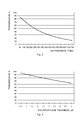
- Fig. 2 illustrates how the transmittivity of an air gap of 0.9 cm depends on photon energy, when air pressure is 190 torr and the measurement is made at room temperature.
- the pressure of 190 torr is one fourth of the nominal atmospheric pressure (760 torr).
- the left part of the transmittivity curve drops more steeply, while at lower pressures it slopes more and more gently. Changes are less significant towards the right-hand side of the curve, and at very low pressures the curve naturally begins to resemble a horizontal line at 100%.
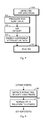
- Fig. 3 illustrates how the transmittivity of an 0.9 cm air gap changes for the K alpha energy of Mg as a function of air pressure.
- the window 103 is made of a material that is as transparent to X-rays as possible.
- Good window materials include, but are not limited to, polycarbonate, polypropylene and polyimide, and the thickness of the window foil is typically between 0.5 and 5 micrometers. Said polymer materials exhibit some elasticity, so that when pressure inside the chamber is lowered, the window bulges inwards. Assuming that the sample surface is flat, the bulging of the window creates a bubble-like space between the window and the sample surface. If there is no sealing mechanism at the sample side surface of the X-ray fluorescence analyzer, this bubble-like space is filled with air at atmospheric pressure, creating yet another attenuating layer.
- Fig. 4 illustrates the transmittivity of a polypropylene window foil for the K alpha energy of Mg as a function of foil thickness between 0.5 and 5 micrometers.
- a relatively thin foil is mechanically supported with a support grid that can be either an integral part of the window material or a separate layer next to the actual window foil.
- Advanced window configurations are known for example from a US patent application number 11/281638 , which is co-pending and assigned to the same applicant, and incorporated herein in its entirety by reference thereto.
- One way to determine an optimum value for the internal pressure of the chamber 102 is to plot the additional attenuation caused by the window foil and the "bulging bubble" as a function of chamber pressure for fluorescent energies in a range of interest, and to select a combination of window structure and internal pressure that together cause the smallest attenuation.
- Another aspect to consider in selecting the desired internal pressure value for the chamber is the nature of the low pressure source that should be used to draw air from the chamber. If the analyzer is or comprises a portable, handheld unit, it is very advantageous if the low pressure source is small and light enough to fit inside the device, like a small diaphragm pump for example. Small, lightweight electrically driven pumps typically have certain limitations concerning the maximum pressure difference that they can produce and maintain.
- a Diaphragm Pump 2003V manufactured by Rietschle Thomas Puchheim GmbH, Germany has overall dimensions in the order of 20 x 34 x 60 mm, draws a maximum current of 350 mA from a DC operating voltage between 4.5 and 9.0 V, weighs only 40 grams and is capable of maintaining a pressure difference of 750 mbar (approximately 570 torr) between its input and output.
- Other miniature-sized, electrically driven, air-drawing pumps exist too and could be used.
- Fig. 3 shows that even a small decrease in chamber pressure already enhances the transmission; for example, decreasing chamber pressure by 30% from 760 torr to about 500 torr will double the transmission from 12% to 24%.
- an upper limit for the concept "lowered pressure" in the chamber is only little less than the surrounding atmospheric pressure.
- a lower limit comes from the performance of the low pressure source used, as well as from the tensile strength of the window material. We believe that it is not practical to aim at lower pressure than approximately 10 torr.
- a pressure sensor 108 and a temperature sensor 109 that are configured to give information about the internal pressure and temperature of the chamber 102. From the temperature and pressure information it is straightforward to calculate the density of air inside the chamber using the well-known state equation of gases.
- Using pressure and temperature sensors inside the chamber like in fig. 1 is not the only possible way of detecting the density of air. For example, since in many cases the temperature inside the chamber is essentially the same as the temperature of the chamber walls, it may not be necessary to place a temperature sensor inside the chamber, if one exists close enough to it so that it gives the temperature of the solid structure that defines the chamber. Even pressure can be measured from outside the chamber, for example by using a sensitive strain gauge strip to measure how much some part of the chamber wall deforms under the forces caused by the pressure difference.
- Yet another possibility to measure the density of air inside the chamber is to let some known part of the radiation produced by the controllable X-ray source to traverse the chamber and hit a detector, so that by comparing the known intensity of incident radiation and the detected amount of radiation across the chamber it is possible to deduce the density of air therebetween.
- Fig. 5 illustrates a system level approach to an XRF analyzer according to an embodiment of the invention.
- the X-ray source 501 is selected so that the incident X-rays it produces will be useful in exciting the relatively low-energy states of light elements in a sample.
- the X-ray detector 502 is selected so that it can reliably detect also the relatively low-energy fluorescent radiation coming from such light elements.
- a high voltage source 503 is coupled to deliver the necessary high voltages at least to the X-ray source 501 and possibly also to the X-ray detector 502, if high voltages are needed there for biasing.
- a density indicator subsystem 504 is configured to produce an indication of the density of air inside a chamber 505, through which fluorescent X-rays will go on their way from the sample (not shown) to the X-ray detector 502. As was described above, there are numerous possibilities for implementing the density indicator subsystem 504, one of the most straightforward ways being the use of pressure and temperature sensors.
- the output signals of the X-ray detector 502 and the density indicator subsystem 504 are coupled to a processing electronics block 506, which is configured to implement signal processing functions such as amplification, pulse shaping, filtering and A/D conversion.
- controllable valve 507 and a low pressure source here a pump 508, configured to draw air from the chamber 505 through the valve 507.
- a control subsystem 509 is coupled to the valve 507 and the pump 508 and configured to control their operation (i.e. to open and close the valve 507 and to switch the pump 508 on and off).
- a controlling microprocessor 510 is configured to act as the central controlling entity of the XRF analyzer. It controls the operation of the high voltage source 503 and possibly receives feedback therefrom; it receives the measurement information from the processing electronics block 506 and tunes the signal processing operations if needed; and it gives the pressure control commands to the control subsystem 509 and receives feedback.
- the controlling microprocessor 510 operates by executing a program stored in a program memory 511 and uses a data memory 512 for storing and retrieving data.
- the controlling microprocessor 510 is also coupled to a user interface 513, which typically comprises keys and/or switches through which a user can give input commands, and a display and/or other sensory indicators, such as lights and buzzers, to give sensory feedback to the user.
- a data interface 514 is provided and coupled to the controlling microprocessor 510 so that the XRF analyzer may exchange data with other electronic devices.
- the functionalities that are described here to take place in a single controlling microprocessor 510 may, in a way well known as such, be distributed among a number of different parts or circuits of the XRF analyzer.
- a conventional power subsystem 515 is configured to feed operating power to all electrically driven parts of the XRF analyzer.
- the system level configuration of fig. 5 is applicable irrespective of whether the XRF analyzer is of a portable, hand-held type or of a benchtop type.
- portable devices small size and weight are important design drivers, and power consumption should be minimized because the power subsystem 515 relies on rechargeable batteries for wireless operation.
- benchtop devices size and weight are less of a concern, which may allow e.g. the use of more accurately controllable pumps and valves for producing the lowered pressure in the chamber 505.
- Fig. 6 illustrates an exemplary measurement method according to an embodiment of the invention.
- a complete measurement may, but is not required to, contain multiple partial measurements at different pressures.
- the valve that closes the path between a chamber and a low pressure source is opened and at step 602 the pump that acts as a low pressure source is switched on.
- Steps 601 and 602 could take place in reverse order or they could be combined, if the pump is of a type that also acts as a valve.
- Pumping is continued in step 603 until a target pressure value is reached, after which the valve is closed and the pump is switched off at steps 604 and 605 (which could be combined or reversed).
- X-ray fluorescence measurement data is collected at step 606.
- This step thus includes all conventional steps such as irradiating the sample, detecting fluorescent X-rays and processing the detected signal. Basically it would be possible to measure simultaneously while the pump is on, but it is probable that the electric motor of the pump will produce interference signals, which might weaken the measurement accuracy. The pump will also vibrate when operating, which is another possible source of unwanted interference to the X-ray fluorescence measurement.
- Step 607 represents a check, whether other partial measurements remain to be made at different pressures. A positive finding at step 607 leads to step 601, while a negative finding ends the measurement process.
- Fig. 7 illustrates how a process of analysing the X-ray fluorescence measurement data, collected in a method that involves using lowered air pressure between the sample and the detector, preferably includes the steps necessary to derive the air density 702 from the output data 701 of the density indicator subsystem, to map the derived air density to a characteristic attenuation 703 at each measured fluorescent energy range, and to scale the measured fluorescent spectrum 704 accordingly at step 705 to remove the energy-dependent effect of attenuation in air. It is relatively straightforward to accomplish the scaling steps by storing into memory a mathematical formula that links a given air density value to the corresponding transmission percentage at each energy, or by storing into memory an appropriate number of previously calculated energy- and density-dependent transmission percentage values in the form of look-up tables.
- a principle of normalizing certain measured intensity values can be applied in order to reduce the uncertainty caused by attenuation in air.
- air that is causing attenuation we may consider the lowered-pressure air that is left in the chamber, and/or the air that will remain between the sample and the input window.
- the last-mentioned is the more difficult to control otherwise, because it may result from effects that are difficult to anticipate, such as the sample surface being uneven or the formation of the bubble-like air-filled space when the window bulges inwards.
- the K alpha lines of light elements like Mg, Si and Al are so close to each other that a layer of air with unknown density and/or layer thickness will cause essentially an identical percentage of attenuation to all of them.
- a detector will detect intensities (100-p)A, (100-p)B, and (100-p)C, respectively.
- intensities (100-p)A, (100-p)B, and (100-p)C respectively.
- One such expression is the sum of said three detected intensities, so that as an processed intensity value for Mg one would use the ratio A / (A+B+C), from which ratio the common factor (100-p) has been cancelled out.
- FIG. 8 represents schematically steps of a data processing method in which the acquisition of detected intensity values at step 801 is followed by normalization at step 802.
- cryogenic cooling unit as a low pressure source, so that instead of (or in addition to) drawing air from the inside of the chamber to the outside, some part(s) of the walls of the chamber would be cooled enough to cause some of the component gases to solidify onto the cooled spot.
- pumping air from the chamber is much simpler to do in practice.
Landscapes
- Physics & Mathematics (AREA)
- Health & Medical Sciences (AREA)
- Life Sciences & Earth Sciences (AREA)
- Chemical & Material Sciences (AREA)
- Analytical Chemistry (AREA)
- Biochemistry (AREA)
- General Health & Medical Sciences (AREA)
- General Physics & Mathematics (AREA)
- Immunology (AREA)
- Pathology (AREA)
- Analysing Materials By The Use Of Radiation (AREA)
Applications Claiming Priority (1)
| Application Number | Priority Date | Filing Date | Title |
|---|---|---|---|
| US11/429,172 US7409037B2 (en) | 2006-05-05 | 2006-05-05 | X-ray fluorescence analyzer having means for producing lowered pressure, and an X-ray fluorescence measurement method using lowered pressure |
Publications (3)
| Publication Number | Publication Date |
|---|---|
| EP1852696A2 true EP1852696A2 (de) | 2007-11-07 |
| EP1852696A3 EP1852696A3 (de) | 2010-12-15 |
| EP1852696B1 EP1852696B1 (de) | 2013-01-16 |
Family
ID=38434654
Family Applications (1)
| Application Number | Title | Priority Date | Filing Date |
|---|---|---|---|
| EP07107430A Active EP1852696B1 (de) | 2006-05-05 | 2007-05-03 | Röntgenstrahlfluoreszenzanalysegerät mit Mitteln zur Herstellung gesenkten Drucks und Röntgenstrahlfluoreszenzmessverfahren mittels gesenkten Drucks |
Country Status (2)
| Country | Link |
|---|---|
| US (1) | US7409037B2 (de) |
| EP (1) | EP1852696B1 (de) |
Cited By (2)
| Publication number | Priority date | Publication date | Assignee | Title |
|---|---|---|---|---|
| EP2096431A1 (de) * | 2008-02-27 | 2009-09-02 | Oxford Instruments Analytical Oy | Tragbares Röntgenstrahlungsfluoreszenzanalysegerät |
| ITRM20130705A1 (it) * | 2013-12-20 | 2015-06-21 | Ilaria Carocci | Metodo e apparato per l'analisi di materiali mediante fluorescenza per raggi x a fascio aperto |
Families Citing this family (28)
| Publication number | Priority date | Publication date | Assignee | Title |
|---|---|---|---|---|
| US8064570B2 (en) * | 2006-12-20 | 2011-11-22 | Innov-X-Systems, Inc. | Hand-held XRF analyzer |
| US7916834B2 (en) * | 2007-02-12 | 2011-03-29 | Thermo Niton Analyzers Llc | Small spot X-ray fluorescence (XRF) analyzer |
| US20090086903A1 (en) * | 2007-09-28 | 2009-04-02 | Searete LLC, a limited liability corporation of | Selective elemental color providing for X-ray fluorescence visualization, imaging, or information providing |
| US7653173B2 (en) * | 2007-09-28 | 2010-01-26 | Searete Llc | Combining X-ray fluorescence visualizer, imager, or information provider |
| US7660385B2 (en) * | 2007-09-28 | 2010-02-09 | Searete Llc | Time of flight aspects for X-Ray fluorescence visualizer, imager, or information provider |
| US7664224B2 (en) * | 2007-09-28 | 2010-02-16 | Searete Llc | X-ray fluorescence visualizing, imaging, or information providing of chemicals, compounds, or biological materials |
| US7825376B2 (en) * | 2007-09-28 | 2010-11-02 | The Invention Science Fund I | Scintillator aspects for X-ray fluorescence visualizer, imager, or information provider |
| US8000438B2 (en) * | 2007-09-28 | 2011-08-16 | The Invention Science Fund I, Llc | Tool based X-ray fluorescence visualizing, imaging, or information providing |
| US20090086899A1 (en) * | 2007-09-28 | 2009-04-02 | Searete Llc, A Limited Liability Corporation Of The State Of Delaware | Repositioning X-ray fluorescence visualizer, imager, or information provider |
| US7773722B2 (en) * | 2007-09-28 | 2010-08-10 | The Invention Science Fund I, Llc | Personal transportable X-ray fluorescence visualizing, imaging, or information providing |
| US7724867B2 (en) * | 2007-09-28 | 2010-05-25 | Invention Science Fund I, Llc | Proximity-based X-Ray fluorescence visualizer, imager, or information provider |
| US8041005B2 (en) * | 2007-09-28 | 2011-10-18 | The Invention Science Fund I, Llc | X-ray fluorescence visualizer, imager, or information provider |
| US7738627B2 (en) * | 2007-09-28 | 2010-06-15 | The Invention Science Fund I, Llc | Geometric X-ray fluorescence visualizer, imager, or information provider |
| US7702066B2 (en) * | 2007-09-28 | 2010-04-20 | Searete Llc | Portable aspects for x-ray fluorescence visualizer, imager, or information provider |
| US20100080351A1 (en) * | 2008-09-26 | 2010-04-01 | i-Nalysis LLC | Handheld spectrometer |
| US20120236989A1 (en) * | 2011-03-16 | 2012-09-20 | Peter John Hardman | Portable XRF analyzer for low atomic number elements |
| CN104395983B (zh) * | 2012-04-20 | 2017-10-10 | 布鲁克Axs手持设备公司 | 用于保护辐射窗口的设备 |
| JP6082634B2 (ja) * | 2013-03-27 | 2017-02-15 | 株式会社日立ハイテクサイエンス | 蛍光x線分析装置 |
| US20140301530A1 (en) * | 2013-04-08 | 2014-10-09 | James L. Failla, JR. | Protective shield for x-ray fluorescence (xrf) system |
| US20140301531A1 (en) * | 2013-04-08 | 2014-10-09 | James L. Failla, JR. | Protective shield for x-ray fluorescence (xrf) system |
| US9594033B2 (en) | 2014-07-22 | 2017-03-14 | The Boeing Company | Visible X-ray indication and detection system for X-ray backscatter applications |
| DE102015221323B3 (de) * | 2015-10-30 | 2016-08-04 | Airbus Defence and Space GmbH | Verfahren zum Nachweis von Oberflächenverunreinigungen mittels Röntgenfluoreszenzanalyse |
| US10641718B2 (en) | 2016-07-29 | 2020-05-05 | Bruker Handheld Llc | X-ray fluorescence analyzer |
| US11592407B2 (en) | 2018-05-18 | 2023-02-28 | Enersoft Inc. | Systems, devices, and methods for x-ray fluorescence analysis of geological samples |
| JP7302504B2 (ja) * | 2020-02-27 | 2023-07-04 | 株式会社島津製作所 | 蛍光x線分析装置 |
| WO2022058912A1 (en) | 2020-09-16 | 2022-03-24 | Enersoft Inc. | Multiple-sensor analysis of geological samples |
| EP4083615B1 (de) * | 2021-04-26 | 2024-02-07 | Hitachi High-Tech Analytical Science Finland Oy | Xfr-analysatorinstrument |
| WO2022266779A1 (en) | 2021-06-25 | 2022-12-29 | Enersoft Inc. | Laser induced breakdown spectroscopy for geological analysis |
Family Cites Families (11)
| Publication number | Priority date | Publication date | Assignee | Title |
|---|---|---|---|---|
| JPH0762656B2 (ja) * | 1986-05-28 | 1995-07-05 | 株式会社島津製作所 | 螢光x線分析装置 |
| JP2959579B2 (ja) * | 1990-06-19 | 1999-10-06 | キヤノン株式会社 | X線露光装置 |
| US5407641A (en) * | 1990-10-25 | 1995-04-18 | Helmut Katschnig | Microwave apparatus, and container for use in a microwave apparatus |
| FI97647C (fi) * | 1994-11-14 | 1997-01-27 | Ima Engineering Ltd Oy | Menetelmä ja laitteisto alkuaineen pitoisuuden määrittämiseksi |
| EP0781992B1 (de) * | 1995-12-21 | 2006-06-07 | Horiba, Ltd. | Röntgenfluoreszenzanalysegerät |
| GB9613922D0 (en) * | 1996-07-03 | 1996-09-04 | Oxford Analytical Instr Ltd | X-ray fluorescence analysis |
| JP3921872B2 (ja) * | 1999-05-20 | 2007-05-30 | 株式会社島津製作所 | 蛍光x線分析用データ処理装置 |
| US6909707B2 (en) * | 2001-11-06 | 2005-06-21 | Motorola, Inc. | Method and apparatus for pseudo-random noise offset reuse in a multi-sector CDMA system |
| ATE476088T1 (de) * | 2001-12-04 | 2010-08-15 | X Ray Optical Sys Inc | Röntgenquelle mit verbesserter strahlstabilität und ihre anwendung in der analyse von strömenden flüssigkeiten |
| US6909770B2 (en) | 2001-12-05 | 2005-06-21 | The United States Of America As Represented By The United States National Aeronautics And Space Administration | Methods for identification and verification using vacuum XRF system |
| US6922455B2 (en) * | 2002-01-28 | 2005-07-26 | Starfire Industries Management, Inc. | Gas-target neutron generation and applications |
-
2006
- 2006-05-05 US US11/429,172 patent/US7409037B2/en not_active Expired - Lifetime
-
2007
- 2007-05-03 EP EP07107430A patent/EP1852696B1/de active Active
Cited By (2)
| Publication number | Priority date | Publication date | Assignee | Title |
|---|---|---|---|---|
| EP2096431A1 (de) * | 2008-02-27 | 2009-09-02 | Oxford Instruments Analytical Oy | Tragbares Röntgenstrahlungsfluoreszenzanalysegerät |
| ITRM20130705A1 (it) * | 2013-12-20 | 2015-06-21 | Ilaria Carocci | Metodo e apparato per l'analisi di materiali mediante fluorescenza per raggi x a fascio aperto |
Also Published As
| Publication number | Publication date |
|---|---|
| EP1852696A3 (de) | 2010-12-15 |
| US7409037B2 (en) | 2008-08-05 |
| EP1852696B1 (de) | 2013-01-16 |
| US20070269003A1 (en) | 2007-11-22 |
Similar Documents
| Publication | Publication Date | Title |
|---|---|---|
| EP1852696B1 (de) | Röntgenstrahlfluoreszenzanalysegerät mit Mitteln zur Herstellung gesenkten Drucks und Röntgenstrahlfluoreszenzmessverfahren mittels gesenkten Drucks | |
| EP2085772B1 (de) | Vorrichtung und Verfahren zur Röntgenstrahlfluoreszenz-Analyse einer Mineralprobe | |
| EP3076873B1 (de) | System zur erzeugung spektraler projektionsdaten | |
| JP5135602B2 (ja) | X線管及びx線分析装置 | |
| US7624623B2 (en) | Instrument and method for detecting leaks in hermetically sealed packaging | |
| EP2096431A1 (de) | Tragbares Röntgenstrahlungsfluoreszenzanalysegerät | |
| US9594037B2 (en) | Analyzing apparatus and calibration method | |
| AU6441600A (en) | X-ray fluorescence sensor for measurement of metal sheet thickness | |
| EP2197019A3 (de) | Röntgendetektor für Elektronenmikroskope | |
| CN109997031B (zh) | 用于检测材料的x射线荧光系统和方法以及控制系统 | |
| JP2008268076A (ja) | 非破壊識別方法及び非破壊識別装置 | |
| US8064570B2 (en) | Hand-held XRF analyzer | |
| CN115343321A (zh) | 用于x射线荧光分析的设备和方法 | |
| Szalóki et al. | A novel confocal XRF-Raman spectrometer and FPM model for analysis of solid objects and liquid substances | |
| EP2860552A1 (de) | Strahlendosimeter und verfahren zur strahlendosisberechnung | |
| EP2116842B1 (de) | Röntgenfluoreszenzanalysator mit gasgefüllter Kammer | |
| US20080008293A1 (en) | Energy dispersion type radiation detecting system and method of measuring content of object element | |
| US20120321038A1 (en) | X-ray tube and x-ray fluorescence analyser utilizing selective excitation radiation | |
| Heimann et al. | Laser power meters as an X-ray power diagnostic for LCLS-II | |
| JP3981976B2 (ja) | X線分析方法 | |
| JP2006329944A (ja) | 蛍光x線分析装置 | |
| EP4083615B1 (de) | Xfr-analysatorinstrument | |
| CN120129831A (zh) | 荧光x射线分析方法、分析程序以及荧光x射线分析装置 | |
| TW201138556A (en) | Flat output response transmission x-ray tube | |
| JP2019056651A (ja) | ガラスユニット内の気体成分の成分分析方法と、気体採取用治具 |
Legal Events
| Date | Code | Title | Description |
|---|---|---|---|
| PUAI | Public reference made under article 153(3) epc to a published international application that has entered the european phase |
Free format text: ORIGINAL CODE: 0009012 |
|
| AK | Designated contracting states |
Kind code of ref document: A2 Designated state(s): AT BE BG CH CY CZ DE DK EE ES FI FR GB GR HU IE IS IT LI LT LU LV MC MT NL PL PT RO SE SI SK TR |
|
| AX | Request for extension of the european patent |
Extension state: AL BA HR MK YU |
|
| PUAL | Search report despatched |
Free format text: ORIGINAL CODE: 0009013 |
|
| AK | Designated contracting states |
Kind code of ref document: A3 Designated state(s): AT BE BG CH CY CZ DE DK EE ES FI FR GB GR HU IE IS IT LI LT LU LV MC MT NL PL PT RO SE SI SK TR |
|
| AX | Request for extension of the european patent |
Extension state: AL BA HR MK RS |
|
| 17P | Request for examination filed |
Effective date: 20110412 |
|
| 17Q | First examination report despatched |
Effective date: 20110524 |
|
| AKX | Designation fees paid |
Designated state(s): AT BE BG CH CY CZ DE DK EE ES FI FR GB GR HU IE IS IT LI LT LU LV MC MT NL PL PT RO SE SI SK TR |
|
| GRAP | Despatch of communication of intention to grant a patent |
Free format text: ORIGINAL CODE: EPIDOSNIGR1 |
|
| GRAP | Despatch of communication of intention to grant a patent |
Free format text: ORIGINAL CODE: EPIDOSNIGR1 |
|
| GRAS | Grant fee paid |
Free format text: ORIGINAL CODE: EPIDOSNIGR3 |
|
| GRAA | (expected) grant |
Free format text: ORIGINAL CODE: 0009210 |
|
| AK | Designated contracting states |
Kind code of ref document: B1 Designated state(s): AT BE BG CH CY CZ DE DK EE ES FI FR GB GR HU IE IS IT LI LT LU LV MC MT NL PL PT RO SE SI SK TR |
|
| REG | Reference to a national code |
Ref country code: GB Ref legal event code: FG4D Ref country code: DE Ref legal event code: R081 Ref document number: 602007028045 Country of ref document: DE Owner name: OXFORD INSTRUMENTS INDUSTRIAL ANALYSIS OY, FI Free format text: FORMER OWNER: OXFORD INSTRUMENTS ANALYTICAL OY, ESPOO, FI Ref country code: DE Ref legal event code: R081 Ref document number: 602007028045 Country of ref document: DE Owner name: HITACHI HIGH-TECH ANALYTICAL SCIENCE FINLAND O, FI Free format text: FORMER OWNER: OXFORD INSTRUMENTS ANALYTICAL OY, ESPOO, FI |
|
| REG | Reference to a national code |
Ref country code: CH Ref legal event code: EP |
|
| REG | Reference to a national code |
Ref country code: IE Ref legal event code: FG4D |
|
| REG | Reference to a national code |
Ref country code: AT Ref legal event code: REF Ref document number: 594128 Country of ref document: AT Kind code of ref document: T Effective date: 20130215 Ref country code: CH Ref legal event code: EP |
|
| REG | Reference to a national code |
Ref country code: DE Ref legal event code: R096 Ref document number: 602007028045 Country of ref document: DE Effective date: 20130314 |
|
| REG | Reference to a national code |
Ref country code: AT Ref legal event code: MK05 Ref document number: 594128 Country of ref document: AT Kind code of ref document: T Effective date: 20130116 |
|
| REG | Reference to a national code |
Ref country code: NL Ref legal event code: VDEP Effective date: 20130116 |
|
| REG | Reference to a national code |
Ref country code: LT Ref legal event code: MG4D |
|
| PG25 | Lapsed in a contracting state [announced via postgrant information from national office to epo] |
Ref country code: BG Free format text: LAPSE BECAUSE OF FAILURE TO SUBMIT A TRANSLATION OF THE DESCRIPTION OR TO PAY THE FEE WITHIN THE PRESCRIBED TIME-LIMIT Effective date: 20130416 Ref country code: AT Free format text: LAPSE BECAUSE OF FAILURE TO SUBMIT A TRANSLATION OF THE DESCRIPTION OR TO PAY THE FEE WITHIN THE PRESCRIBED TIME-LIMIT Effective date: 20130116 Ref country code: SE Free format text: LAPSE BECAUSE OF FAILURE TO SUBMIT A TRANSLATION OF THE DESCRIPTION OR TO PAY THE FEE WITHIN THE PRESCRIBED TIME-LIMIT Effective date: 20130116 Ref country code: BE Free format text: LAPSE BECAUSE OF FAILURE TO SUBMIT A TRANSLATION OF THE DESCRIPTION OR TO PAY THE FEE WITHIN THE PRESCRIBED TIME-LIMIT Effective date: 20130116 Ref country code: ES Free format text: LAPSE BECAUSE OF FAILURE TO SUBMIT A TRANSLATION OF THE DESCRIPTION OR TO PAY THE FEE WITHIN THE PRESCRIBED TIME-LIMIT Effective date: 20130427 Ref country code: IS Free format text: LAPSE BECAUSE OF FAILURE TO SUBMIT A TRANSLATION OF THE DESCRIPTION OR TO PAY THE FEE WITHIN THE PRESCRIBED TIME-LIMIT Effective date: 20130516 Ref country code: LT Free format text: LAPSE BECAUSE OF FAILURE TO SUBMIT A TRANSLATION OF THE DESCRIPTION OR TO PAY THE FEE WITHIN THE PRESCRIBED TIME-LIMIT Effective date: 20130116 |
|
| PG25 | Lapsed in a contracting state [announced via postgrant information from national office to epo] |
Ref country code: SI Free format text: LAPSE BECAUSE OF FAILURE TO SUBMIT A TRANSLATION OF THE DESCRIPTION OR TO PAY THE FEE WITHIN THE PRESCRIBED TIME-LIMIT Effective date: 20130116 Ref country code: LV Free format text: LAPSE BECAUSE OF FAILURE TO SUBMIT A TRANSLATION OF THE DESCRIPTION OR TO PAY THE FEE WITHIN THE PRESCRIBED TIME-LIMIT Effective date: 20130116 Ref country code: NL Free format text: LAPSE BECAUSE OF FAILURE TO SUBMIT A TRANSLATION OF THE DESCRIPTION OR TO PAY THE FEE WITHIN THE PRESCRIBED TIME-LIMIT Effective date: 20130116 Ref country code: GR Free format text: LAPSE BECAUSE OF FAILURE TO SUBMIT A TRANSLATION OF THE DESCRIPTION OR TO PAY THE FEE WITHIN THE PRESCRIBED TIME-LIMIT Effective date: 20130417 Ref country code: PT Free format text: LAPSE BECAUSE OF FAILURE TO SUBMIT A TRANSLATION OF THE DESCRIPTION OR TO PAY THE FEE WITHIN THE PRESCRIBED TIME-LIMIT Effective date: 20130516 Ref country code: PL Free format text: LAPSE BECAUSE OF FAILURE TO SUBMIT A TRANSLATION OF THE DESCRIPTION OR TO PAY THE FEE WITHIN THE PRESCRIBED TIME-LIMIT Effective date: 20130116 Ref country code: FI Free format text: LAPSE BECAUSE OF FAILURE TO SUBMIT A TRANSLATION OF THE DESCRIPTION OR TO PAY THE FEE WITHIN THE PRESCRIBED TIME-LIMIT Effective date: 20130116 |
|
| PG25 | Lapsed in a contracting state [announced via postgrant information from national office to epo] |
Ref country code: EE Free format text: LAPSE BECAUSE OF FAILURE TO SUBMIT A TRANSLATION OF THE DESCRIPTION OR TO PAY THE FEE WITHIN THE PRESCRIBED TIME-LIMIT Effective date: 20130116 Ref country code: CZ Free format text: LAPSE BECAUSE OF FAILURE TO SUBMIT A TRANSLATION OF THE DESCRIPTION OR TO PAY THE FEE WITHIN THE PRESCRIBED TIME-LIMIT Effective date: 20130116 Ref country code: SK Free format text: LAPSE BECAUSE OF FAILURE TO SUBMIT A TRANSLATION OF THE DESCRIPTION OR TO PAY THE FEE WITHIN THE PRESCRIBED TIME-LIMIT Effective date: 20130116 Ref country code: RO Free format text: LAPSE BECAUSE OF FAILURE TO SUBMIT A TRANSLATION OF THE DESCRIPTION OR TO PAY THE FEE WITHIN THE PRESCRIBED TIME-LIMIT Effective date: 20130116 Ref country code: DK Free format text: LAPSE BECAUSE OF FAILURE TO SUBMIT A TRANSLATION OF THE DESCRIPTION OR TO PAY THE FEE WITHIN THE PRESCRIBED TIME-LIMIT Effective date: 20130116 |
|
| PLBE | No opposition filed within time limit |
Free format text: ORIGINAL CODE: 0009261 |
|
| STAA | Information on the status of an ep patent application or granted ep patent |
Free format text: STATUS: NO OPPOSITION FILED WITHIN TIME LIMIT |
|
| PG25 | Lapsed in a contracting state [announced via postgrant information from national office to epo] |
Ref country code: CY Free format text: LAPSE BECAUSE OF FAILURE TO SUBMIT A TRANSLATION OF THE DESCRIPTION OR TO PAY THE FEE WITHIN THE PRESCRIBED TIME-LIMIT Effective date: 20130116 |
|
| 26N | No opposition filed |
Effective date: 20131017 |
|
| PG25 | Lapsed in a contracting state [announced via postgrant information from national office to epo] |
Ref country code: IT Free format text: LAPSE BECAUSE OF FAILURE TO SUBMIT A TRANSLATION OF THE DESCRIPTION OR TO PAY THE FEE WITHIN THE PRESCRIBED TIME-LIMIT Effective date: 20130116 Ref country code: MC Free format text: LAPSE BECAUSE OF FAILURE TO SUBMIT A TRANSLATION OF THE DESCRIPTION OR TO PAY THE FEE WITHIN THE PRESCRIBED TIME-LIMIT Effective date: 20130116 |
|
| REG | Reference to a national code |
Ref country code: CH Ref legal event code: PL |
|
| PG25 | Lapsed in a contracting state [announced via postgrant information from national office to epo] |
Ref country code: LI Free format text: LAPSE BECAUSE OF NON-PAYMENT OF DUE FEES Effective date: 20130531 Ref country code: CH Free format text: LAPSE BECAUSE OF NON-PAYMENT OF DUE FEES Effective date: 20130531 |
|
| REG | Reference to a national code |
Ref country code: DE Ref legal event code: R097 Ref document number: 602007028045 Country of ref document: DE Effective date: 20131017 |
|
| REG | Reference to a national code |
Ref country code: IE Ref legal event code: MM4A |
|
| REG | Reference to a national code |
Ref country code: FR Ref legal event code: ST Effective date: 20140131 |
|
| PG25 | Lapsed in a contracting state [announced via postgrant information from national office to epo] |
Ref country code: IE Free format text: LAPSE BECAUSE OF NON-PAYMENT OF DUE FEES Effective date: 20130503 |
|
| PG25 | Lapsed in a contracting state [announced via postgrant information from national office to epo] |
Ref country code: FR Free format text: LAPSE BECAUSE OF NON-PAYMENT OF DUE FEES Effective date: 20130531 |
|
| PG25 | Lapsed in a contracting state [announced via postgrant information from national office to epo] |
Ref country code: MT Free format text: LAPSE BECAUSE OF FAILURE TO SUBMIT A TRANSLATION OF THE DESCRIPTION OR TO PAY THE FEE WITHIN THE PRESCRIBED TIME-LIMIT Effective date: 20130116 |
|
| PG25 | Lapsed in a contracting state [announced via postgrant information from national office to epo] |
Ref country code: TR Free format text: LAPSE BECAUSE OF FAILURE TO SUBMIT A TRANSLATION OF THE DESCRIPTION OR TO PAY THE FEE WITHIN THE PRESCRIBED TIME-LIMIT Effective date: 20130116 |
|
| PG25 | Lapsed in a contracting state [announced via postgrant information from national office to epo] |
Ref country code: LU Free format text: LAPSE BECAUSE OF NON-PAYMENT OF DUE FEES Effective date: 20130503 Ref country code: HU Free format text: LAPSE BECAUSE OF FAILURE TO SUBMIT A TRANSLATION OF THE DESCRIPTION OR TO PAY THE FEE WITHIN THE PRESCRIBED TIME-LIMIT; INVALID AB INITIO Effective date: 20070503 |
|
| REG | Reference to a national code |
Ref country code: DE Ref legal event code: R082 Ref document number: 602007028045 Country of ref document: DE Representative=s name: MUELLER-BORE & PARTNER PATENTANWAELTE PARTG MB, DE Ref country code: DE Ref legal event code: R081 Ref document number: 602007028045 Country of ref document: DE Owner name: OXFORD INSTRUMENTS INDUSTRIAL ANALYSIS OY, FI Free format text: FORMER OWNER: OXFORD INSTRUMENTS ANALYTICAL OY, ESPOO, FI Ref country code: DE Ref legal event code: R081 Ref document number: 602007028045 Country of ref document: DE Owner name: HITACHI HIGH-TECH ANALYTICAL SCIENCE FINLAND O, FI Free format text: FORMER OWNER: OXFORD INSTRUMENTS ANALYTICAL OY, ESPOO, FI |
|
| REG | Reference to a national code |
Ref country code: DE Ref legal event code: R082 Ref document number: 602007028045 Country of ref document: DE Representative=s name: MUELLER-BORE & PARTNER PATENTANWAELTE PARTG MB, DE Ref country code: DE Ref legal event code: R081 Ref document number: 602007028045 Country of ref document: DE Owner name: HITACHI HIGH-TECH ANALYTICAL SCIENCE FINLAND O, FI Free format text: FORMER OWNER: OXFORD INSTRUMENTS INDUSTRIAL ANALYSIS OY, ESPOO, FI |
|
| PGFP | Annual fee paid to national office [announced via postgrant information from national office to epo] |
Ref country code: DE Payment date: 20250520 Year of fee payment: 19 |
|
| PGFP | Annual fee paid to national office [announced via postgrant information from national office to epo] |
Ref country code: GB Payment date: 20250519 Year of fee payment: 19 |