EP1852885A1 - Elektrisches Relais - Google Patents
Elektrisches Relais Download PDFInfo
- Publication number
- EP1852885A1 EP1852885A1 EP07009039A EP07009039A EP1852885A1 EP 1852885 A1 EP1852885 A1 EP 1852885A1 EP 07009039 A EP07009039 A EP 07009039A EP 07009039 A EP07009039 A EP 07009039A EP 1852885 A1 EP1852885 A1 EP 1852885A1
- Authority
- EP
- European Patent Office
- Prior art keywords
- spring contact
- slider
- contact
- moveable
- base plane
- Prior art date
- Legal status (The legal status is an assumption and is not a legal conclusion. Google has not performed a legal analysis and makes no representation as to the accuracy of the status listed.)
- Granted
Links
Images





Classifications
-
- H—ELECTRICITY
- H01—ELECTRIC ELEMENTS
- H01H—ELECTRIC SWITCHES; RELAYS; SELECTORS; EMERGENCY PROTECTIVE DEVICES
- H01H3/00—Mechanisms for operating contacts
- H01H3/001—Means for preventing or breaking contact-welding
-
- H—ELECTRICITY
- H01—ELECTRIC ELEMENTS
- H01H—ELECTRIC SWITCHES; RELAYS; SELECTORS; EMERGENCY PROTECTIVE DEVICES
- H01H50/00—Details of electromagnetic relays
- H01H50/64—Driving arrangements between movable part of magnetic circuit and contact
- H01H50/641—Driving arrangements between movable part of magnetic circuit and contact intermediate part performing a rectilinear movement
- H01H50/642—Driving arrangements between movable part of magnetic circuit and contact intermediate part performing a rectilinear movement intermediate part being generally a slide plate, e.g. a card
-
- H—ELECTRICITY
- H01—ELECTRIC ELEMENTS
- H01H—ELECTRIC SWITCHES; RELAYS; SELECTORS; EMERGENCY PROTECTIVE DEVICES
- H01H50/00—Details of electromagnetic relays
- H01H50/54—Contact arrangements
- H01H50/56—Contact spring sets
- H01H50/58—Driving arrangements structurally associated therewith; Mounting of driving arrangements on armature
Definitions
- the invention relates to a relay with a base which defines a base plane, a monostable or bistable magnetic system arranged on the base and comprising an armature, a moveable spring contact and a fixed spring contact which are respectively arranged perpendicular or parallel to the base plane, the moveable spring contact being arranged between the fixed spring contact and a slider which can be moved approximately parallel or perpendicular to the base plane, and the moveable spring contact being actively connected to the armature via the slider acting on the moveable spring contact.
- a (monostable) relay of this type with a slider which is arranged parallel to the base plane and transmits the movement of the armature to a contact system of the relay, is known, for example, from EP 1 244 127 A2 .
- the armature engages with a recess in the slider via an armature projection, so the tightening or opening movement of the armature plate is converted directly into a horizontal back-and-forth movement of the slider.
- the slider is substantially in the form of a rectangular plate, the armature being arranged in the region of the one narrow side and the contact system being arranged in the region of the opposing narrow side.
- the contact system In a monostable relay, the contact system consists, in the simplest case, of a single pair of spring contacts, i.e. of a moveable spring contact, which is moved from the slider toward the fixed spring contact when the armature tightens.
- the slider In the unexcited state of the magnetic system, the slider is drawn, for example, by the restoring force of the armature spring - or, in a bistable relay, by the counter-excitation of the coil - into the rest position.
- the restoring force inherent to the moveable spring contact then causes it to become detached from the fixed spring contact and the moveable spring contact returns rapidly to its rest position.
- Bistable relays or magnetic systems comprising an H-shaped armature, such as are known, for example, from DE 197 15 261 C1 and DE 93 20 696 U1 , can - in contrast to generally known monostable relays or magnetic systems - alternate between two stable switching positions by reversing the polarity of the magnetic system.
- a magnetic system of this type provides force for both switching directions, so force is applied to the spring contacts of the relay not only on closing but also on opening. This is especially advantageous in relation to the tearing of welds occurring during the electrical service life of the relay.
- Fig. 1 shows an actuating slider 2 which can be moved horizontal to a base plane 1 defined by a base plate of a base 4 of the relay.
- the end of the moveable spring contact 3 that is remote from the base plane 1 is fixedly enclosed in a slotted recess 5 in the slider 2.
- the object of the invention is to develop a relay of the type mentioned at the outset in such a way that welds of the moveable spring contact to the fixed spring contact are torn on actuation of the relay.
- the slider there is integrated on the slider at least one contact opening element for opening welded contacts and with which the slider engages behind the moveable spring contact at a variable distance, on the side facing the fixed spring contact, there being formed, when the slider is positioned to close the fixed spring contact, an interval such that, on opening of the magnetic system, the contact opening element strikes the welded moveable spring contact just before the magnetic system is fully opened.
- the invention is based on the idea of having the weld torn by the restoring energy of the slider and the armature.
- the distance (clearance) between the contact opening element and an end face of the moveable spring contact that faces the fixed spring contact has to be sufficiently great to enable the slider/magnetic system initially to open almost fully, despite the weld, and only then to remain suspended from the moveable spring contact.
- the contacts are fastened in the base so as to stand perpendicular to the base plane, and that the contact opening element, configured on the slider which is movable parallel to the base plane, is in the form of a hook which engages from above via the end of the moveable spring contact that is remote from the base plane.
- the contact opening element is in the form of a hook which is guided through a recess in the moveable spring contact and engages behind a portion of the moveable spring contact that is located above the recess. It is in this case advantageous, especially with regard to the assembly of the relay, if the contact opening element is formed by two hooks which are respectively guided through a recess arranged laterally in the moveable spring contact.
- a recess which extends perpendicular to the base plane and encompasses the end of the moveable spring contact that is remote from the base plane, the contact opening element being formed by an edge of the recess that faces the fixed spring contact.
- the invention can also be used in the case of a relay in which the contacts are fastened in the base so as to be located parallel to the base plane.
- the contact opening element configured as a slider which can move perpendicular to the base plane, is in the form of a hook which is guided through a recess in the moveable spring contact and engages behind a portion of the free end of the moveable spring contact that is located in the environment of the recess.
- this embodiment can also be used in the case of relays, the armature of which does not have an armature return spring.
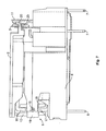
- Fig. 2 shows a first embodiment of a bistable relay according to the invention with an H-shaped armature 6.
- the relay shown in Fig. 2 has a base 4 which is made of an insulating material, is flat toward a connection side and has a base side that defines a base plane 1 from which electrical terminals 7 and 8 extend.
- the base 4 has a flat, trough-like recess for receiving a magnetic system, whereas the remaining part, comprising raised side walls 9 and optionally transverse walls 10, can, for example, be divided into individual contact carrier chambers.
- a relay contact system the configuration of which is very simple in the illustrated embodiment, consists of a moveable spring contact 3 and a fixed spring contact 11.
- the moveable spring contact 3 can be deflected horizontally and can be moved by a comb-like slider 2 arranged parallel to the base plane 1.
- the slider 2 At its end opposing the moveable spring contact 3 and the fixed spring contact 11, the slider 2 has an armature projection receiving recess 12 with which there engages an armature projection 14 which is integral with an armature plate 13 remote from a coil, cf. Fig. 3.
- Axle bearings 15 of the H-shaped armature 6 are mounted on both sides at bearing points of the base 4, allowing the H-shaped armature 6 to rotate about these bearing points, although the rotational movement is delimited by the striking of the free ends of yoke legs 16 and 17, cf. Fig. 7.
- the relay according to the invention can also be configured with substantially more complex systems, for example that described in DE 198 47 831 A1 .
- a rest contact (not shown), can also be provided, thus allowing, in contrast to the illustrated embodiments comprising a fixed spring contact relay, a changeover relay to be produced.
- the H-shaped armature 6 consists, cf. Fig. 7, of two armature plates 13 and 18 which are arranged substantially in parallel and are connected in a manner known per se by a permanent magnet located therebetween in such a way that the typical H-shaped cross-section is produced.
- the H-shaped armature 6 can be provided with a plastic material sheathing 19 which may be seen in Fig. 7, wherein the axle bearings 15 can also be formed integrally on both sides.
- the magnetic system comprising the H-shaped armature 6 therefore provides, in a manner known per se, force not only on closing of the relay but also in both switching directions.
- this also shows the slider 2 which is provided, in accordance with the invention, with a contact opening element 20, in the present case a hook which engages from above, via the end of the moveable spring contact 3 that is remote from the base plane 1.
- a contact opening element 20 in the present case a hook which engages from above, via the end of the moveable spring contact 3 that is remote from the base plane 1.
- the portion of the contact opening element 20 that runs parallel to the slider 2 extends relatively far toward the fixed spring contact 11 so, on opening of the relay, i.e. when the slider 2 moves toward the right, a certain distance (clearance) has first to be overcome before the contact spring element 20 strikes the moveable spring contact 3 and applies, as desired, a sudden, relatively intense pull to the moveable spring contact 3, leading to tearing of the weld. If there is no weld, the restoring force of the moveable spring contact 3 also causes it to move toward the right, so the contact opening element 20 will normally not strike the moveable spring contact 3.
- Fig. 2 shows an assembly state of the relay with the slider 2 which is provided with the contact opening element 20 according to the invention and is assembled so as to be laterally unfolded.
- a first lug 21 with which the slider 2 is guided and mounted in a recess 22 in the moveable spring contact 3.
- a second lug or shoulder which, in this embodiment, can rest on the moveable spring contact 3 only without bearings on account of the need for assembly in the assembled state.
- assembly of the relay with upwardly directed electrical terminals 7 and 8 could thus result in the slider 2 resting against the base 4, and this could, to a certain degree, result in abrasion which is undesirable from the point of view of the electrical service life of the relay.
- Fig. 3 shows a further embodiment containing two contact opening elements 20 which are each guided through the moveable spring contact 3 and upwardly engage behind the end face of the moveable spring contact 3 that faces the fixed spring contact 11.
- the slider 2 is, as may be seen, mounted on both sides in the moveable spring contact 3. This also facilitates, as illustrated in Figs. 4 and 5, an assembly in which the slider 2 is erected through approximately 90 degrees, the relay being arranged upright (i.e. with electrical terminals 7 and 8 directed downward), and is then folded downward, the two contact opening elements rotating into the recesses 22 in the moveable spring contact 3.
- Figs. 6 and 7 again show, in a slightly different view, the above-described embodiment.
- the relay is shown in the state with the welded contact zone 25, cf. Fig. 8.
- the slider 2 travels toward the right by means of the armature return spring and the mass of the slider 2 and the armature 6.
- the contact opening elements 20 apply a sudden pull to the moveable spring contact 3 which is intended to undo the weld.
- the opening force generated on counter-excitation of the coil at the end of the armature tightening movement causes substantially still more force to be applied in order to open the weld.
- a shoulder 23 which acts, on closing of the relay, on the side of the slider 2 in each case, on the moveable spring contact 3 and moves it toward the fixed spring contact 11.
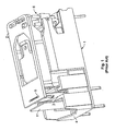
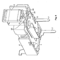
- Figs. 8 to 12 show, each in a differing view or illustration, an embodiment of the relay according to the invention in which the moveable spring contact 3 and the fixed spring contact 11 are fastened so as to be located in the base 4, whereas the slider 2 is accordingly arranged perpendicular to the base plane 1.
- Fig. 8 is a view obliquely onto the base side of the relay which is not yet fully fitted. At its lower end, facing the moveable spring contact 3, the slider 2, which can move perpendicular to the base plane 1, has a contact opening element 20 which is guided through a recess 22 located in the free end of the moveable spring contact 3, so the contact opening element 20 engages behind the side of the moveable spring contact 3 that faces the fixed spring contact 11.
- FIG. 9 is a view of the base side of the relay, showing even more clearly the arrangement with the moveable spring contact 3 and the fixed spring contact 11 fastened in the base 4 so as to be located parallel to the base plane 1.
- the free end of the moveable spring contact 3 has an arm 24 arranged so as to prevent the arm 24 from also being welded when the moveable spring contact 3 and the fixed spring contact 11 are welded in the region of the contact zone 25.
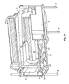
- Fig. 10 is a side view of a fully assembled relay.
- the functioning of the slider 2, provided in the lower region with the contact opening element 20 for the tearing of welded moveable spring contacts 3 and the fixed spring contact 11 and actively connected in the upper region to the armature 6, is substantially similar to that of the embodiments of the invention comprising a slider 2 arranged parallel to the base plane 1.
- the restoring force of the moveable spring contact 3, which in the closed switching state is pressed downward onto the fixed spring contact 11, causes it automatically also to move upward, so the contact therebetween is cancelled without the aid of the contact opening element 20.
- Figs. 8 to 10 uses a magnetic system, the armature 6 of which, cf. the sectional view of Figs. 11 and 12, does not have an armature return spring.
- the functioning of the armature return spring is replaced by the restoring force of the arm 24, cf. in particular Fig. 9, which automatically presses the slider 2 upward when the magnetic system is unexcited - regardless of whether or not the moveable spring contact 3 and the fixed spring contact 11 are welded - so the slider 2 presses the armature 6 back into its bearing position via a pivot point 26 arranged in the relay, cf. Fig. 12.
Landscapes
- Physics & Mathematics (AREA)
- Electromagnetism (AREA)
- Electromagnets (AREA)
- Switch Cases, Indication, And Locking (AREA)
- Relay Circuits (AREA)
- Arc-Extinguishing Devices That Are Switches (AREA)
Applications Claiming Priority (1)
| Application Number | Priority Date | Filing Date | Title |
|---|---|---|---|
| DE102006021203A DE102006021203B3 (de) | 2006-05-06 | 2006-05-06 | Elektrisches Relais |
Publications (2)
| Publication Number | Publication Date |
|---|---|
| EP1852885A1 true EP1852885A1 (de) | 2007-11-07 |
| EP1852885B1 EP1852885B1 (de) | 2009-04-15 |
Family
ID=38229887
Family Applications (1)
| Application Number | Title | Priority Date | Filing Date |
|---|---|---|---|
| EP07009039A Active EP1852885B1 (de) | 2006-05-06 | 2007-05-04 | Elektrisches Relais |
Country Status (7)
| Country | Link |
|---|---|
| US (2) | US20070257752A1 (de) |
| EP (1) | EP1852885B1 (de) |
| JP (1) | JP5004282B2 (de) |
| CN (1) | CN101106041B (de) |
| AT (1) | ATE429025T1 (de) |
| DE (2) | DE102006021203B3 (de) |
| ES (1) | ES2323437T3 (de) |
Cited By (5)
| Publication number | Priority date | Publication date | Assignee | Title |
|---|---|---|---|---|
| WO2009141315A1 (en) * | 2008-05-23 | 2009-11-26 | Tyco Electronics Austria Gmbh | Relay |
| EP2528080A1 (de) * | 2011-05-24 | 2012-11-28 | Panasonic Corporation | Elektromagnetisches Relais |
| CN104037026A (zh) * | 2014-06-30 | 2014-09-10 | 惠州亿纬锂能股份有限公司 | 一种磁保持继电器 |
| EP3021342A4 (de) * | 2013-07-12 | 2017-01-04 | Omron Corporation | Teil für kontaktstellenmechanismus und elektromagnetisches relais damit |
| EP4379766A1 (de) * | 2022-12-01 | 2024-06-05 | Solaredge Technologies Ltd. | Relaisumgehungsmechanismus |
Families Citing this family (9)
| Publication number | Priority date | Publication date | Assignee | Title |
|---|---|---|---|---|
| DE102006021203B3 (de) * | 2006-05-06 | 2008-01-17 | Tyco Electronics Austria Gmbh | Elektrisches Relais |
| CN102103942B (zh) | 2009-12-17 | 2013-06-05 | 厦门宏发电声股份有限公司 | 一种继电器的衔铁与推动机构之间的连接结构 |
| DE102010063229A1 (de) * | 2010-12-16 | 2012-06-21 | Tyco Electronics Austria Gmbh | Relais mit verbesserter Kontaktfeder |
| JP5917853B2 (ja) | 2011-08-11 | 2016-05-18 | 富士通コンポーネント株式会社 | スイッチ及びコネクタ |
| JP6341361B2 (ja) * | 2013-12-13 | 2018-06-13 | パナソニックIpマネジメント株式会社 | 電磁リレー |
| DE102014103247A1 (de) | 2014-03-11 | 2015-09-17 | Tyco Electronics Austria Gmbh | Elektromagnetisches Relais |
| CN104201058B (zh) * | 2014-09-12 | 2017-07-14 | 浙江凡华电子有限公司 | 电磁继电器 |
| EP3051557B1 (de) | 2015-01-30 | 2021-03-17 | Tyco Electronics Austria GmbH | Monolithischer Trägerkörper für ein Relais |
| JP7003788B2 (ja) * | 2018-03-27 | 2022-01-21 | オムロン株式会社 | リレー |
Citations (4)
| Publication number | Priority date | Publication date | Assignee | Title |
|---|---|---|---|---|
| EP0237610A2 (de) | 1986-03-21 | 1987-09-23 | Hengstler Bauelemente GmbH | Elektromagnetisches Relais |
| EP0579832A1 (de) * | 1991-04-09 | 1994-01-26 | Omron Corporation | Elektromagnetisches relais |
| DE10239284A1 (de) * | 2001-09-26 | 2003-04-17 | Tyco Electronics Amp Gmbh | Elektromagnetisches Relais mit nichtlinearem Kraft-Weg-Verhalten der Kontaktfeder und Kontaktfeder |
| EP1420429A1 (de) * | 2002-11-12 | 2004-05-19 | Omron Corporation | Elektromagnetisches Relais |
Family Cites Families (19)
| Publication number | Priority date | Publication date | Assignee | Title |
|---|---|---|---|---|
| DE3000681C2 (de) * | 1980-01-10 | 1983-08-11 | Eberle Anlagen KG, 8500 Nürnberg | Kontaktbetätigungsvorrichtung insbesondere für Relais |
| JPS6379037U (de) * | 1986-11-11 | 1988-05-25 | ||
| JP3383984B2 (ja) * | 1992-05-14 | 2003-03-10 | オムロン株式会社 | 電磁継電器 |
| US5289144A (en) * | 1992-08-21 | 1994-02-22 | Potter & Brumfield, Inc. | Electromagnetic relay and method for assembling the same |
| DE9320696U1 (de) | 1993-07-15 | 1994-11-24 | W. Gruner Gmbh Relaisfabrik, 78564 Wehingen | Relais zum Schalten hoher Stromstärken |
| JPH07254340A (ja) * | 1994-03-15 | 1995-10-03 | Omron Corp | 電磁継電器 |
| JPH103840A (ja) * | 1996-06-14 | 1998-01-06 | Omron Corp | 電磁継電器 |
| DE19715261C1 (de) * | 1997-04-12 | 1998-12-10 | Gruner Ag | Relais |
| DE19847831C2 (de) | 1998-10-16 | 2002-11-21 | Tyco Electronics Austria Gmbh | Sicherheitsrelais |
| EP1039284A1 (de) | 1999-03-24 | 2000-09-27 | ENVEC Mess- und Regeltechnik GmbH + Co. | Kapazitiver Drucksensor bzw. kapazitiver Differenzdrucksensoren |
| JP4085513B2 (ja) * | 1999-04-28 | 2008-05-14 | オムロン株式会社 | 電気機器の封止構造 |
| CN1221002C (zh) * | 1999-10-26 | 2005-09-28 | 松下电工株式会社 | 电磁继电器 |
| US20020024412A1 (en) * | 2000-08-23 | 2002-02-28 | Song Chuan Precision Co., Ltd. | Method of manufacturing a relay |
| DE60224894T2 (de) * | 2001-03-22 | 2009-01-29 | Tyco Electronics Austria Gmbh | Elektrisches Schaltelement |
| US6765463B2 (en) * | 2001-06-22 | 2004-07-20 | Tyco Electronics Austria, GmbH | Relay |
| JP4131160B2 (ja) * | 2002-11-08 | 2008-08-13 | オムロン株式会社 | 電磁継電器 |
| ES2382193T3 (es) * | 2004-01-28 | 2012-06-06 | Tyco Electronics Austria Gmbh | Relé de alta potencia con contacto resiliente normalmente abierto |
| JP4389652B2 (ja) * | 2004-04-30 | 2009-12-24 | オムロン株式会社 | 電磁継電器 |
| DE102006021203B3 (de) * | 2006-05-06 | 2008-01-17 | Tyco Electronics Austria Gmbh | Elektrisches Relais |
-
2006
- 2006-05-06 DE DE102006021203A patent/DE102006021203B3/de active Active
-
2007
- 2007-04-27 US US11/741,277 patent/US20070257752A1/en not_active Abandoned
- 2007-05-04 ES ES07009039T patent/ES2323437T3/es active Active
- 2007-05-04 AT AT07009039T patent/ATE429025T1/de not_active IP Right Cessation
- 2007-05-04 EP EP07009039A patent/EP1852885B1/de active Active
- 2007-05-04 DE DE602007000881T patent/DE602007000881D1/de active Active
- 2007-05-07 JP JP2007122374A patent/JP5004282B2/ja active Active
- 2007-05-08 CN CN2007101282560A patent/CN101106041B/zh active Active
-
2010
- 2010-04-13 US US12/759,458 patent/US7876184B2/en active Active
Patent Citations (4)
| Publication number | Priority date | Publication date | Assignee | Title |
|---|---|---|---|---|
| EP0237610A2 (de) | 1986-03-21 | 1987-09-23 | Hengstler Bauelemente GmbH | Elektromagnetisches Relais |
| EP0579832A1 (de) * | 1991-04-09 | 1994-01-26 | Omron Corporation | Elektromagnetisches relais |
| DE10239284A1 (de) * | 2001-09-26 | 2003-04-17 | Tyco Electronics Amp Gmbh | Elektromagnetisches Relais mit nichtlinearem Kraft-Weg-Verhalten der Kontaktfeder und Kontaktfeder |
| EP1420429A1 (de) * | 2002-11-12 | 2004-05-19 | Omron Corporation | Elektromagnetisches Relais |
Cited By (6)
| Publication number | Priority date | Publication date | Assignee | Title |
|---|---|---|---|---|
| WO2009141315A1 (en) * | 2008-05-23 | 2009-11-26 | Tyco Electronics Austria Gmbh | Relay |
| EP2528080A1 (de) * | 2011-05-24 | 2012-11-28 | Panasonic Corporation | Elektromagnetisches Relais |
| EP3021342A4 (de) * | 2013-07-12 | 2017-01-04 | Omron Corporation | Teil für kontaktstellenmechanismus und elektromagnetisches relais damit |
| CN104037026A (zh) * | 2014-06-30 | 2014-09-10 | 惠州亿纬锂能股份有限公司 | 一种磁保持继电器 |
| CN104037026B (zh) * | 2014-06-30 | 2016-05-04 | 惠州亿纬锂能股份有限公司 | 一种磁保持继电器 |
| EP4379766A1 (de) * | 2022-12-01 | 2024-06-05 | Solaredge Technologies Ltd. | Relaisumgehungsmechanismus |
Also Published As
| Publication number | Publication date |
|---|---|
| US7876184B2 (en) | 2011-01-25 |
| DE602007000881D1 (de) | 2009-05-28 |
| JP2007299758A (ja) | 2007-11-15 |
| ATE429025T1 (de) | 2009-05-15 |
| ES2323437T3 (es) | 2009-07-15 |
| DE102006021203B3 (de) | 2008-01-17 |
| US20100194502A1 (en) | 2010-08-05 |
| EP1852885B1 (de) | 2009-04-15 |
| CN101106041B (zh) | 2012-07-18 |
| JP5004282B2 (ja) | 2012-08-22 |
| US20070257752A1 (en) | 2007-11-08 |
| CN101106041A (zh) | 2008-01-16 |
Similar Documents
| Publication | Publication Date | Title |
|---|---|---|
| EP1852885B1 (de) | Elektrisches Relais | |
| US6661319B2 (en) | Bounce-reduced relay | |
| EP1840923B1 (de) | Magnetsystem mit H-förmigem Anker für ein Relais | |
| US6788176B2 (en) | Bounce-reduced relay | |
| EP2187420B1 (de) | Relais mit einer Schnapp-Feder | |
| EP2590194B1 (de) | Kontaktschaltermechanismus und elektromagnetisches Relais | |
| EP3846195B1 (de) | Gleichstromrelais | |
| US6831535B1 (en) | Bistable electromagnetic relay | |
| JP2025042609A (ja) | リレー | |
| EP1821327A3 (de) | Relais mit reduziertem Kriechstrom | |
| KR102219757B1 (ko) | 직접적인 아마추어 커플링을 포함하는 전기 스위칭 엘리먼트 | |
| EP1672660A2 (de) | Elektromagnetisches Relais | |
| WO2009141315A1 (en) | Relay | |
| CN1052332C (zh) | 电路断路器 | |
| CN213845169U (zh) | 磁保持继电器 | |
| EP0458302B1 (de) | Ferngesteuertes Relais | |
| EP0016196B1 (de) | Magnetische verriegelung für einen schalter des klappanker-typs | |
| US6046418A (en) | Drive system for switch, especially relay | |
| US11361925B2 (en) | Relay | |
| KR20250087652A (ko) | 릴레이 | |
| JPS6230775Y2 (de) | ||
| JPH04196019A (ja) | 接点開閉装置 | |
| JPH10214552A (ja) | 電磁リレー | |
| JPS6132322A (ja) | 電気接点装置 | |
| JPH06103876A (ja) | 接点開閉装置 |
Legal Events
| Date | Code | Title | Description |
|---|---|---|---|
| PUAI | Public reference made under article 153(3) epc to a published international application that has entered the european phase |
Free format text: ORIGINAL CODE: 0009012 |
|
| AK | Designated contracting states |
Kind code of ref document: A1 Designated state(s): AT BE BG CH CY CZ DE DK EE ES FI FR GB GR HU IE IS IT LI LT LU LV MC MT NL PL PT RO SE SI SK TR |
|
| AX | Request for extension of the european patent |
Extension state: AL BA HR MK YU |
|
| 17P | Request for examination filed |
Effective date: 20071124 |
|
| AKX | Designation fees paid |
Designated state(s): AT BE BG CH CY CZ DE DK EE ES FI FR GB GR HU IE IS IT LI LT LU LV MC MT NL PL PT RO SE SI SK TR |
|
| RIN1 | Information on inventor provided before grant (corrected) |
Inventor name: MIKL, RUDOLF Inventor name: LOY JOHANN Inventor name: STANGL, GERHARD |
|
| GRAP | Despatch of communication of intention to grant a patent |
Free format text: ORIGINAL CODE: EPIDOSNIGR1 |
|
| RIN1 | Information on inventor provided before grant (corrected) |
Inventor name: LOY JOHANN Inventor name: STANGL, GERHARD Inventor name: MIKL, RUDOLF |
|
| GRAS | Grant fee paid |
Free format text: ORIGINAL CODE: EPIDOSNIGR3 |
|
| GRAA | (expected) grant |
Free format text: ORIGINAL CODE: 0009210 |
|
| AK | Designated contracting states |
Kind code of ref document: B1 Designated state(s): AT BE BG CH CY CZ DE DK EE ES FI FR GB GR HU IE IS IT LI LT LU LV MC MT NL PL PT RO SE SI SK TR |
|
| REG | Reference to a national code |
Ref country code: CH Ref legal event code: EP Ref country code: GB Ref legal event code: FG4D |
|
| REG | Reference to a national code |
Ref country code: IE Ref legal event code: FG4D |
|
| REF | Corresponds to: |
Ref document number: 602007000881 Country of ref document: DE Date of ref document: 20090528 Kind code of ref document: P |
|
| REG | Reference to a national code |
Ref country code: ES Ref legal event code: FG2A Ref document number: 2323437 Country of ref document: ES Kind code of ref document: T3 |
|
| NLV1 | Nl: lapsed or annulled due to failure to fulfill the requirements of art. 29p and 29m of the patents act | ||
| PG25 | Lapsed in a contracting state [announced via postgrant information from national office to epo] |
Ref country code: FI Free format text: LAPSE BECAUSE OF FAILURE TO SUBMIT A TRANSLATION OF THE DESCRIPTION OR TO PAY THE FEE WITHIN THE PRESCRIBED TIME-LIMIT Effective date: 20090415 Ref country code: AT Free format text: LAPSE BECAUSE OF FAILURE TO SUBMIT A TRANSLATION OF THE DESCRIPTION OR TO PAY THE FEE WITHIN THE PRESCRIBED TIME-LIMIT Effective date: 20090415 Ref country code: PT Free format text: LAPSE BECAUSE OF FAILURE TO SUBMIT A TRANSLATION OF THE DESCRIPTION OR TO PAY THE FEE WITHIN THE PRESCRIBED TIME-LIMIT Effective date: 20090915 Ref country code: LT Free format text: LAPSE BECAUSE OF FAILURE TO SUBMIT A TRANSLATION OF THE DESCRIPTION OR TO PAY THE FEE WITHIN THE PRESCRIBED TIME-LIMIT Effective date: 20090415 |
|
| PG25 | Lapsed in a contracting state [announced via postgrant information from national office to epo] |
Ref country code: SE Free format text: LAPSE BECAUSE OF FAILURE TO SUBMIT A TRANSLATION OF THE DESCRIPTION OR TO PAY THE FEE WITHIN THE PRESCRIBED TIME-LIMIT Effective date: 20090715 Ref country code: SI Free format text: LAPSE BECAUSE OF FAILURE TO SUBMIT A TRANSLATION OF THE DESCRIPTION OR TO PAY THE FEE WITHIN THE PRESCRIBED TIME-LIMIT Effective date: 20090415 Ref country code: PL Free format text: LAPSE BECAUSE OF FAILURE TO SUBMIT A TRANSLATION OF THE DESCRIPTION OR TO PAY THE FEE WITHIN THE PRESCRIBED TIME-LIMIT Effective date: 20090415 Ref country code: NL Free format text: LAPSE BECAUSE OF FAILURE TO SUBMIT A TRANSLATION OF THE DESCRIPTION OR TO PAY THE FEE WITHIN THE PRESCRIBED TIME-LIMIT Effective date: 20090415 Ref country code: IS Free format text: LAPSE BECAUSE OF FAILURE TO SUBMIT A TRANSLATION OF THE DESCRIPTION OR TO PAY THE FEE WITHIN THE PRESCRIBED TIME-LIMIT Effective date: 20090815 Ref country code: LV Free format text: LAPSE BECAUSE OF FAILURE TO SUBMIT A TRANSLATION OF THE DESCRIPTION OR TO PAY THE FEE WITHIN THE PRESCRIBED TIME-LIMIT Effective date: 20090415 |
|
| PG25 | Lapsed in a contracting state [announced via postgrant information from national office to epo] |
Ref country code: MC Free format text: LAPSE BECAUSE OF NON-PAYMENT OF DUE FEES Effective date: 20090531 |
|
| PG25 | Lapsed in a contracting state [announced via postgrant information from national office to epo] |
Ref country code: EE Free format text: LAPSE BECAUSE OF FAILURE TO SUBMIT A TRANSLATION OF THE DESCRIPTION OR TO PAY THE FEE WITHIN THE PRESCRIBED TIME-LIMIT Effective date: 20090415 Ref country code: CZ Free format text: LAPSE BECAUSE OF FAILURE TO SUBMIT A TRANSLATION OF THE DESCRIPTION OR TO PAY THE FEE WITHIN THE PRESCRIBED TIME-LIMIT Effective date: 20090415 Ref country code: RO Free format text: LAPSE BECAUSE OF FAILURE TO SUBMIT A TRANSLATION OF THE DESCRIPTION OR TO PAY THE FEE WITHIN THE PRESCRIBED TIME-LIMIT Effective date: 20090415 Ref country code: DK Free format text: LAPSE BECAUSE OF FAILURE TO SUBMIT A TRANSLATION OF THE DESCRIPTION OR TO PAY THE FEE WITHIN THE PRESCRIBED TIME-LIMIT Effective date: 20090415 |
|
| PLBE | No opposition filed within time limit |
Free format text: ORIGINAL CODE: 0009261 |
|
| STAA | Information on the status of an ep patent application or granted ep patent |
Free format text: STATUS: NO OPPOSITION FILED WITHIN TIME LIMIT |
|
| PG25 | Lapsed in a contracting state [announced via postgrant information from national office to epo] |
Ref country code: BE Free format text: LAPSE BECAUSE OF FAILURE TO SUBMIT A TRANSLATION OF THE DESCRIPTION OR TO PAY THE FEE WITHIN THE PRESCRIBED TIME-LIMIT Effective date: 20090415 Ref country code: SK Free format text: LAPSE BECAUSE OF FAILURE TO SUBMIT A TRANSLATION OF THE DESCRIPTION OR TO PAY THE FEE WITHIN THE PRESCRIBED TIME-LIMIT Effective date: 20090415 |
|
| REG | Reference to a national code |
Ref country code: IE Ref legal event code: MM4A |
|
| 26N | No opposition filed |
Effective date: 20100118 |
|
| PG25 | Lapsed in a contracting state [announced via postgrant information from national office to epo] |
Ref country code: BG Free format text: LAPSE BECAUSE OF FAILURE TO SUBMIT A TRANSLATION OF THE DESCRIPTION OR TO PAY THE FEE WITHIN THE PRESCRIBED TIME-LIMIT Effective date: 20090715 |
|
| PG25 | Lapsed in a contracting state [announced via postgrant information from national office to epo] |
Ref country code: IE Free format text: LAPSE BECAUSE OF NON-PAYMENT OF DUE FEES Effective date: 20090504 |
|
| PG25 | Lapsed in a contracting state [announced via postgrant information from national office to epo] |
Ref country code: GR Free format text: LAPSE BECAUSE OF FAILURE TO SUBMIT A TRANSLATION OF THE DESCRIPTION OR TO PAY THE FEE WITHIN THE PRESCRIBED TIME-LIMIT Effective date: 20090716 |
|
| PG25 | Lapsed in a contracting state [announced via postgrant information from national office to epo] |
Ref country code: IT Free format text: LAPSE BECAUSE OF NON-PAYMENT OF DUE FEES Effective date: 20100504 |
|
| PG25 | Lapsed in a contracting state [announced via postgrant information from national office to epo] |
Ref country code: MT Free format text: LAPSE BECAUSE OF FAILURE TO SUBMIT A TRANSLATION OF THE DESCRIPTION OR TO PAY THE FEE WITHIN THE PRESCRIBED TIME-LIMIT Effective date: 20090415 Ref country code: LU Free format text: LAPSE BECAUSE OF NON-PAYMENT OF DUE FEES Effective date: 20090504 |
|
| PG25 | Lapsed in a contracting state [announced via postgrant information from national office to epo] |
Ref country code: HU Free format text: LAPSE BECAUSE OF FAILURE TO SUBMIT A TRANSLATION OF THE DESCRIPTION OR TO PAY THE FEE WITHIN THE PRESCRIBED TIME-LIMIT Effective date: 20091016 |
|
| PG25 | Lapsed in a contracting state [announced via postgrant information from national office to epo] |
Ref country code: TR Free format text: LAPSE BECAUSE OF FAILURE TO SUBMIT A TRANSLATION OF THE DESCRIPTION OR TO PAY THE FEE WITHIN THE PRESCRIBED TIME-LIMIT Effective date: 20090415 |
|
| PG25 | Lapsed in a contracting state [announced via postgrant information from national office to epo] |
Ref country code: CY Free format text: LAPSE BECAUSE OF FAILURE TO SUBMIT A TRANSLATION OF THE DESCRIPTION OR TO PAY THE FEE WITHIN THE PRESCRIBED TIME-LIMIT Effective date: 20090415 |
|
| REG | Reference to a national code |
Ref country code: CH Ref legal event code: PL |
|
| PG25 | Lapsed in a contracting state [announced via postgrant information from national office to epo] |
Ref country code: CH Free format text: LAPSE BECAUSE OF NON-PAYMENT OF DUE FEES Effective date: 20110531 Ref country code: LI Free format text: LAPSE BECAUSE OF NON-PAYMENT OF DUE FEES Effective date: 20110531 |
|
| REG | Reference to a national code |
Ref country code: FR Ref legal event code: PLFP Year of fee payment: 10 |
|
| REG | Reference to a national code |
Ref country code: FR Ref legal event code: PLFP Year of fee payment: 11 |
|
| REG | Reference to a national code |
Ref country code: FR Ref legal event code: PLFP Year of fee payment: 12 |
|
| PGFP | Annual fee paid to national office [announced via postgrant information from national office to epo] |
Ref country code: FR Payment date: 20200312 Year of fee payment: 14 |
|
| PGFP | Annual fee paid to national office [announced via postgrant information from national office to epo] |
Ref country code: ES Payment date: 20200601 Year of fee payment: 14 |
|
| PGFP | Annual fee paid to national office [announced via postgrant information from national office to epo] |
Ref country code: GB Payment date: 20200422 Year of fee payment: 14 Ref country code: IT Payment date: 20200414 Year of fee payment: 14 |
|
| GBPC | Gb: european patent ceased through non-payment of renewal fee |
Effective date: 20210504 |
|
| PG25 | Lapsed in a contracting state [announced via postgrant information from national office to epo] |
Ref country code: GB Free format text: LAPSE BECAUSE OF NON-PAYMENT OF DUE FEES Effective date: 20210504 |
|
| PG25 | Lapsed in a contracting state [announced via postgrant information from national office to epo] |
Ref country code: FR Free format text: LAPSE BECAUSE OF NON-PAYMENT OF DUE FEES Effective date: 20210531 |
|
| REG | Reference to a national code |
Ref country code: ES Ref legal event code: FD2A Effective date: 20220729 |
|
| PG25 | Lapsed in a contracting state [announced via postgrant information from national office to epo] |
Ref country code: ES Free format text: LAPSE BECAUSE OF NON-PAYMENT OF DUE FEES Effective date: 20210505 |
|
| PG25 | Lapsed in a contracting state [announced via postgrant information from national office to epo] |
Ref country code: IT Free format text: LAPSE BECAUSE OF NON-PAYMENT OF DUE FEES Effective date: 20210531 |
|
| REG | Reference to a national code |
Ref country code: DE Ref legal event code: R081 Ref document number: 602007000881 Country of ref document: DE Owner name: TE CONNECTIVITY AUSTRIA GMBH, AT Free format text: FORMER OWNER: TYCO ELECTRONICS AUSTRIA GMBH, WIEN, AT |
|
| PGFP | Annual fee paid to national office [announced via postgrant information from national office to epo] |
Ref country code: DE Payment date: 20250311 Year of fee payment: 19 |