EP1852978A2 - Dispositif de surveillance de signaux par une conduite d'antennes dans un poste d'abonné de radio mobile - Google Patents
Dispositif de surveillance de signaux par une conduite d'antennes dans un poste d'abonné de radio mobile Download PDFInfo
- Publication number
- EP1852978A2 EP1852978A2 EP07008932A EP07008932A EP1852978A2 EP 1852978 A2 EP1852978 A2 EP 1852978A2 EP 07008932 A EP07008932 A EP 07008932A EP 07008932 A EP07008932 A EP 07008932A EP 1852978 A2 EP1852978 A2 EP 1852978A2
- Authority
- EP
- European Patent Office
- Prior art keywords
- feed line
- antenna
- signals
- antenna feed
- arrangement
- Prior art date
- Legal status (The legal status is an assumption and is not a legal conclusion. Google has not performed a legal analysis and makes no representation as to the accuracy of the status listed.)
- Withdrawn
Links
Images


Classifications
-
- H—ELECTRICITY
- H04—ELECTRIC COMMUNICATION TECHNIQUE
- H04B—TRANSMISSION
- H04B1/00—Details of transmission systems, not covered by a single one of groups H04B3/00 - H04B13/00; Details of transmission systems not characterised by the medium used for transmission
- H04B1/38—Transceivers, i.e. devices in which transmitter and receiver form a structural unit and in which at least one part is used for functions of transmitting and receiving
- H04B1/3827—Portable transceivers
- H04B1/3877—Arrangements for enabling portable transceivers to be used in a fixed position, e.g. cradles or boosters
-
- H—ELECTRICITY
- H04—ELECTRIC COMMUNICATION TECHNIQUE
- H04B—TRANSMISSION
- H04B1/00—Details of transmission systems, not covered by a single one of groups H04B3/00 - H04B13/00; Details of transmission systems not characterised by the medium used for transmission
- H04B1/06—Receivers
- H04B1/16—Circuits
- H04B1/18—Input circuits, e.g. for coupling to an antenna or a transmission line
Definitions
- the invention relates to an arrangement for the transmission of signals via an antenna feed line in a mobile telephone station, in particular in a vehicle, such as a road vehicle.
- a mobile phone can be kept within a motor vehicle at a desired location.
- connections for the electrical connection of the mobile phone to a speakerphone and / or an antenna of the motor vehicle are integrated.
- the mobile phone can be connected via a Bluetooth radio interface with the built-in car in the car kit.
- the holders are usually suitable only for a particular design of mobile phones. If another type of mobile phone is to be held, a new holder or at least a new adapter is usually required.
- the total attenuation of the signals transmitted via the antenna connection depends on the type of holder and the type of connection of the mobile telephone to the external antenna of the motor vehicle.
- the connection loss ie the attenuation caused by the connection of the mobile phone to the antenna feed line
- the mobile phone can be connected via an antenna coupler to the antenna cable. For example, this results in a connection loss of the order of 6 dB.
- a mobile telephone is understood to be any type of terminal that can be operated in a mobile radio network.
- the mobile phone need not be able to both transmit and receive signals.
- the mobile radio subscriber station in particular the interior of the vehicle to be shielded against radio signals, which emits the mobile phone.
- an electromagnetically shielding housing may be provided, which is for example permanently installed in the interior of the motor vehicle.
- An electrical connection for connecting the mobile telephone to the antenna feed line can be provided in the housing.
- an antenna coupler is provided, via which the mobile phone can be connected without electrical line to the antenna feed line.
- the housing can accommodate mobile phones with different external dimensions. As a result, the handling of the mobile phone when connecting to the antenna feed line are much easier and it can be taken from the same housing different types of mobile phones.
- connection to the antenna feed line can also take place indirectly, via a radio interface, which does not serve to transmit the antenna signals which are transmitted by the mobile telephone during direct operation of the mobile telephone in the mobile radio network.
- a radio interface corresponds for example to the Bluetooth standard.
- the mobile phone can be connected, for example, to a hands-free system which assumes the function of the terminal for operation on the mobile radio network. For example, after the connection of the mobile phone, the information required for this operation is transferred from the mobile phone to the hands-free system, in particular data of the SIM card.
- the electromagnetic shield is designed specifically for one or more of the frequency bands in which mobile phones transmit and / or receive their radio signals. These may be the frequency bands used within a mobile telephone network and / or the frequency bands for an additional radio interface, for example according to the Bluetooth standard.
- At least one signal amplifier is provided for amplifying the signals which are transmitted via the antenna feed line in the mobile radio subscriber station.
- the signal amplifier can in principle be arranged at any point of the antenna feed line.
- a first signal amplifier for amplifying the signals to be transmitted by the mobile radio subscriber station can be arranged in the vicinity of the mobile telephone so that the signals amplified by it are transmitted at least over the predominant part of the antenna feed line to the antenna of the subscriber station (and in turn attenuated) can be).
- the first signal amplifier is preferably arranged in or on the housing.
- the housing and the first signal amplifier may be a structural unit, i. be mechanically interconnected.
- a second signal amplifier can be provided which amplifies the signal received by the antenna of the subscriber station so that the amplified signals can be transmitted to the mobile telephone via the antenna feed line or at least a substantial part thereof.
- an adjusting device for adjusting an overall amplification of the signals, which are transmitted between an external antenna of the mobile radio subscriber station and a mobile radio subscriber device (the mobile telephone) and / or vice versa.
- the adjusting device is configured to set the total gain as a function of a terminal attenuation, which generates a connection of the mobile radio subscriber device to the antenna feed line.
- the actuator may act on the signal amplifier (s) and immediately adjust the gain.
- the adjusting device alternatively or additionally to an adjustable damping device which is coupled to the antenna feed line such that signals transmitted via the antenna feed line are attenuated according to a set attenuation, i. in particular, the signal level is reduced.
- the gain of the signal amplifier or amplifiers is chosen so that it is sufficient even for the case in which the highest possible terminal loss occurs.
- the signal level can then be adjusted to a desired value or obtained in a desired range of values. Also the adjustment of the damping zero is possible.
- a detection device may be provided which is connected to the antenna feed line and which is designed to evaluate signals transmitted via the antenna feed line and to detect a setting value to which the setting device is to be set. This makes it possible to transmit the signals transmitted via the antenna feed line in this way to design that in particular the information about the existing connection loss or selected connection type and / or type of mobile phone is included in the signals. If, for example, a mobile telephone is connected to the antenna feed line (electrically or via antenna coupler), the corresponding information about the line attenuation can be automatically transmitted via the antenna feed line to the detection device.
- the detection device is preferably connected to the actuating device and / or combined with it and is configured to adjust the actuating device in accordance with the detected setting value.
- a frequency signal can be generated (for example, a sinusoidal frequency signal with a preferably constant time frequency in the range of 20 to 30 kH), which is superimposed on the actual signals to be transmitted via the antenna feed line.
- the superimposed signal can be coupled into the antenna feed line by applying a DC voltage to the antenna feed line (in particular to the central conductor of a coaxial cable with respect to ground).
- signal generating means connected to the antenna feed and adapted to generate a signal which is transmitted to the detection means via the antenna lead and contains information on which set value the setting means is to be set.
- the signal generating means has e.g. a frequency generator configured to generate a frequency signal superimposed on the signals to be transmitted via the antenna feed line.
- the scope of the invention includes a system having an arrangement in any of the configurations described in this specification, and having a plurality of the signal generating means each capable of generating a signal for adjusting the adjusting means to a set value associated with the signal applying means, one or several of the Signal generating means can be installed in the arrangement and / or one or more of the signal generating means which are installed in the arrangement can be activated and deactivated.
- the system makes it possible to connect mobile phones of different types and / or in different ways to an arrangement with an antenna feed line and in each case set the same or a defined level range total gain.
- a plurality of the signal generating means may be provided in a specific copy of the arrangement, which are configured, for example, in each case corresponding to one of a plurality of connection devices for connecting a subscriber terminal to the arrangement.
- at least one signal generating device can be selected from the system and provided as part of a specific arrangement.
- Signal generating devices are provided according to the respective possible or existing connection types for subscriber terminals as part of the arrangement.
- the scope of the invention includes a method for transmitting signals via an antenna feed in a mobile radio subscriber station, in particular in a vehicle, such as a road vehicle, wherein an overall amplification of the signals between an external antenna of the mobile Teli Albanystation and a mobile subscriber unit and / or vice versa, is automatically set depending on a terminal attenuation, which generates a connection of the mobile subscriber unit to the antenna feed line.
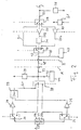
- Fig. 1 shows the circuit diagram of an arrangement, e.g. is integrated in a road vehicle.
- an outdoor antenna of the mobile subscriber station is designated.
- An external antenna is understood to mean an antenna for transmitting and / or receiving radio signals to the outside or from outside the subscriber station, the radio signals being transmitted within a mobile radio network.
- the antenna 21 is connected to a diplexer 23 having a high pass filter 23a and a low pass filter 23b.
- the diplexer 23 serves to operate the arrangement for transmitting signals in different frequency ranges, e.g. both in the frequency range of the mobile radio standard GSM1800 and the mobile radio standard GSM900.
- the diplexer it is also possible to provide a diplexer for a different number of frequency bands, so that the arrangement (this also applies to the arrangements according to FIGS. 2 and 3), e.g. is also suitable for a UMTS mobile network.
- the arrangement shown in FIG. 1 has a second diplexer 25 with a high-pass filter 25a and a low-pass filter 25b.
- two branches 24a, 24b of the antenna feed line are arranged, each at one of its ends with the low-pass filter 23b and the Low-pass filter 25b (in the case of the branch 24b) and with the high-pass filter 23a and the high-pass filter 25a (in the case of the branch 24a) are connected.
- the two branches 24a, 24b are constructed essentially identical, for which reason the same reference numerals are used in FIG. 1 for elements of the two branches 24a, 24b.
- a respective switch 26, 28 is connected directly via a section of the antenna feed line and serves to switch over the signal path to respectively one of two sub-branches 27a, 27b.
- the switch can be, for example, an SPDT analog switch (single-pole / double-throw analog switch). As shown by a dashed line in Fig. 1, the switching state of the switches 26, 28 is controlled via a signal line.
- the sub-branch 27a which has a second signal amplifier 29 for amplifying the signals which have been received by the antenna 21 and transmitted via the antenna feed line.
- the second amplifier 29 is e.g. a LNA (Low Noise Amplifer). Since the signals received via the antenna 21 may be very weak signals, i. Signals with a high noise component, can act, it is preferred that the second signal amplifier 29 is connected via a shortest possible path of the antenna feed line to the antenna 21. It is particularly preferred that the diplexer 23 (or another crossover), the switch 26 and at least also the second signal amplifier 29 are integrated in the antenna base of the antenna.
- An antenna base is understood to mean that mechanical part of an antenna arrangement with which the antenna is mechanically fastened to the mobile radio subscriber station.
- said part of the arrangement can also be arranged outside the antenna base, but in the immediate vicinity of the antenna base.
- the length of the path of the antenna feed line from the antenna base to the second signal amplifier is a maximum of 1.5 m, preferably a maximum of 30 cm.
- the entire illustrated part of the arrangement is located in the antenna base or in the vicinity of the antenna base.
- Fig. 2 still another arrangement described, which has fewer components and therefore can be more easily integrated into the antenna base.
- the second sub-branch 27b has a first signal amplifier 30 which serves to amplify signals to be transmitted to the antenna 21 and to be transmitted from the antenna 21 to the mobile radio network.
- the first signal amplifier is, in particular, a power amplifier with which the signals to be transmitted can be sufficiently amplified in order to be able to be transmitted in the mobile radio network.
- a harmonic filter 31 is connected in series with the first signal amplifier 30, which has a low-pass effect.
- a part of the antenna feed line starts, via which all signals to be transmitted via the antenna feed line between the subscriber terminal and the antenna 21 are transmitted (common path 33).
- a detector 35 is connected to the common path 33. As shown by two dashed lines, which attach to the detector 35, this is connected via signal lines to the switches 26, 28, so that depending on the signals on the common path 33, the switch positions of the switches 26, 28 of the detector 35 can be controlled.
- the detector 35 is connected to the power amplifiers 30 via the signal lines. He is therefore also able to control the transmission power of the power amplifier 30.
- the detector may detect control signals transmitted via the common path 33, and depending on which control the switches and / or amplifiers.
- a digitally adjustable attenuator 37 On the common path 33 is also a digitally adjustable attenuator 37, the attenuation can be adjusted by a device that is not shown in Fig. 1. Referring to Fig. 4, such a device will be discussed.
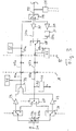
- FIG. 2 The embodiment according to FIG. 2 will now be described. However, only those parts of the arrangement are described in which the arrangement of the arrangement shown in Fig. 1 differs. Gielche and functionally identical elements and devices are denoted by the same reference numerals as in Fig. 1. This also applies to the still to be described Fig, 3rd
- the received signals in turn reach the diplexer 23.
- a switch 38 is provided, which is connected directly to the switch 26 for the signals to be transmitted via the antenna 21.
- the switch 38 may be, for example, a 3: 1 multiplexer, in particular a single-pole / triple-throw analog switch (SP3T).
- SP3T single-pole / triple-throw analog switch
- the signals received by the antenna 21 from the switch 26 in the direction of subscriber terminal is in the arrangement for the frequency bands each have a second signal amplifier 29 whose output is connected to a combiner 39, which the output signals of the amplifier 29 again combined a common path 41 of the received signals.
- the combiner 39 may be e.g. to trade a diplexer. An output of the combiner 39 is connected to a terminal of the switch 38 via the common path 41 of the received signals.
- a part of the common path 33 of all signals to be transmitted via the antenna feed line which in turn is connected to the detector 35 for controlling the switches 26, 38, sets on the switch 38.
- the detector 35 does not control the power amplifiers.
- a line 42 is connected to the common path 33, via which can be coupled to the power supply, in particular the amplifier 29 electrical current from the common path 33, i. can be diverted.
- the devices to be supplied with electrical energy via this decoupled current are shown schematically by the block designated by reference numeral 44.
- the block 44 also contains other elements for power supply.
- Such a power supply via the common path 33 may also be provided in other embodiments of the invention. It is particularly advantageous if the parts to be supplied with power, elements and facilities are arranged in a hard to reach area.
- all elements and devices to the left of the vertical dashed line labeled A are part of an antenna arrangement, wherein (with the exception of the antenna 21 itself) all other elements and devices can be integrated in particular in the antenna base. Since this part of the overall arrangement does not contain the power amplifiers as in FIG. 1, integration into the antenna base and / or elsewhere in a miniaturized form is all the easier.
- a coaxial cable 45 which, in practice, can be made much longer in comparison to the other illustrated pathways, e.g. the antenna arrangement at the rear of a road motor vehicle (eg passenger cars) connects to the rest of the arrangement in the middle or front area of the vehicle. This remainder is partially illustrated in FIG. 2 to the right of the vertical dashed line indicated by the reference B.
- the part has a device 47 which is connected via a line 48 to the common path 33 and the coupling of electrical current is used, which is coupled via the line 42.
- the common path 33 is connected to a second 3-way switch 58. Again, this may be a 3: 1 multiplexer, in particular an SP3T.
- One of the three terminals of the switch 58, to which the signal flow of the common path 33 can be switched, is connected via a continuous line connection 51 to a corresponding terminal of a further switch 59, which in turn is a 3: 1 multiplexer, e.g. an SP3T, can be.
- This line connection 51 serves to transmit control signals via the common path 33 in the area B, the coaxial cable 45 and the other part of the common path 33 in the antenna arrangement (area A).
- these control signals may be used by the detector 35 to control the switches 26, 38 and / or the amplifier power of the amplifiers 29.
- the sub-branches 27b are also arranged, which correspond to the sub-branches 27b according to FIG. 1 and have the power amplifiers 30.
- the common path 33 From the perspective of the sub-branches 27b beyond the switch 59 is another portion of the common path 33, to which a further detector 55 for controlling the switching states of the switches 58, 59 and the amplifier power of Power amplifier 30 is connected.
- a further detector 55 for controlling the switching states of the switches 58, 59 and the amplifier power of Power amplifier 30 is connected.
- this part of the common path 33 of the remaining part of the overall arrangement is connected, which is not shown in Fig. 2.
- This remaining part has, for example (with the exception of the coaxial cable shown there) on elements and devices which will be described with reference to FIG. 4.
- These include in particular the adjustable attenuator 37 with the associated adjusting device, a connection device for connecting the device to a subscriber terminal, the signal generation for transmitting the control signals for the actuating device via the antenna feed line and the signal detection.
- FIG. 2 also shows a device 61 for the power supply, which symbolizes the vehicle electrical system for supplying consumers with electrical energy, for example in a road vehicle.
- the device 61 is connected to the means 47 for coupling the current in the common path 33.
- FIG. 3 shows a modification of the arrangement according to FIG. 2, the essential difference being that, instead of the one coaxial cable 45, both the transmission signals (ie for transmission from the antenna 21 to the mobile radio network) and the reception signals (ie the signals two coaxial cables (or other line connections) 45a, 45b are provided for separately transmitting the signals in the transmission direction and reception direction.
- a switch 67 is provided in the antenna arrangement, which may be a 2: 1 multiplexer, in particular an SPDT.
- the common path 33b for the transmission signals connected to this switch 67 leads via the coaxial cable 45b to a switch 68 in the remote part of the arrangement (in area B).
- the output of the combining device 39 is connected via a common path 33 a which is common Path is only for the received signals, and connected via a coaxial cable 45a with the removed part of the arrangement.
- the common path 33a ends at the switch 59 and goes back into the common path 33 of all signals.
- a device 52 for coupling control signals in the remote part of the arrangement on the common path 33 a is shown in the upper right in Fig. 3.
- the control signals coupled in this way can be coupled out of the common path 33a by the detector 35 of the antenna arrangement.
- the attenuator 37 is connected via a control signal line 71, e.g. digital signals with a resolution of 5 bits, connected to a detection device 73.
- the detection device 73 is configured to send control signals for adjusting the degree of damping of the damping device 37 via the control signal line 71.
- the detection device 73 has e.g. a ROM (Read Only Memory).
- An input of the detection device 73 is connected to the common path 33 of the antenna feed line via a series connection of a DC blocking device 75 (with, for example, a capacitor) and a low-pass filter 77.
- a DC blocking device 75 with, for example, a capacitor
- a low-pass filter 77 In a variant of this part of the arrangement, which can be connected to the arrangement according to FIG. 3, it may also be the common path 33a for the received signals and / or the common path 33b for all signals instead of the common path 33 all transmission signals act.
- the detection device in which the detection device is controlled by frequency signals, is also on the common path 33, in a section between the subscriber terminal and the damping device 37, between the connection point of the series circuit 75, 77 and the damping device 37, a high-pass filter 79 is arranged.
- the detection device 73 can be controlled via frequency signals which are low-frequency compared to the actual signals to be transmitted.
- the detection device 73 can set the corresponding degree of damping of the damping device 37.
- this is stored, for example, which low-frequency frequency corresponds to which bit value which is to be transmitted via the signal line 71.
- the attenuator and the previously described parts of the arrangement are part of the antenna arrangement.
- This part is connected via a coaxial cable 45 to the part of the device (viewed from the antenna).
- the common path 33 via a connection point 81 with a second series circuit of a DC blocking device 85 and a low-pass filter 87 with a frequency generator, 89, in Fig. 4 is indicated by the symbols f 1 , f 2 that the frequency generator 89th Frequency generator 89 preferably generates only one frequency signal at a given time, and the frequency of this signal is constant over time and only changes when the terminal attenuation has changed. This is the case, for example, when a mobile phone is connected in a different way to the antenna feed line and / or another mobile phone is connected to the antenna feed line.
- a plurality of frequency generators may also be provided or optionally part of the arrangement.
- each of the frequency generators is set to a fixed frequency.
- the frequency generator provided or available for a specific connection attenuation is only activated or connected to the arrangement when a subscriber terminal with this connection attenuation is connected to the antenna feed line.
- a motor vehicle may have an electrical connection, via which antenna signals of a mobile telephone can be coupled in directly and essentially without loss losses or can be coupled out.
- the vehicle may have a housing into which a terminal can be inserted and an in The housing arranged antenna coupler can be wirelessly connected to the antenna feed line.
- a frequency generator may be provided, which is preferably activated automatically when connecting the terminal.
- the electrical connection is designated by the reference symbol 91 and the antenna coupler is designated by the reference symbol 93.
- the terminal here a mobile phone, is designated by reference numeral 95.
- a second high-pass filter 97 is arranged between the contact point 81 for the branch of the frequency generator and the terminal for the terminal.
- the invention is not limited to this combination of connection types.
- another signal generating means may be provided which generates, for example, a DC signal.
- that part of the arrangement which serves to amplify the transmitter signals may be integrated in the electromagnetic shielding housing.
- These include in particular the power amplifier or include the power amplifier for different frequency bands.
- the switches 58 and 59 or 68 and 59 may also belong to it.
- the amplifiers for the transmission signals or for the reception signals can also be replaced by a single amplifier which takes over the amplification for different frequency bands.
- the amplifier can be adjusted to the frequency band used.
- a housing 1 may be provided which has a lower part 2 and a cover 9.
- the lower part 2 surrounds an inner space of the housing 1 on all sides except the upper side.
- the lower part 2 is configured substantially cuboid, but has rounded corners and forms an upper edge 6 for supporting a trough-shaped insert part 5.
- the lower part 2 is z. B. of metal manufactured (and may optionally be connected to the ground potential of the motor vehicle), so that it dampens electromagnetic waves that pass through the lower part 2, and / or so that electromagnetic waves can not pass through the lower part 2. In both cases, a shielding effect is achieved.
- the trough-shaped insert 5 defines, inside the housing 1, a partial interior space 11 which is large enough to be arranged in each case a mobile telephone, wherein the mobile telephone can be selected from a large number of different types, wherein the external dimensions of the mobile phones in a wide Range can vary.
- the extending from right to left in Fig. 1 length of the cellphone 7 shown there fills the part of the interior space 11 is not.
- the insert 5 forms a shoulder, ie a region located laterally of the part inner space 11, in which it extends above the level of the support surface for the mobile telephone 7 in an approximately horizontal direction. From this level, the material of the insert 5 then rises to the level of the edge 6 of the lower part 2. At said intermediate level is in the closed state of the housing 1 shown in Fig. 5, a foam plate 8 is placed on the underside of the lid 9 can be attached. The height or thickness of the foam plate 8 is dimensioned such that it extends from the lower surface of the lid 9 to the intermediate level and rests there on the shoulder of the insert 5.
- the height of the insert 5 in the area of the sub-interior 11 in which the mobile phone 7 or other mobile phones can be arranged is such that the thickness of mobile phones having a thickness in the usual range (the thickness is the dimension, the in Fig. 5 extends in the vertical direction) is greater than the height between the support surface for the mobile phone 7 to the top of the shoulder.
- the mobile phone protrudes beyond the level of the shoulder and therefore presses the foam plate 8 with the lid 9 closed on the mobile phone, as shown in FIG. 1 and FIG. 2 can be seen. Therefore, the foam of the foam sheet 8 is compressed (not shown in Fig. 1 and Fig. 2) and exerts due to the resulting elastic deformation of a pressing force on the mobile phone 7, which presses the mobile phone in addition to its weight on the support surface of the insert 5.
- the foam sheet 8 is made of a material which causes high dielectric losses in electromagnetic waves passing through, in particular in the frequency ranges used by mobile phones, so that the waves are damped and a shielding effect is achieved.
- carbon is distributed in the foam material which causes at least the substantial portion of the dielectric losses.
- the foam material may be polyurethane foam, for example.
- C-RAM MT homogeneous damping foam
- a circuit board 3 is arranged in the space between the bottom of the lower part 2 and the part-inner space 11 (trough), in which the mobile phone 7 is arranged. Electrical components and circuit elements as well as other devices may be formed on the circuit board 3. In lieu of a printed circuit board, another body may be provided which carries such devices. These devices may in particular perform functions which serve for the operation of the mobile telephone 7 or another mobile telephone in the housing 1 or in another housing. In particular, the devices may be formed on the board 3 or the other body as an antenna structure, so that between the antenna structure and the antenna of the mobile phone radio signals can be transmitted. The antenna structure is in turn connected via a bushing 4 through the housing to the antenna feed of the vehicle antenna.
- a first signal amplifier and / or a second antenna structure for a Bluetooth interface between the mobile phone and the devices on the board 3 or the other body
- the mobile phone can use the Bluetooth interface be connected in a known manner to a hands-free device of the motor vehicle with at least one speaker and with at least one microphone.
- a suitable arrangement for signal amplification is z. In DE 10114531 described.
Landscapes
- Engineering & Computer Science (AREA)
- Computer Networks & Wireless Communication (AREA)
- Signal Processing (AREA)
- Mobile Radio Communication Systems (AREA)
Applications Claiming Priority (1)
| Application Number | Priority Date | Filing Date | Title |
|---|---|---|---|
| DE102006021514A DE102006021514A1 (de) | 2006-05-04 | 2006-05-04 | Anordnung zur Übertragung von Signalen über eine Antennenzuleitung in einer Mobilfunk-Teilnehmerstation |
Publications (1)
| Publication Number | Publication Date |
|---|---|
| EP1852978A2 true EP1852978A2 (fr) | 2007-11-07 |
Family
ID=38325512
Family Applications (1)
| Application Number | Title | Priority Date | Filing Date |
|---|---|---|---|
| EP07008932A Withdrawn EP1852978A2 (fr) | 2006-05-04 | 2007-05-03 | Dispositif de surveillance de signaux par une conduite d'antennes dans un poste d'abonné de radio mobile |
Country Status (3)
| Country | Link |
|---|---|
| US (1) | US20070281631A1 (fr) |
| EP (1) | EP1852978A2 (fr) |
| DE (1) | DE102006021514A1 (fr) |
Cited By (2)
| Publication number | Priority date | Publication date | Assignee | Title |
|---|---|---|---|---|
| EP2493081A3 (fr) * | 2011-02-28 | 2013-10-16 | Funkwerk Dabendorf GmbH | Agencement d'émission et de réception de signaux radio pour le fonctionnement stationnaire d'un terminal radio et procédé de fabrication d'un tel agencement |
| DE102013101590A1 (de) | 2013-02-18 | 2014-08-21 | Bury Sp.Z.O.O | Schaltungsanordnung zur Kompensation einer in einer Antennensignalverbindung zwischen einem Mobilfunkendgerät und einer Antenne auftretenden Dämpfung sowie Verfahren zur Kompensation hierzu |
Families Citing this family (4)
| Publication number | Priority date | Publication date | Assignee | Title |
|---|---|---|---|---|
| DE102008040395B3 (de) * | 2008-07-14 | 2009-11-12 | Funkwerk Dabendorf Gmbh | Detektionsschaltung |
| US8446334B2 (en) * | 2009-05-22 | 2013-05-21 | Galtronics Corporation Ltd. | Multi-antenna multiband system |
| DE102017209209A1 (de) * | 2017-05-31 | 2018-12-06 | Laird Dabendorf Gmbh | Signalkopplungsvorrichtung und Verfahren zum Betrieb einer Signalkopplungsvorrichtung |
| DE102018213029A1 (de) | 2018-08-03 | 2020-02-06 | Audi Ag | Sende-/Empfangssystem für Funksignale |
Family Cites Families (13)
| Publication number | Priority date | Publication date | Assignee | Title |
|---|---|---|---|---|
| US5734352A (en) * | 1992-08-07 | 1998-03-31 | R. A. Miller Industries, Inc. | Multiband antenna system |
| JPS6485431A (en) * | 1987-09-28 | 1989-03-30 | Toshiba Corp | Radio telephone system |
| US5026532A (en) * | 1989-04-06 | 1991-06-25 | Air Products And Chemicals, Inc. | Process for the preparation of an improved chabazite for the purification of bulk gases |
| DE4008632C2 (de) * | 1990-03-17 | 1994-05-19 | Bosch Gmbh Robert | Antennenweiche |
| FI89120C (fi) * | 1991-09-24 | 1993-08-10 | Nokia Mobile Phones Ltd | Effektinstaellning i en boosterfoerstaerkare |
| WO1994018761A1 (fr) * | 1993-02-05 | 1994-08-18 | Kabushiki Kaisha Toshiba | Telephone sans fil |
| JPH06276146A (ja) * | 1993-03-19 | 1994-09-30 | Fujitsu Ltd | 移動電話装置 |
| US5557287A (en) * | 1995-03-06 | 1996-09-17 | Motorola, Inc. | Self-latching antenna field coupler |
| GB2306056B (en) * | 1995-10-06 | 1999-12-08 | Nokia Mobile Phones Ltd | Antenna |
| WO2001095507A2 (fr) * | 2000-06-09 | 2001-12-13 | Daimlerchrysler Ag | Agencement pour faire fonctionner plusieurs terminaux |
| US6892080B2 (en) * | 2001-11-27 | 2005-05-10 | Arrista Technologies, Inc. | Booster amplifier for cellular telephone cradles |
| US7010325B1 (en) * | 2002-06-11 | 2006-03-07 | Sprint Spectrum L.P. | Wireless repeater with wireless telephone adapter |
| US7221967B2 (en) * | 2004-09-14 | 2007-05-22 | Wilson Electronics, Inc. | Enhanced gain selected cell phone booster system |
-
2006
- 2006-05-04 DE DE102006021514A patent/DE102006021514A1/de not_active Withdrawn
-
2007
- 2007-04-27 US US11/796,571 patent/US20070281631A1/en not_active Abandoned
- 2007-05-03 EP EP07008932A patent/EP1852978A2/fr not_active Withdrawn
Cited By (4)
| Publication number | Priority date | Publication date | Assignee | Title |
|---|---|---|---|---|
| EP2493081A3 (fr) * | 2011-02-28 | 2013-10-16 | Funkwerk Dabendorf GmbH | Agencement d'émission et de réception de signaux radio pour le fonctionnement stationnaire d'un terminal radio et procédé de fabrication d'un tel agencement |
| DE102013101590A1 (de) | 2013-02-18 | 2014-08-21 | Bury Sp.Z.O.O | Schaltungsanordnung zur Kompensation einer in einer Antennensignalverbindung zwischen einem Mobilfunkendgerät und einer Antenne auftretenden Dämpfung sowie Verfahren zur Kompensation hierzu |
| CN104022790A (zh) * | 2013-02-18 | 2014-09-03 | 布里公司 | 用于补偿天线信号连接中出现的衰减的电路装置及方法 |
| CN104022790B (zh) * | 2013-02-18 | 2018-03-30 | 布里公司 | 用于补偿天线信号连接中出现的衰减的电路装置及方法 |
Also Published As
| Publication number | Publication date |
|---|---|
| DE102006021514A1 (de) | 2007-11-15 |
| US20070281631A1 (en) | 2007-12-06 |
Similar Documents
| Publication | Publication Date | Title |
|---|---|---|
| EP2011243B2 (fr) | Dispositif de couplage et de réception d'un téléphone mobile à l'intérieur d'un véhicule automobile | |
| DE60221150T2 (de) | Antennensystem | |
| DE69806405T2 (de) | Unabhängige mastmontierte einheit für zellularkommunikationsnetze | |
| DE102008059333A1 (de) | GPS-Mastmodul sowie Mobilfunkanlage | |
| EP1852978A2 (fr) | Dispositif de surveillance de signaux par une conduite d'antennes dans un poste d'abonné de radio mobile | |
| EP2028055A2 (fr) | Dispositif de couplage et de réception d'un téléphone mobile à l'intérieur d'un véhicule automobile | |
| EP1371144B1 (fr) | Circuit destine a compenser l'affaiblissement dans un cable d'alimentation d'antenne pour un appareil radiomobile | |
| DE102006010963A1 (de) | Mehrbandfähige Schaltungsanordnung zur Dämpfungskompensation in einem Antennenzuleitungskabel | |
| EP1295402B1 (fr) | Agencement pour faire fonctionner plusieurs terminaux | |
| DE102017131088B4 (de) | Mobilfunkkompensator zum Einsatz in Kraftfahrzeugen und ein solches Kraftfahrzeug | |
| DE69431218T2 (de) | Verfahren zur Bedienung eines Funktelefons | |
| DE19913064C1 (de) | Schaltungsanordnung zur Dämpfungskompensation | |
| EP3836565B1 (fr) | Carte de circuit imprimé d'un appareil auditif | |
| EP0782213B1 (fr) | Station radioélectrique avec une unité d'antenne séparée | |
| WO2016162125A1 (fr) | Compensateur servant à compenser des pertes de ligne et/ou de couplage | |
| DE10313625A1 (de) | Aufnahmevorrichtung für ein Mobilfunkgerät | |
| EP1371143B1 (fr) | Circuit destine a compenser l'affaiblissement dans un cable d'alimentation d'antenne pour un appareil radiomobile | |
| EP2755329A2 (fr) | Circuit d'amplification de compensation destiné à être intégré dans une ligne de transmission entre un appareil radio mobile situé dans un véhicule automobile ou un logement côté véhicule automobile pour l'appareil radio mobile d'une part et une antenne du véhicule automobile d'autre part, et procédé de fonctionnement d'un circuit d'amplification de compensation bidirectionnel correspondant | |
| DE102010018509B9 (de) | Senden und Empfangen von Funksignalen in verschiedenen Frequenzbereichen | |
| DE19514993A1 (de) | Antennenverstärker | |
| DE10026152A1 (de) | Drahtloses Sendeempfangsgerät | |
| DE60102578T2 (de) | Sender für Mobiles Telekommunikationsendgerät | |
| DE102010045244A1 (de) | Kompensation der Dämpfung in einer Hochfrequenzleitung zwischen einer Mobilfunkstation und einer Antenne | |
| DE10352290A1 (de) | Antennenverstärker | |
| DE102008053851A1 (de) | Antennenanlage, insbesondere Mobilfunk-Antennenanlage sowie zugehörige Übertragungs- und Steuerungseinrichtung |
Legal Events
| Date | Code | Title | Description |
|---|---|---|---|
| PUAI | Public reference made under article 153(3) epc to a published international application that has entered the european phase |
Free format text: ORIGINAL CODE: 0009012 |
|
| AK | Designated contracting states |
Kind code of ref document: A2 Designated state(s): AT BE BG CH CY CZ DE DK EE ES FI FR GB GR HU IE IS IT LI LT LU LV MC MT NL PL PT RO SE SI SK TR |
|
| AX | Request for extension of the european patent |
Extension state: AL BA HR MK YU |
|
| STAA | Information on the status of an ep patent application or granted ep patent |
Free format text: STATUS: THE APPLICATION IS DEEMED TO BE WITHDRAWN |
|
| 18D | Application deemed to be withdrawn |
Effective date: 20111201 |