EP2028055A2 - Dispositif de couplage et de réception d'un téléphone mobile à l'intérieur d'un véhicule automobile - Google Patents
Dispositif de couplage et de réception d'un téléphone mobile à l'intérieur d'un véhicule automobile Download PDFInfo
- Publication number
- EP2028055A2 EP2028055A2 EP08075695A EP08075695A EP2028055A2 EP 2028055 A2 EP2028055 A2 EP 2028055A2 EP 08075695 A EP08075695 A EP 08075695A EP 08075695 A EP08075695 A EP 08075695A EP 2028055 A2 EP2028055 A2 EP 2028055A2
- Authority
- EP
- European Patent Office
- Prior art keywords
- coupling
- mobile telephone
- coupling unit
- mobile phone
- antenna
- Prior art date
- Legal status (The legal status is an assumption and is not a legal conclusion. Google has not performed a legal analysis and makes no representation as to the accuracy of the status listed.)
- Withdrawn
Links
- 230000008878 coupling Effects 0.000 title claims abstract description 110
- 238000010168 coupling process Methods 0.000 title claims abstract description 110
- 238000005859 coupling reaction Methods 0.000 title claims abstract description 110
- 238000000034 method Methods 0.000 title claims abstract description 16
- 239000000463 material Substances 0.000 claims description 11
- 230000005540 biological transmission Effects 0.000 description 12
- 239000004020 conductor Substances 0.000 description 5
- 238000005516 engineering process Methods 0.000 description 5
- 238000003032 molecular docking Methods 0.000 description 5
- 230000009466 transformation Effects 0.000 description 5
- 230000006978 adaptation Effects 0.000 description 4
- 230000008859 change Effects 0.000 description 4
- 239000006260 foam Substances 0.000 description 4
- 238000009434 installation Methods 0.000 description 4
- 230000005236 sound signal Effects 0.000 description 4
- 230000007704 transition Effects 0.000 description 4
- 230000008901 benefit Effects 0.000 description 3
- 238000013461 design Methods 0.000 description 3
- 239000002184 metal Substances 0.000 description 3
- 239000000919 ceramic Substances 0.000 description 2
- 230000005489 elastic deformation Effects 0.000 description 2
- 238000003780 insertion Methods 0.000 description 2
- 230000037431 insertion Effects 0.000 description 2
- 230000008569 process Effects 0.000 description 2
- 230000008054 signal transmission Effects 0.000 description 2
- 239000000126 substance Substances 0.000 description 2
- 230000003321 amplification Effects 0.000 description 1
- 230000002238 attenuated effect Effects 0.000 description 1
- 239000000969 carrier Substances 0.000 description 1
- 238000005291 chaos (dynamical) Methods 0.000 description 1
- 238000006243 chemical reaction Methods 0.000 description 1
- 230000000295 complement effect Effects 0.000 description 1
- 150000001875 compounds Chemical class 0.000 description 1
- 239000003989 dielectric material Substances 0.000 description 1
- 238000006073 displacement reaction Methods 0.000 description 1
- 239000013013 elastic material Substances 0.000 description 1
- 238000004870 electrical engineering Methods 0.000 description 1
- 238000012983 electrochemical energy storage Methods 0.000 description 1
- 239000003822 epoxy resin Substances 0.000 description 1
- 239000006261 foam material Substances 0.000 description 1
- 239000003365 glass fiber Substances 0.000 description 1
- 230000036541 health Effects 0.000 description 1
- 230000010354 integration Effects 0.000 description 1
- 230000007246 mechanism Effects 0.000 description 1
- 239000000203 mixture Substances 0.000 description 1
- 238000010295 mobile communication Methods 0.000 description 1
- 238000003199 nucleic acid amplification method Methods 0.000 description 1
- 230000003287 optical effect Effects 0.000 description 1
- 238000005498 polishing Methods 0.000 description 1
- 229920000647 polyepoxide Polymers 0.000 description 1
- -1 polytetrafluoroethylene Polymers 0.000 description 1
- 229920001343 polytetrafluoroethylene Polymers 0.000 description 1
- 239000004810 polytetrafluoroethylene Substances 0.000 description 1
- 239000000843 powder Substances 0.000 description 1
- 238000012545 processing Methods 0.000 description 1
- 230000005855 radiation Effects 0.000 description 1
- 230000035939 shock Effects 0.000 description 1
Images


Classifications
-
- B—PERFORMING OPERATIONS; TRANSPORTING
- B60—VEHICLES IN GENERAL
- B60R—VEHICLES, VEHICLE FITTINGS, OR VEHICLE PARTS, NOT OTHERWISE PROVIDED FOR
- B60R11/00—Arrangements for holding or mounting articles, not otherwise provided for
- B60R11/02—Arrangements for holding or mounting articles, not otherwise provided for for radio sets, television sets, telephones, or the like; Arrangement of controls thereof
- B60R11/0241—Arrangements for holding or mounting articles, not otherwise provided for for radio sets, television sets, telephones, or the like; Arrangement of controls thereof for telephones
-
- B—PERFORMING OPERATIONS; TRANSPORTING
- B60—VEHICLES IN GENERAL
- B60R—VEHICLES, VEHICLE FITTINGS, OR VEHICLE PARTS, NOT OTHERWISE PROVIDED FOR
- B60R11/00—Arrangements for holding or mounting articles, not otherwise provided for
- B60R2011/0001—Arrangements for holding or mounting articles, not otherwise provided for characterised by position
- B60R2011/0003—Arrangements for holding or mounting articles, not otherwise provided for characterised by position inside the vehicle
- B60R2011/0005—Dashboard
-
- B—PERFORMING OPERATIONS; TRANSPORTING
- B60—VEHICLES IN GENERAL
- B60R—VEHICLES, VEHICLE FITTINGS, OR VEHICLE PARTS, NOT OTHERWISE PROVIDED FOR
- B60R11/00—Arrangements for holding or mounting articles, not otherwise provided for
- B60R2011/0042—Arrangements for holding or mounting articles, not otherwise provided for characterised by mounting means
- B60R2011/0043—Arrangements for holding or mounting articles, not otherwise provided for characterised by mounting means for integrated articles, i.e. not substantially protruding from the surrounding parts
- B60R2011/0045—Arrangements for holding or mounting articles, not otherwise provided for characterised by mounting means for integrated articles, i.e. not substantially protruding from the surrounding parts with visible part, e.g. flush mounted
-
- B—PERFORMING OPERATIONS; TRANSPORTING
- B60—VEHICLES IN GENERAL
- B60R—VEHICLES, VEHICLE FITTINGS, OR VEHICLE PARTS, NOT OTHERWISE PROVIDED FOR
- B60R11/00—Arrangements for holding or mounting articles, not otherwise provided for
- B60R11/02—Arrangements for holding or mounting articles, not otherwise provided for for radio sets, television sets, telephones, or the like; Arrangement of controls thereof
- B60R2011/027—Arrangements for holding or mounting articles, not otherwise provided for for radio sets, television sets, telephones, or the like; Arrangement of controls thereof for Din-sized apparatus
Definitions
- the invention relates to an arrangement for coupling a mobile phone to devices of a motor vehicle and in particular for receiving the mobile phone within the motor vehicle.
- the invention further relates to a method for coupling and arranging the mobile phone in the motor vehicle.
- a mobile telephone means a device that can communicate with a remote station via a radio interface while it is being moved.
- the device does not necessarily have a keyboard and is not necessarily suitable for both the transmission mode and the reception mode.
- the mobile phone may be a mobile emergency transmitter that sends an emergency signal to the station at the push of a button.
- a mobile phone can be kept within a motor vehicle at a desired location.
- connections for electrical coupling (connecting) of the mobile phone to a hands-free system and / or to an antenna of the motor vehicle are integrated.
- the mobile phone can be connected via a Bluetooth radio interface with the built-in car in the car kit.
- the holders are usually suitable only for a particular design of mobile phones. If another type of mobile phone is to be held, a new holder or at least a new adapter is usually required.
- a receiving device for a mobile device with holding means for fixing the mobile device with a predetermined holding position and a coupling antenna is designed and arranged such that there is a wireless coupling between a mobile device antenna of the mobile device and the coupling antenna when befindlichem in the holding position mobile device.
- the transmission power of the wireless coupling is kept low and also an amplifier element is provided which amplifies signals in a transmission line to an external antenna of a motor vehicle.
- the coupling unit has a hands-free device. Further, the coupling unit has a recess (hereinafter also referred to as a recess), so that in a state in which the coupling unit is installed in the motor vehicle, the mobile phone is at least partially introduced into the recess.
- the coupling unit has a coupling device for wireless coupling of the mobile phone to the hands-free device in order to enable a hands-free operation via the coupling device.
- a hands-free device is a device that allows people in the vehicle to make phone calls without having to hold the mobile phone in their hands.
- at least one microphone and / or at least one loudspeaker can be integrated into the hands-free system.
- at least one microphone and / or at least one loudspeaker are connected in each case via an electrical connection to the hands-free device.
- the received voice signals are converted via the at least one speaker into acoustic signals and will receive sounds in the vehicle interior via the at least one microphone, so that corresponding signals can be transmitted via the mobile telephone network to other participants in the conversation.
- the speaker or speakers may be arranged so that the acoustic signals in the vehicle interior can be heard.
- at least one speaker can be designed as an ear speaker for only one person, the z. B. attachable to the ear of the person.
- the handsfree since the mobile phone is wireless, i. without electrically conductive connection, is coupled to the handsfree, the handsfree has at least the function to operate the wireless connection for transmitting the output signals and / or transmission of the recorded sound signals.
- the wireless connection can be z. B. a connection according to the Bluetooth standard (IEEE 802.15.1). However, other types of compounds are possible, for. B. infrared connections.
- the wireless connection of the mobile phone to the speakerphone does not exclude that z. B. for connecting the mobile phone to a battery charging device and an electrical connection between the mobile phones and the coupling unit or other devices is made in the motor vehicle.
- An advantage of the integration of a coupling device in the coupling unit is that the coupling device can be optimally arranged and aligned with respect to the space for receiving a mobile phone.
- the coupling device, or a further coupling device of the coupling unit can be designed for wireless coupling of the mobile phone to an antenna (in particular an external antenna of the motor vehicle).
- an antenna in particular an external antenna of the motor vehicle.
- the coupling device may have one or more antenna structures.
- an antenna structure eg, via a coaxial cable
- an external antenna of the motor vehicle may be connected to an external antenna of the motor vehicle. In this way, radio signals that are emitted by the mobile phone from the antenna structure inside the motor vehicle can be received via the connection to the outer antenna of the motor vehicle and emitted by the latter.
- the signals can be changed and / or processed after their reception by the antenna structure, but before they are transmitted via the external antenna.
- additional information can be added to the information to be transmitted and / or it is possible to proceed to a different data format and / or transmission protocol.
- the coupling of the mobile telephone to the antenna structure allows reception of signals initially received by the outside antenna, transmitted to the antenna structure via the connection between the outside antenna and the antenna structure, and wirelessly transmitted from the antenna structure to the receiving antenna of the mobile telephone the transmitting and receiving antenna of the mobile phone can also be a single antenna.
- processing and / or variation of the information contained in the reception signals can be performed.
- the recess into which the mobile phone can be at least partially (and preferably completely) introduced may be a receiving space in the coupling unit, wherein the receiving space has an opening through which the mobile phone is wholly or partially introduced into the receiving space.
- all walls of the receiving space can be formed by the coupling unit.
- the coupling unit forms a cavity an externally accessible opening through which the mobile phone can be introduced into the receiving space or can be removed from the receiving space.
- the recess but z. B. be formed on the upper side of the coupling unit, so that the coupling unit forms only a part of the walls of the receiving space. Another part of the walls in this case z. B. formed by parts of the motor vehicle, when the coupling unit is installed in the motor vehicle.
- the recess offers space for the optional introduction of mobile phones with different dimensions.
- an embodiment is preferred in which optionally mobile phones with different dimensions are introduced into the recess.
- the recess has a support surface for placing the mobile telephone, wherein the support surface is formed by a non-slip material.
- the non-slip material is z. B. a rubber material, preferably with a profiled (eg., Grooves and / or surveys having) surface.
- the recess has a support surface for placing the mobile telephone, wherein the support surface is bounded by a raised edge.
- the edge defines the support surface to the outside and is formed in particular at the opening through which the mobile phone can be introduced into the recess or in the receiving space.
- the opening of the receiving space may be defined by an object (such as a flap hinged to the door) Coupling unit is hinged) completely or partially blocked. It is also possible to fill the recess at least partially with elastic materials before and / or after the introduction of the mobile telephone into the receiving space.
- the receiving space can be partially filled with two blocks of foam, between which the mobile phone can be inserted and is held due to the elastic deformation of the blocks between them.
- Conceivable although not preferred, is the use of a holding chamber, which holds the mobile phone in the receiving space.
- the retaining clip should be as possible as possible to hold different types of mobile phone firmly.
- At least part of the walls of the receiving space can be moved by a motor or a manually operated movement mechanism. After insertion of the mobile phone into the receiving space, the movable part of the walls can be moved so that the mobile phone is clamped to the walls and optionally other objects within the receiving space. To remove the mobile phone, proceed in reverse order. First, the movable part of the walls is moved so that the mobile phone is released and then the mobile phone is removed from the receiving space.
- An advantage of the invention is precisely that different types of mobile phones can be coupled via the coupling device to the coupling unit.
- an antenna structure of the docking device (as will be described) leaves a wide margin for the arrangement of the mobile phone in the receiving space (ie the coupling via the antenna structure works well even if a mobile phone is located at different locations within the receiving space and / or oriented in various ways), the handling of the mobile phone is much easier. The user does not have to pay attention that the mobile phone is arranged in a predetermined manner in the receiving space.
- At least one antenna is required in the mobile telephone.
- Current models of mobile phones contain z. B. two integrated antennas, one for operation in mobile phone networks and one for coupling to external devices, eg. B. according to the Bluetooth standard.
- the antenna of the mobile phone or the antennas of the mobile phone are preferably in the near field of an antenna structure of the coupling device and / or the antenna structure is in the near field of the antenna or the antennas of the mobile phone.
- the distance between the antenna or the antennas of the mobile phone and the antenna structure is therefore z. B. at most 10 cm, preferably at most 5 cm. This allows low coupling losses can be achieved in the coupling of the mobile phone to the antenna structure.
- the antenna structure for wireless transmission of signals to and / or from the transmitting and / or receiving antenna of the mobile telephone such that the antenna structure is broadband.
- the antenna structure is configured to transmit and / or receive the signals in a frequency range which contains the frequency bands of at least two different mobile radio networks and / or at least one mobile radio network and a further frequency band.
- the frequency bands are so z.
- the antenna structure (which may also be a spatially distributed antenna structure) preferably has the characteristics described below.
- the dimensions (in particular the length and / or width) of electrically conductive areas (ie antennas) forming the antenna structure are on the order of 10 cm.
- the length and / or width z. B. up to 1 cm small and / or z. B. can be up to 1 m in size.
- the frequencies with which the radio signals are transmitted within a mobile telephone network are currently usually in the range of about 450 MHz (GSM, Global System for Mobile Communication, in Africa) to 2200 MHz (UMTS, Universal Mobile Telecommunications System).
- GSM Global System for Mobile Communication, in Kenya
- UMTS Universal Mobile Telecommunications System
- the transmission frequencies for Bluetooth standard signals are in the range of 2400 to 2500 MHz.
- the preferred embodiment of the antenna structure of the coupling device should be suitable for receiving and / or transmitting in a plurality, preferably in all frequency bands of said systems, at least in the frequency range from 850 MHz to 2500 MHz.
- This makes it possible to transmit not only the signals for operating the mobile phone in a mobile network but also to transmit signals for operation in another mobile network and / or Bluetooth standard.
- the Bluetooth standard in addition to the hands-free operation signals, for example, control signals for controlling the operation of the mobile phone (eg, dialing a subscriber number by voice signals or using a keyboard other than the mobile phone) may be transmitted.
- the hands-free device can be designed to generate these control signals.
- the antenna structure is preferably designed such that it can broadband transmit and / or receive frequency signals in a frequency band. It is also possible for the antenna structure to have a plurality of frequency bands in which it can transmit and / or receive in broadband, the frequency ranges being able to be separated from one another or overlapping one another. Each frequency band or the entire frequency range is limited by an upper limit frequency and a lower limit frequency.
- the antenna structure in this sense broadband for the reception and / or transmission of signals in the aforementioned frequency ranges of the GSM, the UMTS is a future wireless network and / or Bluetooth.
- An antenna structure is self-similar if electrically conductive and / or non-conductive regions of the antenna structure are similar or similar in shape (but not necessarily in size). Even similar structures can be fractals. Fractals are especially known from chaos theory. For example, the antenna structure has a plurality of different local areas in which electrically conductive areas of the same shape as in the other areas are arranged.
- An antenna structure is self-complementary if the size and shape of electrically conductive areas of the antenna structure is equal to the size and shape of electrically non-conductive areas in the local area (for two-dimensional structures in FIG the area) of the antenna structure.
- An example is a two-dimensional antenna structure in which boundary lines between electrically conductive and nonconductive regions of the structure emanate linearly, ie radially, from a center of the antenna structure, with the thus formed (in the region of the center) triangular electrically conductive and nonconductive regions being of equal size , So in particular take equal angular ranges.
- An antenna structure has a shape that remains unchanged in the case of a scale change if, for different signal frequencies (for which the antenna structure is broadband), structural elements of the antenna structure are present that are normalized to the signal frequency in the same way.
- An example is a helical antenna. A region of the antenna structure close to the center of the spiral is just as large and shaped in relation to a small signal frequency as a further outward region of the spiral antenna structure for a larger signal frequency.
- the electrically conductive portions of the antenna structure may extend in a plane along a surface of a plate-shaped carrier, such that the antenna structure is substantially suitable for receiving and / or transmitting signals in directions transverse to the surface.
- the carrier may, for. Example, be known from electrical engineering board on the surface with known structuring techniques, the desired electrically conductive areas of the antenna structure are generated. The electrical connection to the antenna feed line can then be made advantageously on the back of the board or the carrier.
- a preferred embodiment of the coupling unit has an electromagnetic shielding housing, which contains the receiving space for receiving the mobile phone.
- the opening for inserting the mobile phone in the receiving space remain open, i. not be shielded.
- an embodiment with an electromagnetically shielding closure for closing the opening is also possible.
- the electromagnetic shield is designed specifically for one or more of the frequency bands in which mobile phones transmit and / or receive their radio signals. These may be the frequency bands used within a mobile telephone network and / or the frequency bands for an additional radio interface, for example according to the Bluetooth standard.
- the opening which must necessarily have the housing for insertion and removal of the mobile phone, can be at least partially closed by an elastically deformable element.
- the elastically deformable element is designed on the one hand as a fixing element, which fixes the mobile phone in the closed state of the opening or in the closed state of the housing mechanically in a current position.
- the fixing element is preferably designed electromagnetically absorbing.
- the mobile phone need not be arranged at a specific, predefined position within the housing. Rather, the mobile phone can be introduced in any manner in the housing and the fixing element can be used to fix the mobile phone in the arbitrary position that it just occupies.
- the housing may be entirely or partially lined with materials that prevent or at least complicate slippage of the mobile phone (see also the support surface made of non-slip material).
- at least a part of the housing is internally provided with a foam material on which the mobile phone can be placed and / or to which the mobile phone can be pressed, so that in the fixed position of the foam is elastically deformed by the mobile phone. The elastic opposing forces then fix the mobile phone or complicate at least a change in the current position of the mobile phone.
- the foam acts to cushion shocks from the housing to the mobile phone.
- the fixing element also has a foam in which a substance or mixture of substances is preferably distributed which has electromagnetically absorbing properties.
- the coupling unit preferably has at least one connection for transmitting an antenna signal from an antenna of the motor vehicle to the mobile telephone and / or vice versa.
- the mobile phone can be operated via the vehicle antenna while it is disposed in the housing.
- an interface so that an electrochemical energy storage (eg., Battery or rechargeable battery) of the mobile phone can be charged via the electrical system of the motor vehicle.
- an electrochemical energy storage e.g., Battery or rechargeable battery
- connection for transmitting the antenna signal is connected in a preferred embodiment via an electrical line (eg a coaxial cable) to an antenna structure in the interior of the electromagnetic shielding housing.
- the antenna structure makes it possible between her and the Mobile phone to be exchanged antenna signals wirelessly within the housing. The user therefore need not connect an antenna plug associated with the housing to the mobile phone when inserting the mobile phone into the housing.
- a fixation of the mobile telephone in a current position is understood to mean, in particular, that the fixing element rests against the mobile telephone during fixing and is elastically deformed, so that the counterforce counteracting the elastic deformation acts on the mobile telephone so that the mobile telephone is fixed .
- Fixation does not necessarily mean a rigid fixation. Rather, z. B. take place due to external forces despite the fixation movement of the mobile phone from its current position out. In particular, z. B. when braking the motor vehicle, the mobile phone are temporarily or permanently moved due to its inertia. Preferably, however, the displacement is only temporary and cushioned by the fixing element and / or by other elastic components of the arrangement.
- the coupling unit can be a structural unit which, in addition to the hands-free device and the coupling device, has further devices, e.g. a radio receiver for receiving radio programs, a navigation system for assisting the navigation of the vehicle, a music playback device, in particular with an MP3 player, a CD and / or DVD player or a reader for other data and / or audio storage media, a traffic Information system for obtaining and / or forwarding information on the traffic situation and / or at least parts of a system of the motor vehicle for outputting audio information via speakers, eg an audio amplifier or an amplifier power amplifier.
- a radio receiver for receiving radio programs
- a navigation system for assisting the navigation of the vehicle
- a music playback device in particular with an MP3 player, a CD and / or DVD player or a reader for other data and / or audio storage media
- a traffic Information system for obtaining and / or forwarding information on the traffic situation and / or at least parts of a system of the motor vehicle for outputting audio information
- the invention further includes a method for coupling a mobile telephone to devices of a motor vehicle. Embodiments result from this description and from the appended claims.
- Fig. 1 shows a first embodiment of a coupling unit K with a cuboidal housing 1, which preferably consists of metal, and with a diaphragm 17.
- a control panel 66 with various controls for operating the handsfree, an opening for a microphone 65 for generating integrated acoustic signals and a control panel 67 with controls for operating an audio playback device.
- the coupling unit K thus contains, except in the Fig. 2 also shown speakerphone 54 and the music playback device, eg with an MP3 player.
- the aperture 17 is also integrated with a connection 68 for connecting a charging cable with which a battery of a mobile phone can be charged.
- a further connection 69 for the electrical connection of external devices e.g. a headphone or an external music player.
- external devices e.g. a headphone or an external music player.
- audio information stored on port 69 in a mobile MP3 player is transferred to unit K and e.g. be reproduced acoustically using the integrated music playback device.
- the unit K is preferably connected to speakers of the motor vehicle.
- the coupling unit can also have at least one own loudspeaker for the reproduction of audio signals.
- the unit K is installed in accordance with their cuboid design with panels in standardized recesses (shafts) in motor vehicles. If larger standardized manholes are available for installation, a correspondingly larger coupling unit can also be installed. Even the hidden installation, i. without allowing a view of the built-in docking unit from the vehicle interior is possible. In this case, additional controls, microphones and / or speakers may be used that are not integrated into the docking unit. In any case, access to the receiving space for receiving at least one mobile phone from the vehicle interior must be possible.
- Coupling unit K are shown on the back ( Fig. 1 represents the arranged on the front panel 17) preferably a connection for connection to an external antenna of the motor vehicle, a connection for connecting the unit K to the electrical system and / or connections for connection to other electrical or electronic units of the vehicle, eg a Stereo system of the vehicle, speakers built into the vehicle.
- the unit K has a receiving space 35 for receiving at least one mobile phone 7.
- the receiving space 35 is in the Embodiment cuboid shaped, wherein the front to the front of the unit K is open and the other five planar walls are formed by the coupling unit K.
- the bottom 37 of the receiving space 35 is formed by a grooved non-slip, preferably rubber material.
- the front side of the receiving space 35 has a raised edge 38, so that lying on the floor 37 mobile phone 7 can not inadvertently slip out of the receiving space 35.
- Fig. 2 shows that below the bottom 37 is an antenna structure 63, which consists for example of a non-electrically conductive plate-shaped support and on the upwardly facing surface of the support formed electrically conductive structure. Furthermore, further features of the structure may be present, for example connecting lines, which are likewise applied to the surface of the carrier. An embodiment is based on Fig. 4 and Fig. 5 received.
- Fig. 2 also shows that the antenna structure 63 is connected to the hands-free device 54 via a connection 64.
- the hands-free device 54 can receive and process the signals received by the antenna structure 63. For example, it decouples from it the signals required for the hands-free operation, but allows signals to pass on to an external antenna 52 of the motor vehicle. Therefore, in the embodiment, to an antenna terminal 58 of the unit K, an antenna cable 53 is connected, which leads to the outdoor antenna 52.
- the signals which are to be transmitted wirelessly from the hands-free device 54 via the antenna structure 63 to the mobile telephone 7 can also be transmitted via the connection 64.
- connection 68 may, for example, be a USB-A socket into which a charging plug for charging the battery of the mobile telephone 7 can be inserted.
- Fig. 1 and 2 shown and previously described arrangement is operated, for example, as follows: A user puts after boarding in the Motor vehicle mobile phone 7 through the opening 33 in the receiving space 35 and turns on the mobile phone 7 a. Alternatively, the mobile phone 7 is already turned on.
- the antenna structure 63 receives signals transmitted from the mobile telephone antenna, which are transmitted to the hands-free device 54 via a line connection.
- the device 54 in this way recognizes that a mobile phone has been coupled, passes the transmitted signals via the antenna line 53 to the outside antenna 52 and begins to establish an additional Bluetooth radio link to the mobile telephone 7. Again, the wireless connection between the antenna structure 63 and the mobile telephone antenna is used for this Bluetooth connection.
- the Bluetooth connection can now be used for known applications such.
- B. the control of the mobile phone 7 by operation of the control panel 66 or only for the connection of the mobile phone 7 to the speakerphone 54 are used.
- the user listens to his interlocutor via the vehicle loudspeakers connected to the hands-free device 54.
- the words spoken by the conversation partner as speech signals over the already described telephone connection, d. H. are received via the outside antenna 52, the antenna line 53, the connection 64, the antenna structure 63 and the mobile phone 7 and outputted from the mobile phone 7 via the antenna structure 63 and via the handsfree 54 to the vehicle speakers.
- the coupling unit K may have at least one speaker. It is therefore not necessary to connect to vehicle speakers.
- the words spoken by the user are recorded by the microphone 65 integrated in the hands-free device 54, corresponding audio signals are transmitted to the hands-free device 54, transmitted from the latter via the antenna structure 63 to the mobile telephone 7 and transmitted by the mobile telephone 7 via the telephone connection already described Outside antenna 52 sent out.
- Fig. 3 shows how a further embodiment of a coupling unit 9 according to the invention is installed in the control panel ("dashboard") of a passenger car.
- the coupling unit 9 has operating elements 13 and a receiving space 10 for receiving at least one mobile telephone.
- the receiving space 10 is arranged centrally in the coupling unit 9 in the horizontal direction.
- a laser for reading optical data carriers eg CDs or DVDs, is integrated in this coupling unit 9.
- a display 31 is present, which can be connected to the coupling unit 9 to display information from the operation of the speakerphone or from another operation of the coupling unit 9.
- Out Fig. 3 is also the outer antenna 52 of the motor vehicle 8 recognizable, which can be connected to the coupling unit 9, to connect the coupled by the coupling unit mobile phone to the outer antenna 52.
- the antenna structure may be a flat, substantially two-dimensional structure whose surface normal is z. B. extends approximately perpendicular to the bottom of the receiving space for the mobile phone. In the presentation of Fig. 4 this surface normal runs perpendicular to the figure plane.
- the antenna structure is arranged at a small distance to the ground. The distance is z. B. less than 10 cm, preferably less than 5 cm.
- the mobile telephone antenna in the embodiment of Fig. 1 and Fig. 2 in particular in the near field of the antenna structure 63, based on the highest limit frequency of the antenna structure 63, which is in particular equal to the highest frequency of the frequency ranges in which the antenna structure receives signals from the mobile phone 7 or transmits to this.
- an additional reflector for reducing the antenna losses due to radiation in the direction of the rear side of the antenna structure can be used, in particular when using a two-dimensional antenna structure (as part of the coupling device).
- the reflector reflects the waves emitted to the rear side (ie, to the side remote from the mobile phone) from the antenna structure in the direction of the front side.
- the front is located in the Fig. 2 illustrated embodiment above, in the direction of the mobile phone. 7
- the reflector may be arranged on the carrier of the antenna structure, for. B. as an additional metallic layer as part of a board with more than two layers in which are electrically conductive areas.
- the supply line such.
- FIG. 4 represented and in a third, underlying layer of the reflector.
- the reflector can also be arranged as a separate component at a distance to the back of the antenna structure, for. B. as a metal plate, which in the embodiment of FIG. 1 and FIG. 2 between the antenna structure 63 and the bottom of the housing 1 is arranged.
- z. B. the bottom of the housing 1 according to FIG. 1 and 2 act as a reflector.
- Antenna structures that generate circularly polarized waves or therefore can receive in any direction linearly polarized waves with high efficiency are particularly suitable for coupling mobile phones that allow different orientations of the mobile phone antenna.
- the coupling unit according to FIG. 1 and 2 can therefore be combined in an advantageous manner with such an antenna structure.
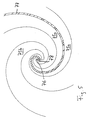
- Fig. 4 and Fig. 5 show a preferred embodiment of an antenna structure having a plate-shaped carrier 71 and on one side (without limiting the generality: the front) in spiral waveguide executed Spiralarm Modellen.
- stripline technique is meant that on the surface of the support structure (eg a plate) strip-shaped areas extending along the surface of the support consist of electrically conductive material, while other areas of the surface of the support are not covered with electrically conductive material are.
- the wearer may wear a layer of metal on its surface that is uniformly thick and extends over the entire surface at the front.
- To produce the stripline structure can then z. B. those areas that should be free of electrically conductive material to be demetallized, z. Using corrosive materials or by grinding and polishing.
- the electrically conductive regions can also be selectively applied locally.
- the carrier 71 is made of glass fiber reinforced epoxy resin, for example, as is common in printed circuit board technology for electrical and electronic circuits.
- the carrier may be made of any other dielectric material, e.g. As ceramic or mixed with ceramic powder polytetrafluoroethylene.
- the illustrated structure has an uninterrupted region 75 formed by the electrically conductive layer.
- the electrically conductive material-free areas have the shape of two spiral arms and are designated by the reference numerals 73, 74, wherein the areas 73, 74 in the center of the spiral by a transition region 76 are interconnected ( Fig. 5 ). Accordingly, complementary regions 75a, 75b, which are part of the region 75, extend to the regions 73, 74 as far as the center of the spiral, but are electrically separated from each other by the transition region 76.
- the spiral arms 75a, 75b are therefore electrically connected to each other only over the outer region of the region 75.
- a feed region 77 made of electrically conductive material.
- the supply area 77 is again a strip. This strip runs directly opposite one of the metallic spiral arms 75a or 75b, here opposite 75a.
- the strip 77 extends to the center of the spiral, but there it traverses the region immediately opposite the transition region 76 (FIG. Fig. 5 ).
- the strip 77 in the center is electrically connected to a connection 78 which extends through the material of the carrier 71 and electrically connects the strip 77 to the center-side end of the spiral arm 75b.
- the via 78 may be omitted and the strip 77 may instead continue to extend beyond the back of the transition region 76, following the back of the spiral arm 75b, but approximately at an extent corresponding to a 180 ° bend about the center of the spiral , end up.
- the width of the spiral arm 77 of the supply line changes in its course from the center of the spiral to the edge of the carrier 71, where he z. B. is electrically connected to the center conductors of coaxial cables 88a, 88b.
- the shield of the coaxial cable is in this case electrically connected to the electrically conductive region 75. Due to the stepwise changing width in the course of the spiral arm 77, an adaptation of the impedance to the desired connection value of the antenna structure is undertaken. For example, if a 50 ohm input is desired, but the impedance is 120 ohms without the adjustment, the stepwise change in width will result in the desired match.
- the adaptation can also be referred to as transformation of the impedance.
- the distance between the stages 79a, 79b (the distance is measured not linearly, but along the course of the spiral arm 77 along the curve) is chosen to be equal to a quarter of the wavelength of the center frequency of the frequency range , in which the antenna structure should work broadband.
- Z 2 denote the impedance which is to be transformed (without adaptation) and Z 1 the impedance to which it is to be adapted (desired connection value).
- Z T ⁇ 1 Z 1 ⁇ Z 2
- Z 1 3 50 ⁇ ⁇ ⁇ 120 50 3 ⁇ 66 .
- the spiral arm of the connecting line can also become continuously wider in its course from the center of the spiral to the outside. This also allows an adjustment of the impedance can be made.
- the antenna structure has a crossover (eg 72 in Fig. 4 ), which is preferably also applied in stripline technology on the same carrier carrying the actual antennas.
- the spiral arm 77 is connected at its view from the center of the spiral outer end to a so-designed crossover.
- the crossover is used to distribute frequency signals in different frequency ranges to two different or even more than two different connection lines.
- the connecting lines are each formed by a coaxial cable 88a, 88b, for example.
- two connection lines are present and divides the crossover signals in the range of the frequency band for Bluetooth of signals in the range of a GSM frequency band.
- the embodiment described here deviates from that described above with a single connection 64 between the antenna structure 63 and the hands-free device 54. Therefore, the connection line for the GSM frequency band can also be connected directly to the antenna line of the motor vehicle without reaching the hands-free device 54.
- the crossover 72 is preferably configured as a duplexer, d. H. it not only divides frequencies onto the connection lines which correspond to frequency signals received by the antenna structure, but also makes it possible to supply transmit signals via the connection lines so that they are emitted by the antenna structure. In this case, the crossover unit combines the signals that are fed via the different connection lines of the antenna structure. Also, the crossover can be used exclusively for the transmission mode.
- crossover network in stripline technology it is also possible to use commercially available, separate components which are fastened, for example, to the carrier of the antenna structure or which are fastened to another holder.
- the crossover z. B. be constructed from a suitable combination of bandpass filters.
- an amplifier is preferably provided which routes the signals on their way from the antenna structure to other devices such as an outdoor antenna of the motor vehicle or to the handsfree.
- Such an amplifier incorporated in the docking unit is therefore an optional but preferred feature of the invention.
- an amplifier may be provided (and part of the docking unit) which amplifies the transmission signals on their way to the antenna structure.
- a spiral antenna structure may also be constructed differently from that described with reference to FIG. 7 and be electrically connected. Examples are in the US 5,621,422 described. As explained therein, the existing two spiral arms can be electrically connected at their outer ends and are connected via a so-called 180 ° hybrid, which in turn allows the connection of connecting lines for signals in different frequency bands (as in US 5,621,422 shown in FIGS. 9 and 10 and described in the associated description in columns 10 and 11).
Landscapes
- Engineering & Computer Science (AREA)
- Mechanical Engineering (AREA)
- Telephone Set Structure (AREA)
Applications Claiming Priority (1)
| Application Number | Priority Date | Filing Date | Title |
|---|---|---|---|
| DE200710039879 DE102007039879A1 (de) | 2007-08-20 | 2007-08-20 | Anordnung zur Ankopplung und Aufnahme eines Mobiltelefons innerhalb eines Kraftfahrzeugs |
Publications (1)
| Publication Number | Publication Date |
|---|---|
| EP2028055A2 true EP2028055A2 (fr) | 2009-02-25 |
Family
ID=40111060
Family Applications (1)
| Application Number | Title | Priority Date | Filing Date |
|---|---|---|---|
| EP08075695A Withdrawn EP2028055A2 (fr) | 2007-08-20 | 2008-08-08 | Dispositif de couplage et de réception d'un téléphone mobile à l'intérieur d'un véhicule automobile |
Country Status (2)
| Country | Link |
|---|---|
| EP (1) | EP2028055A2 (fr) |
| DE (1) | DE102007039879A1 (fr) |
Cited By (2)
| Publication number | Priority date | Publication date | Assignee | Title |
|---|---|---|---|---|
| FR2944127A1 (fr) * | 2009-12-15 | 2010-10-08 | Continental Automotive France | Procede de communication entre un vehicule et un telephone portable pour effectuer un appel d'urgence |
| NL2033505B1 (en) * | 2022-11-11 | 2024-05-28 | Daf Trucks Nv | Vehicle comprising a storage assembly |
Families Citing this family (6)
| Publication number | Priority date | Publication date | Assignee | Title |
|---|---|---|---|---|
| DE102010054576B4 (de) * | 2010-12-15 | 2019-02-07 | Volkswagen Ag | Vorrichtung zur Kopplung eines mobilen Endgeräts mit einem Fahrzeug |
| DE102012112266B8 (de) * | 2012-12-14 | 2015-01-15 | Bury Sp.Z.O.O. | Koppelantennenanordnung und Aufnahmehalter einer Freisprecheinrichtung |
| DE102014221082A1 (de) * | 2014-10-16 | 2016-04-21 | Thomas Piper | Mobilfunkgerätebehälter und Verfahren zum Herstellen eines Mobilfunkgerätebehälters |
| DE102015004721A1 (de) * | 2015-04-09 | 2016-10-13 | Kathrein-Werke Kg | Kompensator |
| DE102015004722A1 (de) | 2015-04-09 | 2016-10-13 | Kathrein-Werke Kg | System zur drahtlosen Ankoppelung eines Mobilfunk-Endgerätes an eine externe Antennenstruktur |
| DE102016208164A1 (de) | 2016-05-12 | 2017-11-16 | Volkswagen Aktiengesellschaft | Vorrichtung zur Aufnahme eines Mobiltelefons |
Citations (2)
| Publication number | Priority date | Publication date | Assignee | Title |
|---|---|---|---|---|
| US5621422A (en) | 1994-08-22 | 1997-04-15 | Wang-Tripp Corporation | Spiral-mode microstrip (SMM) antennas and associated methods for exciting, extracting and multiplexing the various spiral modes |
| DE10313625A1 (de) | 2003-03-26 | 2004-10-07 | Siemens Ag | Aufnahmevorrichtung für ein Mobilfunkgerät |
Family Cites Families (2)
| Publication number | Priority date | Publication date | Assignee | Title |
|---|---|---|---|---|
| DE19925152A1 (de) * | 1999-06-02 | 2000-12-07 | Pro Elektronik Gmbh | Batteriebetriebene Freisprecheinrichtung |
| DE102006034128A1 (de) * | 2006-04-12 | 2007-10-18 | Funkwerk Dabendorf Gmbh | Anordnung zur Aufnahme eines Mobiltelefons innerhalb eines Kraftfahrzeugs |
-
2007
- 2007-08-20 DE DE200710039879 patent/DE102007039879A1/de not_active Ceased
-
2008
- 2008-08-08 EP EP08075695A patent/EP2028055A2/fr not_active Withdrawn
Patent Citations (2)
| Publication number | Priority date | Publication date | Assignee | Title |
|---|---|---|---|---|
| US5621422A (en) | 1994-08-22 | 1997-04-15 | Wang-Tripp Corporation | Spiral-mode microstrip (SMM) antennas and associated methods for exciting, extracting and multiplexing the various spiral modes |
| DE10313625A1 (de) | 2003-03-26 | 2004-10-07 | Siemens Ag | Aufnahmevorrichtung für ein Mobilfunkgerät |
Non-Patent Citations (1)
| Title |
|---|
| ZINKE, O.; BRUNSWIG, H.: "Lehrbuch der Hochfrequenztechnik", vol. 1, 1986, HEIDELBERG, pages: 97 |
Cited By (2)
| Publication number | Priority date | Publication date | Assignee | Title |
|---|---|---|---|---|
| FR2944127A1 (fr) * | 2009-12-15 | 2010-10-08 | Continental Automotive France | Procede de communication entre un vehicule et un telephone portable pour effectuer un appel d'urgence |
| NL2033505B1 (en) * | 2022-11-11 | 2024-05-28 | Daf Trucks Nv | Vehicle comprising a storage assembly |
Also Published As
| Publication number | Publication date |
|---|---|
| DE102007039879A1 (de) | 2009-03-05 |
Similar Documents
| Publication | Publication Date | Title |
|---|---|---|
| EP2011243B2 (fr) | Dispositif de couplage et de réception d'un téléphone mobile à l'intérieur d'un véhicule automobile | |
| EP2028055A2 (fr) | Dispositif de couplage et de réception d'un téléphone mobile à l'intérieur d'un véhicule automobile | |
| DE4494132B4 (de) | Funktelefongerät mit drahtlosem Kopfhörer | |
| DE19645259C2 (de) | Einrichtung für ein Mobilfunktelefon | |
| DE69412245T2 (de) | Freisprecheinrichtung für zellulartelefone zur verwendung in verbindung mit einem rundfunkempfänger in kraftfahrzeugen | |
| DE19830247A1 (de) | Mit Fahrzeug-Stereolautsprechern kombinierte integrierte Mobiltelephon-Freisprechanlage | |
| DE2813000A1 (de) | Guertel mit geraeten zum anhoeren von reproduzierter musik | |
| DE19840444A1 (de) | Kopfstütze, die mit mindestens einem Lautsprecher versehen ist, Fahrzeugsitz, der eine solche Kopfstütze umfasst, und Audioeinheit, die eine solche Kopfstütze einschließt | |
| EP0932524B1 (fr) | Recepteur radio | |
| DE4409382C2 (de) | Sendeempfangsgerät | |
| DE69900205T2 (de) | Mobiltelefon mit Freisprecheinrichtung | |
| EP1852978A2 (fr) | Dispositif de surveillance de signaux par une conduite d'antennes dans un poste d'abonné de radio mobile | |
| EP1737135A1 (fr) | Installation téléphonique pour automobile | |
| EP1727336A2 (fr) | Dispositif mains-libre pour un téléphone mobile comprenant un récepteur des message de circulation (TMC) | |
| DE10313625A1 (de) | Aufnahmevorrichtung für ein Mobilfunkgerät | |
| WO1998004051A1 (fr) | Dispositif de communication sans fil avec un telephone mobile | |
| DE60213611T2 (de) | Aufgeteilte Batterieversorgung | |
| DE102006058420B4 (de) | Mobiles Kommunikationsgerät mit internen Antennen | |
| DE19841847C2 (de) | Haltevorrichtung für Mobilfunktelefone | |
| DE10233444B4 (de) | Drahtloser Kopfhörer | |
| EP1622422A2 (fr) | Elément de prothèse auditive pour terminaux de communication mobile | |
| EP1755320B1 (fr) | Dispositif à mains-libres pour téléphone portable | |
| DE68919334T2 (de) | Zweiteiliges Funktelefon. | |
| DE29501275U1 (de) | Sende-/Empfangsanordnung für Mobilfunk | |
| DE29919581U1 (de) | Freisprecheinrichtung für Handys in Autos |
Legal Events
| Date | Code | Title | Description |
|---|---|---|---|
| PUAI | Public reference made under article 153(3) epc to a published international application that has entered the european phase |
Free format text: ORIGINAL CODE: 0009012 |
|
| AK | Designated contracting states |
Kind code of ref document: A2 Designated state(s): AT BE BG CH CY CZ DE DK EE ES FI FR GB GR HR HU IE IS IT LI LT LU LV MC MT NL NO PL PT RO SE SI SK TR |
|
| AX | Request for extension of the european patent |
Extension state: AL BA MK RS |
|
| STAA | Information on the status of an ep patent application or granted ep patent |
Free format text: STATUS: THE APPLICATION IS DEEMED TO BE WITHDRAWN |
|
| 18D | Application deemed to be withdrawn |
Effective date: 20110301 |