EP1853501B1 - Systeme de manipulation de plaque - Google Patents
Systeme de manipulation de plaque Download PDFInfo
- Publication number
- EP1853501B1 EP1853501B1 EP06735608A EP06735608A EP1853501B1 EP 1853501 B1 EP1853501 B1 EP 1853501B1 EP 06735608 A EP06735608 A EP 06735608A EP 06735608 A EP06735608 A EP 06735608A EP 1853501 B1 EP1853501 B1 EP 1853501B1
- Authority
- EP
- European Patent Office
- Prior art keywords
- plate
- picker
- picking
- stack
- slipsheet
- Prior art date
- Legal status (The legal status is an assumption and is not a legal conclusion. Google has not performed a legal analysis and makes no representation as to the accuracy of the status listed.)
- Expired - Lifetime
Links
Images





Classifications
-
- B—PERFORMING OPERATIONS; TRANSPORTING
- B65—CONVEYING; PACKING; STORING; HANDLING THIN OR FILAMENTARY MATERIAL
- B65H—HANDLING THIN OR FILAMENTARY MATERIAL, e.g. SHEETS, WEBS, CABLES
- B65H3/00—Separating articles from piles
- B65H3/44—Simultaneously, alternately, or selectively separating articles from two or more piles
-
- B—PERFORMING OPERATIONS; TRANSPORTING
- B65—CONVEYING; PACKING; STORING; HANDLING THIN OR FILAMENTARY MATERIAL
- B65H—HANDLING THIN OR FILAMENTARY MATERIAL, e.g. SHEETS, WEBS, CABLES
- B65H3/00—Separating articles from piles
- B65H3/08—Separating articles from piles using pneumatic force
- B65H3/0808—Suction grippers
- B65H3/0816—Suction grippers separating from the top of pile
-
- B—PERFORMING OPERATIONS; TRANSPORTING
- B65—CONVEYING; PACKING; STORING; HANDLING THIN OR FILAMENTARY MATERIAL
- B65H—HANDLING THIN OR FILAMENTARY MATERIAL, e.g. SHEETS, WEBS, CABLES
- B65H3/00—Separating articles from piles
- B65H3/24—Separating articles from piles by pushers engaging the edges of the articles
-
- B—PERFORMING OPERATIONS; TRANSPORTING
- B65—CONVEYING; PACKING; STORING; HANDLING THIN OR FILAMENTARY MATERIAL
- B65H—HANDLING THIN OR FILAMENTARY MATERIAL, e.g. SHEETS, WEBS, CABLES
- B65H9/00—Registering, e.g. orientating, articles; Devices therefor
- B65H9/08—Holding devices, e.g. finger, needle, suction, for retaining articles in registered position
-
- B—PERFORMING OPERATIONS; TRANSPORTING
- B65—CONVEYING; PACKING; STORING; HANDLING THIN OR FILAMENTARY MATERIAL
- B65H—HANDLING THIN OR FILAMENTARY MATERIAL, e.g. SHEETS, WEBS, CABLES
- B65H2406/00—Means using fluid
- B65H2406/30—Suction means
- B65H2406/34—Suction grippers
- B65H2406/342—Suction grippers being reciprocated in a rectilinear path
-
- B—PERFORMING OPERATIONS; TRANSPORTING
- B65—CONVEYING; PACKING; STORING; HANDLING THIN OR FILAMENTARY MATERIAL
- B65H—HANDLING THIN OR FILAMENTARY MATERIAL, e.g. SHEETS, WEBS, CABLES
- B65H2511/00—Dimensions; Position; Numbers; Identification; Occurrences
- B65H2511/20—Location in space
-
- B—PERFORMING OPERATIONS; TRANSPORTING
- B65—CONVEYING; PACKING; STORING; HANDLING THIN OR FILAMENTARY MATERIAL
- B65H—HANDLING THIN OR FILAMENTARY MATERIAL, e.g. SHEETS, WEBS, CABLES
- B65H2511/00—Dimensions; Position; Numbers; Identification; Occurrences
- B65H2511/50—Occurence
- B65H2511/51—Presence
- B65H2511/514—Particular portion of element
-
- B—PERFORMING OPERATIONS; TRANSPORTING
- B65—CONVEYING; PACKING; STORING; HANDLING THIN OR FILAMENTARY MATERIAL
- B65H—HANDLING THIN OR FILAMENTARY MATERIAL, e.g. SHEETS, WEBS, CABLES
- B65H2553/00—Sensing or detecting means
- B65H2553/80—Arangement of the sensing means
- B65H2553/81—Arangement of the sensing means on a movable element
-
- B—PERFORMING OPERATIONS; TRANSPORTING
- B65—CONVEYING; PACKING; STORING; HANDLING THIN OR FILAMENTARY MATERIAL
- B65H—HANDLING THIN OR FILAMENTARY MATERIAL, e.g. SHEETS, WEBS, CABLES
- B65H2701/00—Handled material; Storage means
- B65H2701/10—Handled articles or webs
- B65H2701/18—Form of handled article or web
- B65H2701/182—Piled package
- B65H2701/1826—Arrangement of sheets
- B65H2701/18264—Pile of alternate articles of different properties, e.g. pile of working sheets with intermediate sheet between each working sheet
-
- B—PERFORMING OPERATIONS; TRANSPORTING
- B65—CONVEYING; PACKING; STORING; HANDLING THIN OR FILAMENTARY MATERIAL
- B65H—HANDLING THIN OR FILAMENTARY MATERIAL, e.g. SHEETS, WEBS, CABLES
- B65H2701/00—Handled material; Storage means
- B65H2701/10—Handled articles or webs
- B65H2701/19—Specific article or web
- B65H2701/1928—Printing plate
Definitions
- This invention pertains to apparatus, systems and methods for handling plates in the context of a plate imaging system.
- the invention relates to the convenient storage of image-ready plates of a variety of sizes, delivery of a particular-sized plate from storage to an imaging system while disposing of an interleaf protective slipsheet.
- Imaging systems such as computer to plate (CTP) systems, are well known in the art. Imaging systems record an image on a film or plate. Plates are typically made of an aluminum substrate with a photosensitive emulsion applied to one surface. Plates of a variety of substrate and emulsion compositions are possible, including emulsions with a variety of imaging characteristics (e.g. exposure energy density, image working sense, and run length). Additionally, plate formats range to accommodate a variety of page (e.g. letter size) layouts. For example, plates sized to accommodate a single page up to a plate sized to accommodate thirty-two, sixty-four or more pages are known in the art. Thus, an imaging system can be called upon to process a wide variety plate types.
- CTP computer to plate
- a plate stack can be delivered on a pallet or other structure that provides support and simplifies conveyance.
- a plate stack can be delivered in a carton or other protective enclosure. Larger sized plates are difficult to transport and store because of their size, weight and susceptibility to damage.
- imaging systems provide integrated storage facilities for a quantity of plates that are likely to be used and automated mechanisms for selecting and transporting a plate to be imaged.
- Prior art imaging systems have incorporated integrated storage of plate stacks.
- Imaging system cassettes, trays, bays or other mechanisms have traditionally been used to constrain the orientation of loaded plates so that plate picking and transport can be reliably accomplished.
- Storage areas typically contain one or more plate edge stops, guides or other mechanical devices to constrain the loaded plate orientation.
- a plate bay housing a carton of plates stacked horizontally and resting on one edge, comprises a stop (bay floor) for supporting one end of the carton which constrains the horizontal plate stack in one dimension.
- a plate cassette will typically have at least two stops for adjacent plate edges to constrain the plate stack orientation in two dimensions. Manual loading of a significant quantity of plates into an imaging system storage facility that restricts placement may thus be a time consuming process.
- Slipsheets tend to be attracted to either the plate picked for imaging or to the plate remaining on the top of a plate stack.
- Slipsheets are typically made of a flimsy and slippery material and so are easily damaged or can become misaligned with an adjacent plate. These characteristics make locating, obtaining and transporting a slipsheet challenging. Additionally, if a slipsheet becomes creased or folded, it can damage the emulsion on the plate it is protecting if it is subsequently dragged across the emulsion surface.
- An additional object of the present invention is to dispose of slipsheets internal to the plate handling system by stacking them vertically. This minimizes storage space, simplifies unloading and transport for final disposal, and presents an opportunity for reuse of the slipsheets.
- Document EP 1 428 778 discloses a suction mechanism allowing both a plate and an interleaf to be picked simultaneously.
- the present invention provides plate handling systems apparatus and methods as defined by the claims.
- the plate handling system to be used in conjunction with an imaging system, enables a significant period of unattended imaging system operation while requiring limited floor space by arranging plate storage areas in a vertical fashion with elevating pick and transport mechanisms. Plates, organized in stacks, can be easily loaded into the plate handling system by one person. Interleaf slipsheets are obtained and are stacked with a flat profile in an internal storage area to minimize storage requirements, increase reliability, protect plate surfaces and enable slipsheet reuse.
- the invention can be adapted to imaging systems of a variety of types and sizes but is particularly well suited to imaging systems that image plates of a very large size.
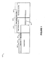
- FIG. 1 depicts a plate handling system (PHS) 110 connected with an imaging system (IS) 102.
- PHS 110 is configured to:
- PHS 110 comprises a plate storage unit (PSU) 112 and a plate transport unit (PTU) 114.
- PHS 110 can obtain power, compressed air and other operating requirements directly from an external source or from IS 102.
- PHS 110 can include one or more controllers operative to determine the state of various components and contents of PHS 110, to control the operation of various actuating components of PHS 110, to communicate with IS 102 controller, and to provide a user with one or more status indicators and operational controls.
- an IS 102 controller or another system connected to both PHS 110 and IS 102 may perform one or more PHS 110 control functions remotely.
- PTU 114 is located horizontally adjacent to one side of IS 102 and is of a height enabling it to both access all plates within PSU 112 and transport a plate along a plate path 120 (one possible path shown) to a plate inlet 104 (e.g. a load table).
- PTU 114 can fasten to IS 102 with removable fasteners to facilitate modular installation and to ensure their alignment during operation. Removable power, air, communication and other connections can be made between the two units.
- PTU 114 is enclosed in a protective cover with permanent openings for plate transport and removable covers for maintenance access.
- PTU 114 comprises a horizontally mounted plate transporter, which transports a picked plate from PSU 112, first horizontally to a supporting platform within the plate transporter and then vertically to a plate inlet 104 at which point IS 102 completes the horizontal transport into the IS 102.
- the plate transporter is preferably mounted on an elevating structure to enable it to pick up and transfer a plate from any number of vertical positions in PSU 112 and IS 102, respectively.
- the plate During transport, the plate has a horizontal orientation on the supporting platform with the plate edge, proximal to plate inlet 104, oriented approximately perpendicular to the direction of horizontal motion.
- the emulsion side of the plate is preferably oriented on top but can be reversed if necessary.
- PTU 114 mechanisms and orientations are also possible.
- the plate transporter can be inclined.
- PTU 114 can include a plate rotation unit to change direction of movement or to establish an alternate horizontal orientation, independent of plate orientation in PSU 112.
- PTU 114 can include a plate-flipping unit to change the emulsion side orientation.
- PTU 114 also comprises a horizontally mounted slipsheet transporter, which transports a picked slipsheet along a slipsheet path 130 (one possible path shown). Transport occurs first horizontally from the PSU 112 onto a supporting structure within the slipsheet transporter and then down to a slipsheet storage area located near the bottom of the PTU 114 housing where it released for subsequent disposal.
- the slipsheet transporter is preferably located directly below the plate transporter and mounted on the same elevating structure.
- the sheet storage facility is sized to hold approximately 1000 slipsheets in a vertically stacked arrangement.
- a removable cover allows access to the storage unit so that slipsheets may be discarded.
- PSU 112 is located horizontally adjacent to one side of PTU 114 and fastened to PTU 114 with removable fasteners to facilitate modular installation and alignment during operation. Removable power, air, communication and other connections can be made between the two units. PSU 112 is enclosed in a protective cover.
- PSU 112 includes a predetermined number of adjustable-height, storage shelves.
- Each shelf demarcates the bottom of a plate storage area, suited for storing a plurality of horizontally oriented plates and protective interleaf slipsheets stacked on a pallet or other suitable supporting conveyance structure.
- each shelf is approximately rectangular, consistent with the enclosure, and all corresponding plate storage areas are accessible through a permanent opening one the side proximal to PTU 114. All plate storage areas are accessible through at least one removable cover on one of the other sides to allow horizontal access for loading and unloading a pallet.
- All plate storage areas are accessible through a second permanent opening on one of the other sides, but in a preferred embodiment, on the side distal to PTU 114, to allow access by a plate picker.
- the remaining side is either permanently covered or has a removable cover for maintenance access.
- PSU 112 also comprises a plate picker capable of lifting two adjacent corners of the top plate of a stack of plates.
- the plate picker also includes a capability to pick and hold the slipsheet located directly below the picked plate.
- the plate picker is dynamically mounted to an elevating structure capable of precisely positioning the plate picker at the top of any plate stack.
- the plate picker mounting facilities on the elevating structure are movable in a horizontal direction to enable the plate picker to reach into a shelf area to pick a plate or to withdraw from the shelf area to permit elevation.
- the plate picker pulls the held slipsheet away from the plate stack for disposal externally or in an alternative slipsheet storage area.
- the plate picker could be a modular unit that is fastened to PSU 112.
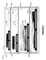
- FIG. 2 is a side view of PSU 112 according to one embodiment of the invention. It depicts a view of PSU 112, without its protective covering, from the side where pallets are loaded and unloaded. For clarity, the plate picker and associated moving structures are not shown.
- Vertical members 202 and horizontal members 204 provide structural support for PSU 112.
- Vertical members 202 contain a plurality of shelf mounting facilities 206 (e.g. threaded holes), each with a consistent vertical spacing such that a shelf 210 may be mounted in any number of vertical positions.
- a predetermined number of shelves 210A-210D, mounted in exemplary positions, are depicted for a variety of exemplary plate pallets 230 and vertical plate (with interleaf slipsheet) stacks 240.
- Configuration of shelves 210 is performed either during construction of PSU 112 or at a customer site.
- Exemplary plate storage areas 220A-220D are depicted.
- shelves 210 can be equipped with an extendable table to allow plates to be stacked by hand or to be lowered by a mechanism such as a crane.
- Plate stacks 240 are loaded proximal to the transport side of PSU 112 (the side adjacent PTU 114). Plate stacks 240 can have a variety of sizes, constrained only by the limitations of IS 102 and PHS 110. A plate stack 240 should nominally be loaded with its nearest side approximately parallel with the transport side of PSU 112. Some rotational variance is permitted as will be described later. Plate stacks 240 should be loaded with a plate setback 260 from the transport side. PTU 114 establishes a maximum value for plate setback 260 to ensure accessibility. In one embodiment, the maximum plate setback 260 is configured to be less than eight inches. Plate storage areas 220C and 220D are depicted as having adequate room for alternative slipsheet storage areas 250A and 250B, based on the size of loaded plates.
- FIG. 3 is a perspective view of PHS 110 depicting main operational elements according to one embodiment of the invention. For clarity, portions of the enclosing covers, supporting structures and other details are not depicted.
- FIG. 3 depicts PSU 112 as including a picker elevator 302, comprising three horizontal support members positioned outside the vertical support members 202 of PSU 112.
- Picker elevator 302 is suspended by a set of attached suspension mountings (not shown), which are flexibly coupled to vertical movement members, such as guides or leadscrews (not shown), which are in turn fastened to support members of PSU 112.
- Picker elevator 302 vertical motion can be accomplished by a variety of means.
- one or more motors, each coupled with a leadscrew, pulley mechanism, or other linear motion system can be employed to move picker elevator 302 vertically.
- Picker elevator 302 also includes a plate picker shelf 304, which is fastened to the supporting members of picker elevator 302. While picker elevator 302 is moving between plate storage shelves 210, plate picker 310 is parked on plate picker shelf 304 so that plate picker 310 does not impinge a shelf support member 305.
- Picker elevator 302 also includes plate picker mounts 306, flexibly coupled to horizontal movement members, such as guides or leadscrews (not shown), which are in turn fastened to picker elevator 302 support members. Each plate picker mount 306 can move independently towards (and away from) PTU 114. Plate picker mount 306 motion can be accomplished by a variety of means.
- a motor coupled to a leadscrew, pulley system or other linear motion system can be employed to move each plate picker mount.
- the controller for picker elevator 302 can be configured to postpone vertical motion while plates are being loaded in a plate storage area. This enables an operator to load plates in one plate storage area 220 while PHS 120 is picking or transporting plates from a different plate storage area 220.
- Plate picker 310 is fastened to each plate picker mount 306 by means of a retractable fastener 308.
- a retractable fastener 308 can comprise a pair of solenoid driven pins.
- One retractable fastener 308 is positioned at each longitudinal end of plate picker 310.
- plate picker 310 Before releasing a retractable fastener 308, plate picker 310 must be moved so that it is positioned over plate picker shelf 304. Once, retracted plate picker 310 is parked on plate picker shelf 304 and can be moved vertically without impinging shelf support members 305.
- retractable fasteners 308 are extended to rigidly couple plate picker 310 with both plate picker mounts 306. Since, plate picker mounts 306 can move independently, one or both of the plate picker mounts 306 or the retractable fasteners 308 are configured to provide some degree of rotational freedom.
- Plate picker 310 comprises at least one picker element 312 capable of lifting a portion of the top plate from a plate stack 240. Picker element 312 also obtains and holds a portion of the corresponding slipsheet protecting the plate immediately below the top plate.
- two picker elements 312 are configured so that picker elements lift adjacent corners of a plate on the side distal to PTU 114. Each picker element 312 moves independently along the longitudinal axis of plate picker 310 to position at a respective plate corner.
- plate picking rotational freedom can also be obtained by configuring picker elements 312 with the ability to independently move in a direction perpendicular to the axis of plate picker 310 (e.g. plate path 120 direction).
- Each picking element 312 is fastened to a separate picker element mount (not shown), which is flexibly coupled to a horizontal movement member that are aligned with longitudinal axis of plate picker 310.
- a horizontal movement member such as a guide or leadscrew (not shown), is in turn fastened to plate picker 310.
- Each picker element mount can move independently. Mount motion can be accomplished by a variety of means. For example, a motor coupled to a leadscrew, pulley system or other linear motion system can be employed to move each picker element mount.
- FIG. 3 depicts PTU 114 as including vertical support members 324, horizontal support members 326, protective cover 320 (partially shown), and a plate outlet 322 corresponding to plate inlet 104. It also depicts an elevating transporter 330 and a slipsheet storage area 350 (e.g. removable pallet or tray). Transporter 330 depicts an integrated unit providing both picked plate and slipsheet transport capabilities within one elevating structure. Implementation of the elevating structure can be accomplished in a manner similar to that describe above for picker elevator 302.
- Transporter 330 is comprised of a horizontal support structure 332 for supporting and transporting a picked plate.
- Support structure 332 is configured with two or more slots 334 positioned longitudinally between PSU 112 and plate outlet 322.
- Each slot 334 provides an opening through support structure 332 from the top to bottom surface.
- Each slot 334 extends to approximately each longitudinal end of support structure 332.
- a movable vacuum bar system (not shown) is mounted transversely to slots 334.
- Plate suction cups 336 are mounted to the movable vacuum bar, and protrude through slots 334. Plate suction cups 336 are vertically positioned in approximate alignment with the top surface of support structure 332, so that a picked plate is both supported with a substantially flat profile and is firmly held on the non-emulsion side during transport.
- the movable vacuum bar system can be moved by a linear motion system similar to those described above for plate picker mount 306.
- Plate suction cups 336 can thus be moved together approximately the full length of slots 334.
- Detailed plate transport operation is described below.
- the structure of slipsheet transport mechanisms and their operation is also described below.
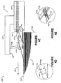
- Figures 4A-4E are perspective and side views illustrating plate picking according to one embodiment of the invention.
- Figure 4A is a perspective view of PSU 112 during an exemplary plate picking operation of a plate from the top shelf.
- Picker elevator 302 ascended to enable access to plate stack 240D located on shelf 210D.
- Plate picker 310 moved to a first pick position (as shown) for plate stack 240D from its parked position on plate picker shelf 304. In the first pick position, plate picker 310 is ready to pick the top plate.
- plate stack 240D was loaded such that the plate stack is rotated with a small clockwise rotation relative to PSU 112.
- Plate picker 310 moved at high speed to an estimated plate stack position, based on information configured about the plate stack and information from the last pick from this stack. Plate picker 310 then moved at low speed until it was in a first pick position.
- Umbilical arm 402, or other flexible cabling mechanism provides for compressed air, vacuum, electrical and other connections to couple plate picker 310 with fixed receptacles on plate picker shelf 304. Flexible cabling (not shown) from plate picker shelf 304 to fixed terminations in PSU 112 complete the connections.
- Plate stack 240 rotational variations from an intended orientation of at least ten millimeters for picking edge (edge proximal to plate picker 310) corner positions is desirable to simplify loading.
- one corner of the picking edge can have a position that is ten millimeters different in the plate path direction than the other picking corner.
- Positional variations of at least 10 millimeters, laterally, from an intended position the top plate can be desirable to simplify loading.
- Many references can be used for determining plate position.
- One exemplary reference is the center point of the picking edge. Practically, moving or loading a pallet of plates, without some holding mechanism may cause plates to shift so that their edges are not aligned. Thus, even accurate positioning of pallet 230 may cause at least some plates in plate stack 240 to rotate or shift position.
- positional variations of up to 50 millimeters and rotational variations of up to 30 millimeters from an intended placement can be accommodated.
- An intended placement can be determined by a number of methods.
- One exemplary method is for PHS 110 to specify the intended placement and for the user to attempt to load plate stack 240 close to the intended placement.
- Another exemplary method is for the user to load plate stack 240 with an arbitrary position and provide PHS 110 with information about the plate stack to enable PHS 110 to estimate plate stack 240 position.
- the user could provide PHS 110 with an approximate measured position of plate stack 240, an approximate measured height of plate stack 240 or pallet 230, as well as dimensions for and a quantity of plates in plate stack 240.
- PHS 110 can then estimate plate stack 240 position and elevation and estimate how to position plate picker 310 on approach to the picking edge of the top plate.
- plate picker 310 approached plate stack 240D at low speed
- horizontal and vertical sensors mounted, for example, on each picker element 312, detected the top and proximal edges of plate stack 240D respectively.
- Picker elevator 302 moved to position both picker elements 312 at the top of plate stack 240D.
- Plate picker mounts 306 moved independently to position each picker element 312 at their initial proximal edge position. Then, each picker element 312 moved transversely to position themselves at their corresponding plate stack 240D corners.
- Plate picker mounts 306 moved independently to maintain picker elements 312 in position at the proximal edge while moving to the corners. In the resulting first pick position; plate picker 310 longitudinal axis is approximately parallel to the proximal edge of plate stack 240. During subsequent plate picking movements, this alignment is preserved.
- Figure 4B is a side view of plate picker 310 in a second pick position corresponding to two top plate corners lifted and the interleaf slipsheet held.
- Figure 4C is an expanded side view of plate picker 310 in a second pick position.
- Plate picker 310 comprises a plate picker bar 430 that extends between plate picker mounts 306 (not shown).
- One picker element 312 is depicted, which comprises, according to a preferred embodiment:
- Picker arm 432 includes a vertical sensor 442, such as an electro-optic sensor, mounted at the leading edge the arm. It also includes a plate lifter 434, which is attached to picker arm 432 by coupling 436.
- plate lifter 434 is a plate cup, which blows air onto the top surface of a plate to lift the plate, without making contact, according to the Bernoulli principle.
- a suction cup can be used to lift the plate.
- Slipsheet 420A and 420B correspond to one slipsheet 420, located directly below picked plate 410, in one of two exemplary positions.
- Slipsheet 420A corresponds to slipsheet 420 being attracted, by static or other weak forces, to picked plate 410.
- Slipsheet 420B corresponds to slipsheet 420 being attracted, by static or other weak forces, to plate stack 240.
- slipsheet shoe 438 (shown in a perspective view in figure 4D ) attracts and holds slipsheet 420.
- holes 470 located on both top and bottom surfaces of slipsheet shoe 438, attract slipsheet 420 using a vacuum.
- slipsheet 420 is pierced by pins 480, located on both top and bottom surfaces of slipsheet shoe 438, which limit lateral slipsheet movement.
- pins 480 located on both top and bottom surfaces of slipsheet shoe 438, which limit lateral slipsheet movement.
- Different mechanisms for attracting and holding a slipsheet can be substituted in other embodiments of the invention. For example, once attracted a mechanical clamp or high friction shoe surface can aid in holding slipsheet 420.
- both picker elements 312 are in the second pick position, they are actuated to achieve a third pick position.
- the third pick position (depicted in figure 4E ) corresponds to picked plate 410 moved in the plate path 120 direction while slipsheet 420 is held fast. This is accomplished by first extending plate pusher 440, using a linear motion system, with limited force until the proximal edge 450 of picked plate 410 is contacted.
- the axis of plate pusher 440 is preferably offset towards the center of picked plate 410 and parallel with the longitudinal axis of picker arm 432.
- plate lifters 434 release picked plate while plate pushers 440 move in a coordinated fashion to a fully extended position using higher force so that the distal end of picked plate 410 extends into PTU 114.
- Different mechanisms for moving picked plate into PTU 114 can be substituted in other embodiments of the invention. For example, extendable arms that hook over the top of the lifted plate corners can pull picked plate.
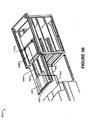
- Figure 5A is a perspective view of plate picker 310 transferring a picked plate (depicted with partial transparency for clarity) to transporter 330 according to one embodiment of the invention. For clarity, some aspects of PSU 112 and PTU 114 are not illustrated.
- the third pick position is depicted. Before progressing to the third pick position, transporter 330 must be moved into position to receive picked plate 410. First, transporter 330 ascended to a height where the top surface of support structure 332 is approximately aligned with the top surface of plate stack 240D. This positioning can be based on information used to position plate picker 310 or can be performed independently by information obtained from a plate sensor mounted on transporter 330.
- plate suction cups 336 moved to a pick up position located at the end, proximal to PSU 112, of slots 334.
- Picked plate 410 when moved into PTU 114 (as shown), is positioned directly above plate suction cups 336.
- suction is applied so that picked plate 410 is firmly grasped on its bottom surface.
- plate suction cups move in the direction of plate path 120, pulling picked plate 410 out of PSU 112 until it is completely supported by support structure 332.
- Different horizontal transporting mechanisms can be substituted in other embodiments of the invention. For example, a picked plate can be moved partway onto a conveyor belt support structure, which then pulls the picked plate into PTU 114.
- support structure 332 can be mounted on a turntable, which allows the plate path 120 to be altered, for example perpendicularly. This can facilitate an advantageous footprint for IS 102 and PHS 110.
- support structure 332 can include a turntable mounted in the top surface of the structure to allow picked plate 410 to be rotated by ninety degrees to facilitate a preferred load orientation in IS 102.
- support structure 332 can include a plate alignment mechanism to correct any small rotational misalignment caused by loading or picking plates.
- plate picker 310 can be retracted to either begin picking another plate from plate stack 240D or it can be parked on plate picker shelf 304 and elevated to the next plate stack 240.
- slipsheet shoe 438 Before moving, however, slipsheet shoe 438 must release slipsheet 420. This can be accomplished, for example, by briefly changing airflow direction in holes 470 so that slipsheet 420 is blown off pins 480.
- pins 480 can be fastened to slipsheet shoe 438 by pivoting fasteners, which pivot on an axis that is horizontally transverse to plate path 120. Pivoting can be controlled by, for example, a solenoid.
- pins 480 are pivoted in the direction of plate path 120 so that the slipsheet slides off the pins.
- Figure 5B is a perspective view of PTU 114 transferring a plate a picked plate to IS 102 according to one embodiment of the invention.
- the figure depicts transporter 330 at the plate pick up elevation with picked plate 410 in the completely supported position, having traversed plate path 120A.
- transporter 330 moves picked plate 410 along plate path 120B to plate inlet 104 (not shown) height.
- picked plate is moved into plate inlet 102 where IS 104 pulls it along the remainder of plate path 120C.
- the initial movement along plate path 120C can be accomplished, for example, by turning off the vacuum on plate suction cups 336, moving them partway towards PSU 112, reapplying vacuum and moving plate suction cups 336 back towards IS 102. Different movement mechanisms can be substituted in other embodiments of the invention.
- the final movement along plate path 120C is accomplished by IS 102.
- FIG. 6 is a side view of PHS 110 illustrating slipsheet disposal according to one embodiment of the invention.
- Transporter 330 is depicted in two positions. In the first position, transporter 330A is ready to pick up slipsheet 420 from plate stack 240D.
- Transporter 330 includes a slipsheet transporter 602, which reaches into PSU 112 to obtain slipsheet 420 (depicted as 420A when positioned on the plate stack).
- a vacuum bar accomplishes this.
- the vacuum bar 606 is located inside slipsheet transporter 602 and can move along a track 604 which is capable of extending partway into PSU 112. Vacuum is supplied to vacuum bar 606 by a hose in a flexible cable track or by other similar methods. Vacuum bar 606 has openings on its bottom surface that attract and hold slipsheet 420.
- vacuum bar 606 and track 604 is extended by a motorized leadscrew or other linear motion system for example, so that vacuum bar 606 is positioned (606A) directly above slipsheet 420A.
- An electro-optic sensor for example, can be used to determine the correct position above slipsheet 420SA.
- vacuum bar 606 can be coupled to the lower side of the plate vacuum bar system. In this case, transporter 330 may need to elevate to a new position to allow access to slipsheet 420A.
- slipsheet 420 is positioned (420B) inside slipsheet transporter 602 and is partially supported by a sectional platform 610 positioned in a support position (610A).
- Sectional platform 610 can comprise a series of lightweight bars flexibly attached to each other at their extremities and supported by wheels or other low-friction supports that can travel along oval track 612. Vacuum bar 606B continues to hold slipsheet 420B in position.
- transporter 330 descends along slipsheet path 130B to a point just above slipsheet storage area 350. This position is depicted as transporter 330B.
- platform 610 is moved, by a motorized pulley system for example, along oval track 612 to a release position (610B). As platform 610 moves and removes support, slipsheet 410 falls with an approximately flat profile on top of previously deposited slipsheets in slipsheet storage area 350. Finally, vacuum is removed and vacuum bar 606 releases the edge of slipsheet 410, allowing it to fall and lie flat on top of the slipsheet stack. Deposited slipsheets can be subsequently removed from slipsheet storage area 350.
- FIG. 7 is a side view of a PHS 110 illustrating slipsheet disposal according to another embodiment of the invention.
- This embodiment is possible when alternative slipsheet storage area 250 occupies at least half the corresponding plate storage area 220.
- Plate picker 310 and slipsheet 420 are illustrated in two positions. In the first position, plate picker 310A is holding slipsheet 420A, with a picked plate having just transferred to PTU 114. Plate picker 310 then moves towards its parked position, pulling slipsheet 420 with it. When plate picker 310 reaches a position (310B), near its parked position, it releases slipsheet 420B. The edge of slipsheet 420B falls to storage shelf 210, coming to rest with an approximately flat profile.
Landscapes
- Engineering & Computer Science (AREA)
- Mechanical Engineering (AREA)
- Sheets, Magazines, And Separation Thereof (AREA)
Claims (18)
- Procédé pour manipuler des plaques d'impression avant leur exposition par un système de formation d'image, le procédé comprenant les étapes de :chargement d'une pile de plaques contenues dans une zone de stockage (112) d'un système de manipulation de plaques (110) vers un emplacement prévu ;obtention d'informations relatives à la pile de plaques avant de prélever une ou plusieurs plaques ;alignement d'un dispositif de prélèvement de plaques (302) du système de manipulation de plaques (110) avec la position et la rotation réelles du bord de préhension de la plaque supérieure de la pile de plaques ; dans lequel la plaque a un bord de préhension ayant deux coins, dans lequel la position et la rotation réelles du bord de préhension peuvent différer de la position et de la rotation prévues du bord de préhension correspondant au positionnement prévu de la pile de plaques, et dans lequel ladite étape d'alignement comprend les étapes d'alignement du dispositif de prélèvement de plaques (302) verticalement avec la plaque supérieure de la pile de plaques sur la base des informations concernant la pile de plaques, le déplacement du dispositif de prélèvement de plaques (302) vers le bord de préhension de la plaque supérieure sur la base des informations concernant la pile de plaques, la détection de la position et de la rotation du bord de préhension de la plaque supérieure et le déplacement du dispositif de prélèvement de plaques (302) dans une orientation de préhension alignée avec la position et la rotation détectées du bord de préhension de la plaque supérieure ;prélèvement de la plaque supérieure de la pile de plaques ;déplacement de la plaque prélevée dans une direction de trajectoire de plaque jusqu'à une position de transport ; ettransport de la plaque prélevée de la position de transport jusqu'au système de formation d'image en vue de son exposition.
- Procédé selon la revendication 1, dans lequel les informations concernant la pile de plaques comprennent aussi :une position estimée du bord de préhension de la plaque supérieure de la pile de plaques.
- Procédé selon la revendication 2, dans lequel les informations concernant la pile de plaques comprennent :les dimensions de la pile de plaques, la quantité de plaques contenue dans la pile de plaques et les dimensions d'une plaque.
- Procédé selon la revendication 3 pour un système de manipulation dans lequel le dispositif de prélèvement de plaques comprend une barre de préhension (430) normalement disposée perpendiculairement à la direction de trajectoire de plaque et une paire d'éléments préhenseurs (312) montés sur la barre de préhension et capables de se déplacer individuellement le long de la barre de préhension, et un détecteur de plaque (444) couplé à chaque élément préhenseur pour détecter une plaque,
le procédé comprenant : le déplacement du dispositif de prélèvement de plaques vers le bord de préhension de la plaque supérieure sur la base des informations concernant la pile de plaques :le déplacement de la barre de préhension de plaque (430) le long de la direction de trajectoire de plaque jusqu'à la position estimée du bord de préhension de la plaque supérieure ; etle déplacement des éléments préhenseurs (312) le long de la barre de préhension jusqu'aux positions estimées d'un ou plusieurs coins du bord de préhension sur la base de la position estimée du bord de préhension et des dimensions de la plaque. - Procédé selon la revendication 4, dans lequel la détection de la position et de la rotation du bord de préhension de la plaque supérieure comprend le déplacement de la barre de préhension (430) et des éléments préhenseurs (312) de manière à positionner les détecteurs afin de détecter les positions du ou des coins du bord de préhension de la plaque supérieure.
- Procédé selon la revendication 5, dans lequel le déplacement du dispositif de prélèvement de plaques dans une orientation de prélèvement qui est alignée avec la position et la rotation détectées du bord de préhension de la plaque supérieure comprend le déplacement de la barre de préhension et des éléments préhenseurs de manière à aligner les éléments préhenseurs avec les positions détectées du ou des coins du bord de préhension de la plaque supérieure.
- Procédé selon la revendication 1, dans lequel le prélèvement de la plaque supérieure de la pile de plaques comprend :le soulèvement de chaque coin du bord de préhension de la plaque supérieure ;l'attraction d'une feuille intercalaire (420, 420A, 420B) à partir de l'espace situé au-dessous de chaque coin soulevé où la feuille intercalaire adhère soit à la face inférieure de la plaque supérieure soit à la face supérieure de la pile de plaques ; etle maintien de la feuille intercalaire attirée.
- Procédé selon la revendication 7 dans lequel le dispositif de prélèvement de plaques comprend une barre de préhension (430) normalement disposée perpendiculairement à la direction de trajectoire de plaque et une paire d'éléments préhenseurs (312) montés sur la barre de préhension et capables de se déplacer individuellement le long de la barre de préhension, chaque élément préhenseur comprenant :une coupelle pour plaque suspendue à un bras préhenseur pour soulever le coin de la plaque supérieure sans entrer en contact avec la plaque ;un sabot pour feuille intercalaire comprenant des orifices d'aspiration sur les faces supérieure et inférieure pour attirer la feuille intercalaire ; etun pousseur de plaque permettant d'entrer en prise avec une portion soulevée du bord de préhension de la plaque supérieure.
- Procédé selon la revendication 8, dans lequel le soulèvement du coin du bord de préhension de la plaque supérieure comprend le soufflage d'air à travers la coupelle pour plaque (434) pour créer une zone de basse pression permettant de soulever le coin de la plaque.
- Procédé selon la revendication 8, dans lequel l'attraction de la feuille intercalaire à partir de l'espace situé sous chaque coin soulevé comprend :le déplacement du sabot pour feuille intercalaire (438) dans l'espace situé sous le coin soulevé ; etl'application d'un vide au sabot pour feuille intercalaire (438) pour attirer la feuille intercalaire vers un orifice d'aspiration.
- Procédé selon la revendication 10, dans lequel le maintien de la feuille intercalaire attirée comprend le maintien du vide appliqué au sabot pour feuille intercalaire (438).
- Procédé selon la revendication 8, dans lequel le pousseur de plaque (440) est capable de se déplacer le long de la direction de transport de plaque et le déplacement de la plaque prélevée dans la direction de trajectoire de plaque jusqu'à une position de transport comprend le déplacement du pousseur de plaque pour déplacer la plaque supérieure le long de la position de trajectoire de plaque dans la position de transport de plaque.
- Système de manipulation de plaques permettant d'alimenter un système de formation d'image en plaques, le système comprenant :une installation de stockage de plaques comprenant au moins une zone de stockage (112) ayant une plaque avec un positionnement de stockage réel dans une position et une rotation réelles, dans lequel le positionnement de stockage réel peut être différent du positionnement prévu de la plaque ;un contrôleur permettant de commander l'opération de manipulation de la plaque ;un dispositif de prélèvement de plaques (310) permettant de prélever la plaque, dans lequel le contrôleur est capable de déterminer automatiquement la position et la rotation réelles de la plaque et d'aligner le dispositif de prélèvement de plaques avec la position et la rotation réelles de la plaque avant de la prélever ; etun transporteur de plaques permettant de transporter la plaque jusqu'au système de formation d'image en vue de son exposition.
- Système de manipulation de plaques selon la revendication 13, le système comprenant aussi :l'installation de stockage de plaques comprend une pile de plaques ayant un positionnement réel qui peut différer du positionnement prévu et dans lequel une plaque de la pile de plaques chargée comprend une plaque ayant un bord de préhension ayant deux coins et une position réelle et une rotation réelle, où la position et la rotation réelles du bord de préhension diffèrent d'une position et d'une rotation prévues du bord de préhension correspondant au positionnement prévu de la pile de plaques ;le dispositif de prélèvement de plaques pour prélever la plaque supérieure de la pile de plaques, dans lequel le contrôleur est capable de déterminer automatiquement la position et la rotation réelles de la plaque supérieure de la pile de plaques et d'aligner le dispositif de prélèvement de plaques avec la position et la rotation réelles de la plaque supérieure avant de la prélever ; etle transporteur de plaques permettant de transporter la plaque prélevée jusqu'au système de formation d'image en vue de son exposition.
- Système de manipulation de plaques selon la revendication 13, dans lequel le dispositif de prélèvement de plaques comprend :une barre de préhension (430) normalement disposée perpendiculairement à la direction de trajectoire de plaque et capable de se déplacer le long d'une direction de trajectoire de plaque ;une paire d'éléments préhenseurs (312) montés sur la barre de préhension et capables de se déplacer individuellement le long de la barre de préhension ; etun détecteur de plaque couplé à chaque élément préhenseur pour détecter une plaque.
- Système de manipulation de plaques selon la revendication 15, dans lequel le contrôleur est capable de :obtenir des informations sur une pile de plaques contenant la plaque ;déplacer le dispositif de prélèvement de plaques verticalement pour l'aligner avec la plaque supérieure de la pile de plaques sur la base des informations concernant la pile de plaques ;déplacer le dispositif de prélèvement de plaques vers le bord de préhension de la plaque supérieure sur la base des informations concernant la pile de plaques :déplacer la barre de préhension et les éléments préhenseurs de manière à positionner les détecteurs afin qu'ils détectent les positions d'un ou plusieurs coins du bord de préhension de la plaque supérieure ;obtenir une position et une rotation détectées du bord de préhension de la plaque supérieure de la pile de plaques ;déplacer le dispositif de prélèvement de plaques dans une orientation de prélèvement alignée avec la position et la rotation détectées du bord de préhension de la plaque supérieure ;actionner le dispositif de prélèvement de plaques pour qu'il prélève la plaque supérieure de la pile de plaques ; etactionner le transporteur de plaques pour qu'il transporte la plaque prélevée jusqu'au système de formation d'image.
- Système de manipulation de plaques selon la revendication 15, dans lequel le dispositif de prélèvement de plaques est également capable de déplacer la plaque prélevée dans la direction de trajectoire de plaque jusqu'à une position de transport et dans lequel le transporteur de plaques est capable de transporter la plaque prélevée de la position de transport jusqu'au système de formation d'image.
- Système de manipulation de plaques selon la revendication 17, dans lequel le contrôleur est également capable d'actionner le dispositif de prélèvement de plaques pour qu'il déplace la plaque prélevée dans la direction de trajectoire de plaque jusqu'à la position de transport.
Applications Claiming Priority (3)
| Application Number | Priority Date | Filing Date | Title |
|---|---|---|---|
| US65449405P | 2005-02-22 | 2005-02-22 | |
| US34382306A | 2006-01-31 | 2006-01-31 | |
| PCT/US2006/006019 WO2006091558A1 (fr) | 2005-02-22 | 2006-02-22 | Systeme de manipulation de plaque |
Publications (2)
| Publication Number | Publication Date |
|---|---|
| EP1853501A1 EP1853501A1 (fr) | 2007-11-14 |
| EP1853501B1 true EP1853501B1 (fr) | 2012-11-21 |
Family
ID=36572327
Family Applications (1)
| Application Number | Title | Priority Date | Filing Date |
|---|---|---|---|
| EP06735608A Expired - Lifetime EP1853501B1 (fr) | 2005-02-22 | 2006-02-22 | Systeme de manipulation de plaque |
Country Status (3)
| Country | Link |
|---|---|
| EP (1) | EP1853501B1 (fr) |
| JP (1) | JP4926984B2 (fr) |
| WO (1) | WO2006091558A1 (fr) |
Families Citing this family (6)
| Publication number | Priority date | Publication date | Assignee | Title |
|---|---|---|---|---|
| US7744078B2 (en) * | 2007-01-30 | 2010-06-29 | Eastman Kodak Company | Methods and apparatus for storing slip-sheets |
| EP1980510A1 (fr) * | 2007-04-11 | 2008-10-15 | Punch Graphix International N.V. | Dispositif de chargement, section d'entrée, procédé pour le chargement d'une plaque d'impression, système informatique et produit de programme informatique |
| US7888664B2 (en) * | 2008-03-10 | 2011-02-15 | Eastman Kodak Company | Plate pallet alignment system |
| IT1394149B1 (it) | 2008-09-12 | 2012-05-25 | Panotec Srl | Apparecchiatura per il caricamento di un materiale relativamente rigido, ad esempio cartone, e relativo procedimento di caricamento |
| US8739702B2 (en) | 2008-11-13 | 2014-06-03 | Eastman Kodak Company | Printing plate loading apparatus for loading plates from either a plate stack or cassette |
| EP2653419A1 (fr) * | 2012-04-19 | 2013-10-23 | Xeikon IP B.V. | Système de manipulation permettant de transférer des plaques d'impression et procédé |
Family Cites Families (12)
| Publication number | Priority date | Publication date | Assignee | Title |
|---|---|---|---|---|
| DE2163083C3 (de) * | 1971-12-18 | 1974-05-16 | Heidelberger Druckmaschinen Ag, 6900 Heidelberg | Saugkopf einer Bogenanlegevorrichtung für Druckmaschinen |
| DE8900217U1 (de) * | 1989-01-10 | 1989-02-23 | Agfa-Gevaert Ag, 5090 Leverkusen | Vorrichtung zur Entnahme von Blattfilmen, insbesondere Röntgenfilmen, aus einem Magazin |
| JP2669572B2 (ja) * | 1991-11-12 | 1997-10-29 | 富士写真フイルム株式会社 | 印刷版搬送装置 |
| JPH05246011A (ja) * | 1992-03-09 | 1993-09-24 | Fuji Photo Film Co Ltd | 刷版作成装置 |
| JPH09162257A (ja) * | 1995-12-05 | 1997-06-20 | Metsukusu:Kk | 薄型基板の搬送装置 |
| DE19839924C2 (de) * | 1998-09-02 | 2002-06-20 | Siempelkamp Gmbh & Co Kg G | Vorrichtung zur Abnahme von Folien von einem Folienstapel in einer Stapelstation und zur Ablage der abgenommenen Folien in einer Zusammenlegestation |
| DE19917405B4 (de) * | 1999-04-16 | 2005-04-14 | LTG Mailänder GmbH & Co. KG | Verfahren und Vorrichtung zum Vereinzeln flexibler flächiger Gegenstände |
| DE10101233A1 (de) * | 2001-01-11 | 2002-07-25 | Dieffenbacher Gmbh Maschf | Vorrichtung für das Zusammenlegen von Folien zu einem Schichtpaket |
| JP2002287373A (ja) * | 2001-03-28 | 2002-10-03 | Fuji Photo Film Co Ltd | 給版装置 |
| JP3845005B2 (ja) * | 2001-12-12 | 2006-11-15 | 富士写真フイルム株式会社 | 画像記録材料枚葉装置 |
| JP4454211B2 (ja) * | 2002-08-12 | 2010-04-21 | チメイ オプトエレクトロニクス コーポレーション | 基板搬送ロボットシステム及びこの基板搬送ロボットシステムに用いられる基板搬送容器 |
| EP1428778A1 (fr) | 2002-12-10 | 2004-06-16 | Fuji Photo Film Co., Ltd. | Aspirateur pour plaque d'impression |
-
2006
- 2006-02-22 JP JP2007557093A patent/JP4926984B2/ja not_active Expired - Fee Related
- 2006-02-22 WO PCT/US2006/006019 patent/WO2006091558A1/fr not_active Ceased
- 2006-02-22 EP EP06735608A patent/EP1853501B1/fr not_active Expired - Lifetime
Also Published As
| Publication number | Publication date |
|---|---|
| EP1853501A1 (fr) | 2007-11-14 |
| WO2006091558A1 (fr) | 2006-08-31 |
| JP4926984B2 (ja) | 2012-05-09 |
| JP2008532076A (ja) | 2008-08-14 |
Similar Documents
| Publication | Publication Date | Title |
|---|---|---|
| EP1055621B1 (fr) | Système d'alimentation automatique de plaques | |
| US7229241B2 (en) | Automatic printing plate feeding system | |
| JP2850474B2 (ja) | 部品供給装置 | |
| JPH01502866A (ja) | 自動ウェファーローディング方法及び装置 | |
| US7861940B2 (en) | Plate handling system | |
| EP1853501B1 (fr) | Systeme de manipulation de plaque | |
| WO2004019387A9 (fr) | Systeme de traitement de substrats | |
| JPH1120906A (ja) | 単位シートを積卸す方法および装置 | |
| CN117120348A (zh) | 用于搬运储存在储存容器内的递送容器的容器搬运车辆及其方法 | |
| CN114641854B (zh) | 用于基板料盒的装卸装置、基板料盒系统 | |
| CN114904796A (zh) | 一种测试设备 | |
| JP7576826B2 (ja) | 格納装置用ハンド、格納装置、及び格納システム | |
| TWI835329B (zh) | 堆棧容納結構 | |
| US7381026B1 (en) | Mail traying apparatus | |
| EP1473153B1 (fr) | Procédé et dispositif de chargement et de déchargement de plaques d'impression flexographiques dans un système d'enregistrement "ordinateur à plaque" | |
| CN114798457A (zh) | 一种pad金属背板平面度与段差检测设备 | |
| TWI904730B (zh) | 全自動收放板機的控制方法 | |
| JPS63171731A (ja) | 板状材移送方法 | |
| JP2022103996A (ja) | テープマウンタ | |
| US20060138273A1 (en) | Automated roll handling system | |
| US12246920B2 (en) | Tray transport apparatus and transfer system | |
| US20040151571A1 (en) | Plate loader | |
| EP4731547A1 (fr) | Système de sécurité | |
| CN121493594A (zh) | 一种堆叠料盘收放设备、放盘方法及收盘方法 | |
| JP2001113421A (ja) | 部品収納用パレット、部品供給装置、それを併用した部品実装方法及びその装置 |
Legal Events
| Date | Code | Title | Description |
|---|---|---|---|
| PUAI | Public reference made under article 153(3) epc to a published international application that has entered the european phase |
Free format text: ORIGINAL CODE: 0009012 |
|
| 17P | Request for examination filed |
Effective date: 20070908 |
|
| AK | Designated contracting states |
Kind code of ref document: A1 Designated state(s): BE DE FR GB |
|
| DAX | Request for extension of the european patent (deleted) | ||
| RBV | Designated contracting states (corrected) |
Designated state(s): BE DE FR GB |
|
| 17Q | First examination report despatched |
Effective date: 20100705 |
|
| RIC1 | Information provided on ipc code assigned before grant |
Ipc: B65H 3/08 20060101AFI20111129BHEP Ipc: B65H 3/44 20060101ALI20111129BHEP Ipc: B65H 9/08 20060101ALI20111129BHEP Ipc: B65H 3/24 20060101ALI20111129BHEP |
|
| GRAP | Despatch of communication of intention to grant a patent |
Free format text: ORIGINAL CODE: EPIDOSNIGR1 |
|
| GRAS | Grant fee paid |
Free format text: ORIGINAL CODE: EPIDOSNIGR3 |
|
| GRAA | (expected) grant |
Free format text: ORIGINAL CODE: 0009210 |
|
| AK | Designated contracting states |
Kind code of ref document: B1 Designated state(s): BE DE FR GB |
|
| REG | Reference to a national code |
Ref country code: GB Ref legal event code: FG4D Ref country code: DE Ref legal event code: R081 Ref document number: 602006033200 Country of ref document: DE Owner name: KODAK CANADA ULC, VANCOUVER, CA Free format text: FORMER OWNER: KODAK GRAPHIC COMMUNICATIONS CANADA CO., BURNABY, BRITISH COLUMBIA, CA |
|
| REG | Reference to a national code |
Ref country code: DE Ref legal event code: R096 Ref document number: 602006033200 Country of ref document: DE Effective date: 20130117 |
|
| PGFP | Annual fee paid to national office [announced via postgrant information from national office to epo] |
Ref country code: GB Payment date: 20130326 Year of fee payment: 8 |
|
| PGFP | Annual fee paid to national office [announced via postgrant information from national office to epo] |
Ref country code: BE Payment date: 20130424 Year of fee payment: 8 |
|
| PGFP | Annual fee paid to national office [announced via postgrant information from national office to epo] |
Ref country code: FR Payment date: 20130417 Year of fee payment: 8 |
|
| PLBE | No opposition filed within time limit |
Free format text: ORIGINAL CODE: 0009261 |
|
| STAA | Information on the status of an ep patent application or granted ep patent |
Free format text: STATUS: NO OPPOSITION FILED WITHIN TIME LIMIT |
|
| 26N | No opposition filed |
Effective date: 20130822 |
|
| REG | Reference to a national code |
Ref country code: DE Ref legal event code: R097 Ref document number: 602006033200 Country of ref document: DE Effective date: 20130822 |
|
| BERE | Be: lapsed |
Owner name: KODAK GRAPHIC COMMUNICATIONS CANADA COMPANY Effective date: 20140228 |
|
| GBPC | Gb: european patent ceased through non-payment of renewal fee |
Effective date: 20140222 |
|
| REG | Reference to a national code |
Ref country code: FR Ref legal event code: ST Effective date: 20141031 |
|
| PG25 | Lapsed in a contracting state [announced via postgrant information from national office to epo] |
Ref country code: BE Free format text: LAPSE BECAUSE OF NON-PAYMENT OF DUE FEES Effective date: 20140228 Ref country code: FR Free format text: LAPSE BECAUSE OF NON-PAYMENT OF DUE FEES Effective date: 20140228 Ref country code: GB Free format text: LAPSE BECAUSE OF NON-PAYMENT OF DUE FEES Effective date: 20140222 |
|
| PGFP | Annual fee paid to national office [announced via postgrant information from national office to epo] |
Ref country code: DE Payment date: 20170227 Year of fee payment: 12 |
|
| REG | Reference to a national code |
Ref country code: DE Ref legal event code: R082 Ref document number: 602006033200 Country of ref document: DE Representative=s name: WAGNER & GEYER PARTNERSCHAFT MBB PATENT- UND R, DE Ref country code: DE Ref legal event code: R081 Ref document number: 602006033200 Country of ref document: DE Owner name: KODAK CANADA ULC, VANCOUVER, CA Free format text: FORMER OWNER: KODAK GRAPHIC COMMUNICATIONS CANADA COMPANY, BURNABY, BRITISH COLUMBIA, CA |
|
| REG | Reference to a national code |
Ref country code: DE Ref legal event code: R119 Ref document number: 602006033200 Country of ref document: DE |
|
| PG25 | Lapsed in a contracting state [announced via postgrant information from national office to epo] |
Ref country code: DE Free format text: LAPSE BECAUSE OF NON-PAYMENT OF DUE FEES Effective date: 20180901 |