EP1854567A2 - Profilierter metallener Gusskern - Google Patents
Profilierter metallener Gusskern Download PDFInfo
- Publication number
- EP1854567A2 EP1854567A2 EP07251953A EP07251953A EP1854567A2 EP 1854567 A2 EP1854567 A2 EP 1854567A2 EP 07251953 A EP07251953 A EP 07251953A EP 07251953 A EP07251953 A EP 07251953A EP 1854567 A2 EP1854567 A2 EP 1854567A2
- Authority
- EP
- European Patent Office
- Prior art keywords
- core
- cutting
- ceramic
- forming
- blank
- Prior art date
- Legal status (The legal status is an assumption and is not a legal conclusion. Google has not performed a legal analysis and makes no representation as to the accuracy of the status listed.)
- Granted
Links
- 238000005266 casting Methods 0.000 title claims description 26
- 238000000034 method Methods 0.000 claims abstract description 40
- 238000005495 investment casting Methods 0.000 claims abstract description 16
- 238000004519 manufacturing process Methods 0.000 claims abstract description 10
- 239000000919 ceramic Substances 0.000 claims description 33
- 238000005520 cutting process Methods 0.000 claims description 13
- 238000003754 machining Methods 0.000 claims description 10
- 239000000463 material Substances 0.000 claims description 9
- 229910045601 alloy Inorganic materials 0.000 claims description 7
- 239000000956 alloy Substances 0.000 claims description 7
- 238000000576 coating method Methods 0.000 claims description 5
- 238000000465 moulding Methods 0.000 claims description 5
- 239000011248 coating agent Substances 0.000 claims description 4
- 230000013011 mating Effects 0.000 claims description 4
- 238000005452 bending Methods 0.000 claims description 3
- 238000000227 grinding Methods 0.000 claims description 2
- 238000003698 laser cutting Methods 0.000 claims description 2
- 239000007788 liquid Substances 0.000 claims description 2
- 238000001816 cooling Methods 0.000 description 12
- 239000002243 precursor Substances 0.000 description 6
- 239000011230 binding agent Substances 0.000 description 5
- 239000007789 gas Substances 0.000 description 5
- 230000007704 transition Effects 0.000 description 5
- OKTJSMMVPCPJKN-UHFFFAOYSA-N Carbon Chemical compound [C] OKTJSMMVPCPJKN-UHFFFAOYSA-N 0.000 description 4
- 229910052799 carbon Inorganic materials 0.000 description 4
- 239000003870 refractory metal Substances 0.000 description 4
- 229910000601 superalloy Inorganic materials 0.000 description 4
- 230000008901 benefit Effects 0.000 description 3
- 239000002131 composite material Substances 0.000 description 3
- CURLTUGMZLYLDI-UHFFFAOYSA-N Carbon dioxide Chemical compound O=C=O CURLTUGMZLYLDI-UHFFFAOYSA-N 0.000 description 2
- VYPSYNLAJGMNEJ-UHFFFAOYSA-N Silicium dioxide Chemical compound O=[Si]=O VYPSYNLAJGMNEJ-UHFFFAOYSA-N 0.000 description 2
- MCMNRKCIXSYSNV-UHFFFAOYSA-N Zirconium dioxide Chemical compound O=[Zr]=O MCMNRKCIXSYSNV-UHFFFAOYSA-N 0.000 description 2
- PNEYBMLMFCGWSK-UHFFFAOYSA-N aluminium oxide Inorganic materials [O-2].[O-2].[O-2].[Al+3].[Al+3] PNEYBMLMFCGWSK-UHFFFAOYSA-N 0.000 description 2
- 238000003491 array Methods 0.000 description 2
- 238000000429 assembly Methods 0.000 description 2
- 230000000712 assembly Effects 0.000 description 2
- 229910010293 ceramic material Inorganic materials 0.000 description 2
- 239000013078 crystal Substances 0.000 description 2
- 125000001183 hydrocarbyl group Chemical group 0.000 description 2
- 239000000203 mixture Substances 0.000 description 2
- 238000012986 modification Methods 0.000 description 2
- 230000004048 modification Effects 0.000 description 2
- 230000003647 oxidation Effects 0.000 description 2
- 238000007254 oxidation reaction Methods 0.000 description 2
- 230000001590 oxidative effect Effects 0.000 description 2
- 238000005240 physical vapour deposition Methods 0.000 description 2
- 239000000843 powder Substances 0.000 description 2
- 239000002002 slurry Substances 0.000 description 2
- 238000007711 solidification Methods 0.000 description 2
- 230000008023 solidification Effects 0.000 description 2
- 239000000126 substance Substances 0.000 description 2
- 238000003466 welding Methods 0.000 description 2
- 241000588731 Hafnia Species 0.000 description 1
- 229910000760 Hardened steel Inorganic materials 0.000 description 1
- QVGXLLKOCUKJST-UHFFFAOYSA-N atomic oxygen Chemical compound [O] QVGXLLKOCUKJST-UHFFFAOYSA-N 0.000 description 1
- 230000015572 biosynthetic process Effects 0.000 description 1
- 239000006227 byproduct Substances 0.000 description 1
- 229910002092 carbon dioxide Inorganic materials 0.000 description 1
- 239000001569 carbon dioxide Substances 0.000 description 1
- 238000005524 ceramic coating Methods 0.000 description 1
- 238000005229 chemical vapour deposition Methods 0.000 description 1
- 238000005253 cladding Methods 0.000 description 1
- 230000001627 detrimental effect Effects 0.000 description 1
- QDOXWKRWXJOMAK-UHFFFAOYSA-N dichromium trioxide Chemical compound O=[Cr]O[Cr]=O QDOXWKRWXJOMAK-UHFFFAOYSA-N 0.000 description 1
- KZHJGOXRZJKJNY-UHFFFAOYSA-N dioxosilane;oxo(oxoalumanyloxy)alumane Chemical compound O=[Si]=O.O=[Si]=O.O=[Al]O[Al]=O.O=[Al]O[Al]=O.O=[Al]O[Al]=O KZHJGOXRZJKJNY-UHFFFAOYSA-N 0.000 description 1
- 238000007598 dipping method Methods 0.000 description 1
- 238000004090 dissolution Methods 0.000 description 1
- 238000005553 drilling Methods 0.000 description 1
- 238000001035 drying Methods 0.000 description 1
- 238000001962 electrophoresis Methods 0.000 description 1
- 230000003628 erosive effect Effects 0.000 description 1
- 238000005530 etching Methods 0.000 description 1
- CJNBYAVZURUTKZ-UHFFFAOYSA-N hafnium(IV) oxide Inorganic materials O=[Hf]=O CJNBYAVZURUTKZ-UHFFFAOYSA-N 0.000 description 1
- 238000010438 heat treatment Methods 0.000 description 1
- 239000011261 inert gas Substances 0.000 description 1
- 230000008018 melting Effects 0.000 description 1
- 238000002844 melting Methods 0.000 description 1
- 229910052751 metal Inorganic materials 0.000 description 1
- 239000002184 metal Substances 0.000 description 1
- 150000001247 metal acetylides Chemical class 0.000 description 1
- 238000005058 metal casting Methods 0.000 description 1
- 239000007769 metal material Substances 0.000 description 1
- 229910052863 mullite Inorganic materials 0.000 description 1
- 229910000510 noble metal Inorganic materials 0.000 description 1
- 229910052760 oxygen Inorganic materials 0.000 description 1
- 239000001301 oxygen Substances 0.000 description 1
- 238000010248 power generation Methods 0.000 description 1
- 230000002028 premature Effects 0.000 description 1
- 239000011253 protective coating Substances 0.000 description 1
- 230000035939 shock Effects 0.000 description 1
- 239000000377 silicon dioxide Substances 0.000 description 1
- 238000003980 solgel method Methods 0.000 description 1
- 239000007921 spray Substances 0.000 description 1
- 238000005507 spraying Methods 0.000 description 1
- 238000007669 thermal treatment Methods 0.000 description 1
- 238000009834 vaporization Methods 0.000 description 1
- 230000008016 vaporization Effects 0.000 description 1
Images


Classifications
-
- B—PERFORMING OPERATIONS; TRANSPORTING
- B22—CASTING; POWDER METALLURGY
- B22C—FOUNDRY MOULDING
- B22C9/00—Moulds or cores; Moulding processes
- B22C9/10—Cores; Manufacture or installation of cores
- B22C9/103—Multipart cores
-
- B—PERFORMING OPERATIONS; TRANSPORTING
- B22—CASTING; POWDER METALLURGY
- B22C—FOUNDRY MOULDING
- B22C9/00—Moulds or cores; Moulding processes
- B22C9/10—Cores; Manufacture or installation of cores
-
- B—PERFORMING OPERATIONS; TRANSPORTING
- B22—CASTING; POWDER METALLURGY
- B22C—FOUNDRY MOULDING
- B22C13/00—Moulding machines for making moulds or cores of particular shapes
- B22C13/08—Moulding machines for making moulds or cores of particular shapes for shell moulds or shell cores
- B22C13/085—Moulding machines for making moulds or cores of particular shapes for shell moulds or shell cores by investing a lost pattern
-
- B—PERFORMING OPERATIONS; TRANSPORTING
- B22—CASTING; POWDER METALLURGY
- B22C—FOUNDRY MOULDING
- B22C7/00—Patterns; Manufacture thereof so far as not provided for in other classes
- B22C7/02—Lost patterns
-
- B—PERFORMING OPERATIONS; TRANSPORTING
- B22—CASTING; POWDER METALLURGY
- B22C—FOUNDRY MOULDING
- B22C9/00—Moulds or cores; Moulding processes
- B22C9/02—Sand moulds or like moulds for shaped castings
- B22C9/04—Use of lost patterns
Definitions
- the invention relates to investment casting. More particularly, it relates to the investment casting of superalloy turbine engine components.
- Investment casting is a commonly used technique for forming metallic components having complex geometries, especially hollow components, and is used in the fabrication of superalloy gas turbine engine components.
- the invention is described in respect to the production of particular superalloy castings, however it is understood that the invention is not so limited.
- Gas turbine engines are widely used in aircraft propulsion, electric power generation, and ship propulsion. In gas turbine engine applications, efficiency is a prime objective. Improved gas turbine engine efficiency can be obtained by operating at higher temperatures, however current operating temperatures in the turbine section exceed the melting points of the superalloy materials used in turbine components. Consequently, it is a general practice to provide air cooling. Cooling is provided by flowing relatively cool air from the compressor section of the engine through passages in the turbine components to be cooled. Such cooling comes with an associated cost in engine efficiency. Consequently, there is a strong desire to provide enhanced specific cooling, maximizing the amount of cooling benefit obtained from a given amount of cooling air. This may be obtained by the use of fine, precisely located, cooling passageway sections.
- the cooling passageway sections may be cast over casting cores.
- Ceramic casting cores may be formed by molding a mixture of ceramic powder and binder material by injecting the mixture into hardened steel dies. After removal from the dies, the green cores are thermally post-processed to remove the binder and fired to sinter the ceramic powder together.
- the trend toward finer cooling features has taxed core manufacturing techniques. The fine features may be difficult to manufacture and/or, once manufactured, may prove fragile.
- Commonly-assigned U.S. Patent Nos. 6,637,500 of Shah et al. and 6,929,054 of Beals et al (the disclosures of which are incorporated by reference herein as if set forth at length) disclose use of ceramic and refractory metal core combinations.
- FIG. 1 shows a trailing edge portion of a turbine airfoil 20 as cast within a shell 22.
- the shell contains a core assembly.
- the exemplary core assembly includes a ceramic feed core having spanwise legs 30, 32, and 34 for casting associated passageway legs.
- the leg 34 casts a trailing spanwise passageway 36.
- the core assembly also includes metallic cores, of which cores 40, 42, and 44 are shown.
- the exemplary metallic cores are formed of refractory metal sheet stock.
- the core 40 forms a pressure side outlet circuit
- the core 42 forms a suction side outlet circuit
- the core 44 forms a trailing edge outlet slot 50.
- the outlet slot 50 is fed from the passageway 36.
- a leading portion of the core 44 is secured within a mating slot of the trailing leg 34 of the ceramic core.
- the transition between the passageway 36 and the outlet slot 50 may be relatively abrupt and may create relatively thick areas 52 and 54 of the pressure and suction side walls.
- One aspect of the invention involves a method for manufacturing an investment casting core from a metallic blank.
- the blank has a thickness between parallel first and second faces less than a length and width transverse thereto.
- the blank is locally thinned from at least one of the first and second faces.
- the blank is through-cut across the thickness.
- through-cutting may comprise at least one of laser cutting, liquid jet cutting, and EDM.
- the thinning may comprise at least one of EDM, ECM, grinding, and mechanical machining.
- the through-cutting may comprise forming a plurality of through-apertures and a plurality of recesses. After the through-cutting, the blank may be bent to at least partially contract the.recesses.
- the thinning may comprise machining a downstream-tapering portion and leaving a thicker portion downstream of the downstream-tapering portion.
- the core may be coated.
- the core may be overmolded with a ceramic core or assembled to a pre-molded ceramic core.
- the thinning may form a mounting flange by thinning from both the first and second faces.
- the mounting flange may be overmolded by a ceramic core or inserted into a mating slot of a pre-molded ceramic core.
- the investment casting core may be at least partially overmolded by a pattern-forming material for forming a pattern.
- the pattern may be shelled.
- the pattern-forming material may be removed from the shelled pattern for forming a shell.
- Molten alloy may be introduced to the shell.
- the shell may be removed.
- the method may be used to form a gas turbine engine component.
- An exemplary component is an airfoil wherein the core forms trailing edge outlet passageways.
- an investment casting core having a metallic core element and a ceramic core.
- the metallic core element has a flange extending from a second portion, the second portion thicker than the flange.
- the ceramic casting core has a slot receiving the flange and slot shoulders abutting shoulders of the second portion.
- a smooth continuous taper may span a junction between the metallic casting core element and the ceramic casting core.
- the slot may be pre-molded or formed by overmolding the metallic casting core element.
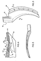
- FIG. 2 shows a reengineered airfoil 60 which may be based upon the exemplary airfoil 20.
- the airfoil 60 has a relatively gently transitioning junction 62 between a trailing feed passageway/cavity 64 and an outlet slot 66.
- a leading portion 68 of the slot 66 has a downstream-tapering thickness profile which tends to reduce the peak thickness of the pressure and suction side walls 70 and 72 (thereby reducing part mass, improving part cooling, and reducing resistance to the cooling airflow).
- Similar smooth transitions have been attempted with purely ceramic cores. However, such purely ceramic cores then suffer breakage problems if fine features of the outlet slot are to be cast.
- FIG. 3 shows a portion of a core assembly 80 for casting the passageways 64 and 66 of FIG. 2.
- the core 80 includes a ceramic core element/portion 82 and a refractory metal core (RMC) element/portion 84 (also shown in broken lines in FIG. 2). For purposes of illustration, remaining portions of the ceramic core element 82 are not shown. Additionally, apertures within both of the elements 82 and 84 are also not shown.
- RMC refractory metal core
- FIG. 4 shows the RMC 84 as including a leading tenon 90 received within a trailing slot or mortise 92 of the ceramic core element 82.
- the exemplary tenon and slot are flat with parallel surfaces respectively facing pressure and suction sides of the airfoil.
- the RMC 84 expands outward with a pair of shoulders 94 and 96 engaging trailing face portions 98 and 100 of the ceramic core element 82.
- These mating faces extend outward to respective suction and pressure side faces 102 and 104 of the core assembly 80.
- the side faces 102 and 104 smoothly transition between the ceramic core element 82 and the RMC 84. This junction between RMC and ceramic core falls along a tapering portion 106.
- the RMC transitions to a straight flat portion 108 and then to a thicker portion 110 wherein the pressure side face 104 protrudes.
- the exemplary suction side face 102 is smooth along the tapering portion, flat portion, and thicker portion 110.
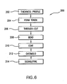
- the RMC 84 may be machined from a strip (FIG. 7) having a thickness T, a greater width W, and a yet greater length.
- gross thickness features may be machined 202 to provide the smooth transition.
- FIG. 8 shows a machining from a pressure side face 120 to define the tapering region 106 and the straight region 108.
- the tenon 90 (FIG. 9) is then formed by machining material 204 from both the pressure side face 120 and the suction side face 122.
- the steps 202 and 204 may easily be combined or further divided.
- a series of through-cuts are cut 206.
- a first group of through-cuts includes recesses 140 (FIG. 10) extending downstream through the tenon 90 and well into the trailing portion 110. Others of the cuts define apertures 141, 142, and 143 for forming posts 150, 152, and 153 (FIG. 2) within the outlet slot and apertures 144 for forming trailing dividing walls 154 along the slot outlet.
- the RMC is bent 208 to partially close the recesses 140 (FIG. 11).
- the RMC may be coated 210 with a protective coating. Alternatively a coating could be applied pre-assembly.
- Suitable coating materials include silica, alumina, zirconia, chromia, mullite and hafnia.
- CTE coefficient of thermal expansion
- Coatings may be applied by any appropriate line-of sight or non-line-of sight technique (e.g., chemical or physical vapor deposition (CVD, PVD) methods, plasma spray methods, electrophoresis, and sol gel methods).
- Individual layers may typically be 0.1 to 1 mil (0.0025 to 0.025 mm) thick.
- Layers of Pt, other noble metals, Cr, Si, W, and/or Al, or other non-metallic materials may be applied to the metallic core elements for oxidation protection in combination with a ceramic coating for protection from molten metal erosion and dissolution.
- the RMC may be assembled in a die and the ceramic core (e.g., silica-, zircon-, or alumina-based) molded thereover.
- An exemplary overmolding 212 includes molding the ceramic core 82 over the tenon 90.
- the as-molded ceramic material may include a binder.
- the binder may function to maintain integrity of the molded ceramic material in an unfired green state.
- Exemplary binders are wax-based.
- the preliminary core assembly may be debindered/fired 214 to harden the ceramic (e.g., by heating in an inert atmosphere or vacuum).
- FIG. 12 shows an exemplary method 220 for investment casting using the core assembly.
- Other methods are possible, including a variety of prior art methods and yet-developed methods.
- the fired core assembly is then overmolded 230 with an easily sacrificed material such as a natural or synthetic wax (e.g., via placing the assembly in a mold and molding the wax around it). There may be multiple such assemblies involved in a given mold.
- the overmolded core assembly (or group of assemblies) forms a casting pattern with an exterior shape largely corresponding to the exterior shape of the part to be cast.
- the pattern may then be assembled 232 to a shelling fixture (e.g., via wax welding between end plates of the fixture).
- the pattern may then be shelled 234 (e.g., via one or more stages of slurry dipping, slurry spraying, or the like).
- the drying provides the shell with at least sufficient strength or other physical integrity properties to permit subsequent processing.
- the shell containing the invested core assembly may be disassembled 238 fully or partially from the shelling fixture and then transferred 240 to a dewaxer (e.g., a steam autoclave).
- a dewaxer e.g., a steam autoclave
- a steam dewax process 242 removes a major portion of the wax leaving the core assembly secured within the shell.
- the shell and core assembly will largely form the ultimate mold.
- the dewax process typically leaves a wax or byproduct hydrocarbon residue on the shell interior and core assembly.
- the shell is transferred 244 to a furnace (e.g., containing air or other oxidizing atmosphere) in which it is heated 246 to strengthen the shell and remove any remaining wax residue (e.g., by vaporization) and/or converting hydrocarbon residue to carbon.
- Oxygen in the atmosphere reacts with the carbon to form carbon dioxide. Removal of the carbon is advantageous to reduce or eliminate the formation of detrimental carbides in the metal casting. Removing carbon offers the additional advantage of reducing the potential for clogging the vacuum pumps used in subsequent stages of operation.
- the mold may be removed from the atmospheric furnace, allowed to cool, and inspected 248.
- the mold may be seeded 250 by placing a metallic seed in the mold to establish the ultimate crystal structure of a directionally solidified (DS) casting or a single-crystal (SX) casting. Nevertheless the present teachings may be applied to other DS and SX casting techniques (e.g., wherein the shell geometry defines a grain selector) or to casting of other microstructures.
- the mold may be transferred 252 to a casting furnace (e.g., placed atop a chill plate in the furnace).
- the casting furnace may be pumped down to vacuum 254 or charged with a non-oxidizing atmosphere (e.g., inert gas) to prevent oxidation of the casting alloy.
- the casting furnace is heated 256 to preheat the mold. This preheating serves two purposes: to further harden and strengthen the shell; and to preheat the shell for the introduction of molten alloy to prevent thermal shock and premature solidification of the alloy.
- the molten alloy is poured 258 into the mold and the mold is allowed to cool to solidify 260 the alloy (e.g., after withdrawal from the furnace hot zone).
- the vacuum may be broken 262 and the chilled mold removed 264 from the casting furnace.
- the shell may be removed in a deshelling process 266 (e.g., mechanical breaking of the shell).
- the core assembly is removed in a decoring process 268 to leave a cast article (e.g., a metallic precursor of the ultimate part).
- the cast article may be machined 270, chemically and/or thermally treated 272 and coated 274 to form the ultimate part. Some or all of any machining or chemical or thermal treatment may be performed before the decoring.
- FIG. 13 shows an RMC 160 otherwise similar to the RMC 84 but wherein the apertures 141, 142, 143 and 144 are replaced by combinations of apertures 162 and wave-like slots 164.
- Each of the exemplary slots 164 includes a straight leading portion 166 through the flange, a wave-like (e.g., sinusoidal) portion 168 in the RMC tapering portion and straight region, and a terminal straight portion 170 within the thicker portion.
- the apertures 162 are interspersed between the slots 164 in phase with the waveform. In the ultimate cast airfoil, adjacent slots 164 may form dividing walls (with passageways in between including posts cast by the apertures 162).
- FIG. 14 shows an RMC 180 with similar wave-like slots 182 but lacking the apertures 162. Accordingly, the slots may be at a closer spacing than the slots 164.
- FIG. 15 shows an RMC 190 with an array of straight slots 192 in lieu of the wave-like slots 182.
- FIG. 16 shows an RMC 300 having a spanwise variation in the angle of convergence of its tapering portion 302.
- the RMC's tenon 304 and the tapering portion 302 also have as-machined spanwise curvature (e.g., as distinguished from bending at recesses).
- a trailing portion 306 is also thin and flat (as distinguished from the portion 110 of FIG 4 and, effectively a continuation of the portion 108). For ease of illustration, apertures are not shown.
- FIG. 17 an RMC 320 also having spanwise curvature, but wherein the trailing portion 302 has a spanwise variation in thickness (e.g., thicker midspan and tapering toward the inboard and outboard ends). For ease of illustration, apertures are not shown.
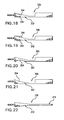
- FIG. 18 shows an RMC 330 otherwise similar to the RMC 84 but wherein the tapering portion 332 has arrays of dimple-like blind recesses 334 along the pressure and suction side faces.
- the recesses may be chemically etched, mechanically drilled, laser drilled, or the like.
- FIG. 19 shows an RMC 340 otherwise similar to the RMC 84 but wherein the tapering portion 342 has arrays of protrusions 344 along the pressure and suction side faces.
- the protrusions may be formed by welding or cladding or may be left after an etching, mechanical machining, laser drilling, EDM, or the like.
- FIG. 20 shows an RMC 350 otherwise similar to the RMC 84 but wherein the tapering portion 352 has a streamwise concavity extending 354 along the suction side face.
- the concavity may be formed in the initial machining.
- FIG. 21 shows an RMC 360 otherwise similar to the RMC 84 but wherein the tapering portion 362 has a streamwise concavity extending 364 along the pressure side face.
- the concavity may be formed in the initial machining
- FIG. 22 shows an RMC 370 otherwise similar to the RMC 84 but wherein the tapering portion 372 tapers along both the pressure and suction side faces. Also, the exemplary RMC 370 has a thin trailing portion 374 in place of the thick trailing portion 110.
Landscapes
- Engineering & Computer Science (AREA)
- Mechanical Engineering (AREA)
- Molds, Cores, And Manufacturing Methods Thereof (AREA)
- Turbine Rotor Nozzle Sealing (AREA)
Priority Applications (1)
| Application Number | Priority Date | Filing Date | Title |
|---|---|---|---|
| EP12172256.5A EP2511024B1 (de) | 2006-05-12 | 2007-05-11 | Profilierter metallener gusskern |
Applications Claiming Priority (1)
| Application Number | Priority Date | Filing Date | Title |
|---|---|---|---|
| US11/433,500 US7757745B2 (en) | 2006-05-12 | 2006-05-12 | Contoured metallic casting core |
Related Child Applications (2)
| Application Number | Title | Priority Date | Filing Date |
|---|---|---|---|
| EP12172256.5A Division EP2511024B1 (de) | 2006-05-12 | 2007-05-11 | Profilierter metallener gusskern |
| EP12172256.5A Division-Into EP2511024B1 (de) | 2006-05-12 | 2007-05-11 | Profilierter metallener gusskern |
Publications (3)
| Publication Number | Publication Date |
|---|---|
| EP1854567A2 true EP1854567A2 (de) | 2007-11-14 |
| EP1854567A3 EP1854567A3 (de) | 2010-01-13 |
| EP1854567B1 EP1854567B1 (de) | 2012-09-05 |
Family
ID=38325379
Family Applications (2)
| Application Number | Title | Priority Date | Filing Date |
|---|---|---|---|
| EP07251953A Ceased EP1854567B1 (de) | 2006-05-12 | 2007-05-11 | Profilierter metallener Gusskern |
| EP12172256.5A Ceased EP2511024B1 (de) | 2006-05-12 | 2007-05-11 | Profilierter metallener gusskern |
Family Applications After (1)
| Application Number | Title | Priority Date | Filing Date |
|---|---|---|---|
| EP12172256.5A Ceased EP2511024B1 (de) | 2006-05-12 | 2007-05-11 | Profilierter metallener gusskern |
Country Status (5)
| Country | Link |
|---|---|
| US (1) | US7757745B2 (de) |
| EP (2) | EP1854567B1 (de) |
| JP (1) | JP2007301636A (de) |
| KR (1) | KR20070109817A (de) |
| SG (1) | SG137764A1 (de) |
Cited By (9)
| Publication number | Priority date | Publication date | Assignee | Title |
|---|---|---|---|---|
| EP2141326A2 (de) * | 2008-07-03 | 2010-01-06 | United Technologies Corporation | Schaufelprofil mit kegelförmigem Radialkühlkanal |
| EP2223753A1 (de) | 2009-02-17 | 2010-09-01 | United Technologies Corporation | Verfahren und feuerfester Metallkern zur Erzeugung von Mikroschaltungen mit unterschiedlicher Dicke für Turbinenmotorkomponente |
| WO2011106131A1 (en) * | 2010-02-25 | 2011-09-01 | Siemens Energy, Inc. | Casting core for turbine engine components and method of making the same |
| EP2399693A3 (de) * | 2010-06-25 | 2012-07-25 | United Technologies Corporation | Profilierter metallener Gusskern |
| WO2013163020A1 (en) | 2012-04-24 | 2013-10-31 | United Technologies Corporation | Gas turbine engine core providing exterior airfoil portion |
| FR2991612A1 (fr) * | 2012-06-11 | 2013-12-13 | Snecma | Procede d'obtention par fonderie d'une piece comportant une portion effilee |
| EP3196416A1 (de) * | 2016-01-25 | 2017-07-26 | United Technologies Corporation | Gusskern mit variabler dicke für eine gasturbinenkomponente |
| EP3246533A1 (de) * | 2016-05-18 | 2017-11-22 | United Technologies Corporation | Geformte kühlkanäle für aussendichtung für eine turbinenschaufel |
| EP3590627A1 (de) * | 2013-11-11 | 2020-01-08 | United Technologies Corporation | Verfahren zur endbearbeitung eines hochschmelzenden metallkerns |
Families Citing this family (20)
| Publication number | Priority date | Publication date | Assignee | Title |
|---|---|---|---|---|
| US7950441B2 (en) * | 2007-07-20 | 2011-05-31 | GM Global Technology Operations LLC | Method of casting damped part with insert |
| US9403208B2 (en) | 2010-12-30 | 2016-08-02 | United Technologies Corporation | Method and casting core for forming a landing for welding a baffle inserted in an airfoil |
| US8602845B2 (en) | 2011-09-23 | 2013-12-10 | United Technologies Corporation | Strengthening by machining |
| US20130280081A1 (en) | 2012-04-24 | 2013-10-24 | Mark F. Zelesky | Gas turbine engine airfoil geometries and cores for manufacturing process |
| EP2961547A4 (de) * | 2013-03-01 | 2016-11-23 | United Technologies Corp | Herstellungsverfahren für gasturbinenmotorkomponente und kern zur herstellung davon |
| JP6537221B2 (ja) * | 2013-03-13 | 2019-07-03 | ハウメット コーポレイションHowmet Corporation | 複合インサートを有するエアフォイル鋳造用セラミックコア |
| US20160017724A1 (en) * | 2013-04-03 | 2016-01-21 | United Technologies Corporation | Variable thickness trailing edge cavity and method of making |
| US10329916B2 (en) * | 2014-05-01 | 2019-06-25 | United Technologies Corporation | Splayed tip features for gas turbine engine airfoil |
| US9579714B1 (en) | 2015-12-17 | 2017-02-28 | General Electric Company | Method and assembly for forming components having internal passages using a lattice structure |
| US10118217B2 (en) | 2015-12-17 | 2018-11-06 | General Electric Company | Method and assembly for forming components having internal passages using a jacketed core |
| US10046389B2 (en) | 2015-12-17 | 2018-08-14 | General Electric Company | Method and assembly for forming components having internal passages using a jacketed core |
| US10099283B2 (en) | 2015-12-17 | 2018-10-16 | General Electric Company | Method and assembly for forming components having an internal passage defined therein |
| US9968991B2 (en) | 2015-12-17 | 2018-05-15 | General Electric Company | Method and assembly for forming components having internal passages using a lattice structure |
| US10099284B2 (en) | 2015-12-17 | 2018-10-16 | General Electric Company | Method and assembly for forming components having a catalyzed internal passage defined therein |
| US9987677B2 (en) | 2015-12-17 | 2018-06-05 | General Electric Company | Method and assembly for forming components having internal passages using a jacketed core |
| US10137499B2 (en) | 2015-12-17 | 2018-11-27 | General Electric Company | Method and assembly for forming components having an internal passage defined therein |
| US10099276B2 (en) | 2015-12-17 | 2018-10-16 | General Electric Company | Method and assembly for forming components having an internal passage defined therein |
| US10150158B2 (en) | 2015-12-17 | 2018-12-11 | General Electric Company | Method and assembly for forming components having internal passages using a jacketed core |
| US10335853B2 (en) | 2016-04-27 | 2019-07-02 | General Electric Company | Method and assembly for forming components using a jacketed core |
| US10286450B2 (en) | 2016-04-27 | 2019-05-14 | General Electric Company | Method and assembly for forming components using a jacketed core |
Citations (4)
| Publication number | Priority date | Publication date | Assignee | Title |
|---|---|---|---|---|
| US6637500B2 (en) | 2001-10-24 | 2003-10-28 | United Technologies Corporation | Cores for use in precision investment casting |
| EP1467065A2 (de) | 2003-04-08 | 2004-10-13 | United Technologies Corporation | Turbinenschaufel |
| US6929054B2 (en) | 2003-12-19 | 2005-08-16 | United Technologies Corporation | Investment casting cores |
| EP1652603A2 (de) | 2004-10-29 | 2006-05-03 | United Technologies Corporation | Kerne für das Feingiessen und Verfahren |
Family Cites Families (1)
| Publication number | Priority date | Publication date | Assignee | Title |
|---|---|---|---|---|
| US7334625B2 (en) * | 2005-09-19 | 2008-02-26 | United Technologies Corporation | Manufacture of casting cores |
-
2006
- 2006-05-12 US US11/433,500 patent/US7757745B2/en active Active
-
2007
- 2007-04-11 KR KR1020070035413A patent/KR20070109817A/ko not_active Ceased
- 2007-05-02 JP JP2007121357A patent/JP2007301636A/ja active Pending
- 2007-05-08 SG SG200703310-3A patent/SG137764A1/en unknown
- 2007-05-11 EP EP07251953A patent/EP1854567B1/de not_active Ceased
- 2007-05-11 EP EP12172256.5A patent/EP2511024B1/de not_active Ceased
Patent Citations (4)
| Publication number | Priority date | Publication date | Assignee | Title |
|---|---|---|---|---|
| US6637500B2 (en) | 2001-10-24 | 2003-10-28 | United Technologies Corporation | Cores for use in precision investment casting |
| EP1467065A2 (de) | 2003-04-08 | 2004-10-13 | United Technologies Corporation | Turbinenschaufel |
| US6929054B2 (en) | 2003-12-19 | 2005-08-16 | United Technologies Corporation | Investment casting cores |
| EP1652603A2 (de) | 2004-10-29 | 2006-05-03 | United Technologies Corporation | Kerne für das Feingiessen und Verfahren |
Cited By (18)
| Publication number | Priority date | Publication date | Assignee | Title |
|---|---|---|---|---|
| EP2141326A2 (de) * | 2008-07-03 | 2010-01-06 | United Technologies Corporation | Schaufelprofil mit kegelförmigem Radialkühlkanal |
| US9038700B2 (en) | 2009-02-17 | 2015-05-26 | United Technologies Corporation | Process and refractory metal core for creating varying thickness microcircuits for turbine engine components |
| EP2223753A1 (de) | 2009-02-17 | 2010-09-01 | United Technologies Corporation | Verfahren und feuerfester Metallkern zur Erzeugung von Mikroschaltungen mit unterschiedlicher Dicke für Turbinenmotorkomponente |
| US8347947B2 (en) | 2009-02-17 | 2013-01-08 | United Technologies Corporation | Process and refractory metal core for creating varying thickness microcircuits for turbine engine components |
| EP2223753B1 (de) * | 2009-02-17 | 2016-07-06 | United Technologies Corporation | Verfahren und feuerfester Metallkern zur Erzeugung von Mikroschaltungen mit unterschiedlicher Dicke für Turbinenmotorkomponente |
| WO2011106131A1 (en) * | 2010-02-25 | 2011-09-01 | Siemens Energy, Inc. | Casting core for turbine engine components and method of making the same |
| EP2399693A3 (de) * | 2010-06-25 | 2012-07-25 | United Technologies Corporation | Profilierter metallener Gusskern |
| EP2841710A4 (de) * | 2012-04-24 | 2016-03-09 | United Technologies Corp | Gasturbinenmotorkern mit einem äusseren schaufelblattteil |
| WO2013163020A1 (en) | 2012-04-24 | 2013-10-31 | United Technologies Corporation | Gas turbine engine core providing exterior airfoil portion |
| EP2841710B1 (de) | 2012-04-24 | 2018-10-31 | United Technologies Corporation | Gasturbinenmotorkern mit einem äusseren schaufelblattteil |
| FR2991612A1 (fr) * | 2012-06-11 | 2013-12-13 | Snecma | Procede d'obtention par fonderie d'une piece comportant une portion effilee |
| GB2504833B (en) * | 2012-06-11 | 2016-03-30 | Snecma | A casting method for obtaining a part including a slender portion |
| US9962763B2 (en) | 2012-06-11 | 2018-05-08 | Snecma | Casting method for obtaining a part including a tapering portion |
| EP3590627A1 (de) * | 2013-11-11 | 2020-01-08 | United Technologies Corporation | Verfahren zur endbearbeitung eines hochschmelzenden metallkerns |
| US10744557B2 (en) | 2013-11-11 | 2020-08-18 | Raytheon Technologies Corporation | Refractory metal core finishing technique |
| EP3196416A1 (de) * | 2016-01-25 | 2017-07-26 | United Technologies Corporation | Gusskern mit variabler dicke für eine gasturbinenkomponente |
| EP3246533A1 (de) * | 2016-05-18 | 2017-11-22 | United Technologies Corporation | Geformte kühlkanäle für aussendichtung für eine turbinenschaufel |
| US11193386B2 (en) | 2016-05-18 | 2021-12-07 | Raytheon Technologies Corporation | Shaped cooling passages for turbine blade outer air seal |
Also Published As
| Publication number | Publication date |
|---|---|
| EP1854567A3 (de) | 2010-01-13 |
| KR20070109817A (ko) | 2007-11-15 |
| EP2511024B1 (de) | 2019-01-09 |
| JP2007301636A (ja) | 2007-11-22 |
| EP2511024A2 (de) | 2012-10-17 |
| EP1854567B1 (de) | 2012-09-05 |
| US20070261814A1 (en) | 2007-11-15 |
| EP2511024A3 (de) | 2014-04-02 |
| US7757745B2 (en) | 2010-07-20 |
| SG137764A1 (en) | 2007-12-28 |
Similar Documents
| Publication | Publication Date | Title |
|---|---|---|
| EP2511024B1 (de) | Profilierter metallener gusskern | |
| EP1914030B1 (de) | Feingusskerne und deren Anwendung beim Feingiessen | |
| EP2191911B1 (de) | Präzisionsgusskerne und Verfahren | |
| EP1857199B1 (de) | Feingusskernanordnung | |
| US8137068B2 (en) | Castings, casting cores, and methods | |
| EP1992431B1 (de) | Präzisionsgusskerne und Verfahren | |
| US8251123B2 (en) | Casting core assembly methods | |
| US8171978B2 (en) | Castings, casting cores, and methods | |
| US8113780B2 (en) | Castings, casting cores, and methods | |
| EP2335845A1 (de) | Formlinge, Gusskerne und Verfahren | |
| EP2399693B1 (de) | Profilierter metallener Gusskern |
Legal Events
| Date | Code | Title | Description |
|---|---|---|---|
| PUAI | Public reference made under article 153(3) epc to a published international application that has entered the european phase |
Free format text: ORIGINAL CODE: 0009012 |
|
| AK | Designated contracting states |
Kind code of ref document: A2 Designated state(s): AT BE BG CH CY CZ DE DK EE ES FI FR GB GR HU IE IS IT LI LT LU LV MC MT NL PL PT RO SE SI SK TR |
|
| AX | Request for extension of the european patent |
Extension state: AL BA HR MK YU |
|
| PUAL | Search report despatched |
Free format text: ORIGINAL CODE: 0009013 |
|
| AK | Designated contracting states |
Kind code of ref document: A3 Designated state(s): AT BE BG CH CY CZ DE DK EE ES FI FR GB GR HU IE IS IT LI LT LU LV MC MT NL PL PT RO SE SI SK TR |
|
| AX | Request for extension of the european patent |
Extension state: AL BA HR MK RS |
|
| 17P | Request for examination filed |
Effective date: 20100709 |
|
| 17Q | First examination report despatched |
Effective date: 20100806 |
|
| AKX | Designation fees paid |
Designated state(s): DE GB |
|
| GRAP | Despatch of communication of intention to grant a patent |
Free format text: ORIGINAL CODE: EPIDOSNIGR1 |
|
| GRAS | Grant fee paid |
Free format text: ORIGINAL CODE: EPIDOSNIGR3 |
|
| GRAA | (expected) grant |
Free format text: ORIGINAL CODE: 0009210 |
|
| AK | Designated contracting states |
Kind code of ref document: B1 Designated state(s): DE GB |
|
| REG | Reference to a national code |
Ref country code: GB Ref legal event code: FG4D Ref country code: DE Ref legal event code: R081 Ref document number: 602007025251 Country of ref document: DE Owner name: UNITED TECHNOLOGIES CORP. (N.D.GES.D. STAATES , US Free format text: FORMER OWNER: UNITED TECHNOLOGIES INC., HARTFORD, CONN., US |
|
| REG | Reference to a national code |
Ref country code: DE Ref legal event code: R096 Ref document number: 602007025251 Country of ref document: DE Effective date: 20121031 |
|
| PLBE | No opposition filed within time limit |
Free format text: ORIGINAL CODE: 0009261 |
|
| STAA | Information on the status of an ep patent application or granted ep patent |
Free format text: STATUS: NO OPPOSITION FILED WITHIN TIME LIMIT |
|
| 26N | No opposition filed |
Effective date: 20130606 |
|
| REG | Reference to a national code |
Ref country code: DE Ref legal event code: R097 Ref document number: 602007025251 Country of ref document: DE Effective date: 20130606 |
|
| REG | Reference to a national code |
Ref country code: DE Ref legal event code: R082 Ref document number: 602007025251 Country of ref document: DE Representative=s name: SCHMITT-NILSON SCHRAUD WAIBEL WOHLFROM PATENTA, DE |
|
| REG | Reference to a national code |
Ref country code: DE Ref legal event code: R082 Ref document number: 602007025251 Country of ref document: DE Representative=s name: SCHMITT-NILSON SCHRAUD WAIBEL WOHLFROM PATENTA, DE Ref country code: DE Ref legal event code: R081 Ref document number: 602007025251 Country of ref document: DE Owner name: UNITED TECHNOLOGIES CORP. (N.D.GES.D. STAATES , US Free format text: FORMER OWNER: UNITED TECHNOLOGIES CORPORATION, HARTFORD, CONN., US |
|
| REG | Reference to a national code |
Ref country code: DE Ref legal event code: R081 Ref document number: 602007025251 Country of ref document: DE Owner name: RAYTHEON TECHNOLOGIES CORPORATION (N.D.GES.D.S, US Free format text: FORMER OWNER: UNITED TECHNOLOGIES CORP. (N.D.GES.D. STAATES DELAWARE), FARMINGTON, CONN., US |
|
| P01 | Opt-out of the competence of the unified patent court (upc) registered |
Effective date: 20230519 |
|
| PGFP | Annual fee paid to national office [announced via postgrant information from national office to epo] |
Ref country code: DE Payment date: 20230419 Year of fee payment: 17 |
|
| PGFP | Annual fee paid to national office [announced via postgrant information from national office to epo] |
Ref country code: GB Payment date: 20230420 Year of fee payment: 17 |
|
| REG | Reference to a national code |
Ref country code: DE Ref legal event code: R119 Ref document number: 602007025251 Country of ref document: DE |
|
| GBPC | Gb: european patent ceased through non-payment of renewal fee |
Effective date: 20240511 |
|
| PG25 | Lapsed in a contracting state [announced via postgrant information from national office to epo] |
Ref country code: DE Free format text: LAPSE BECAUSE OF NON-PAYMENT OF DUE FEES Effective date: 20241203 |
|
| PG25 | Lapsed in a contracting state [announced via postgrant information from national office to epo] |
Ref country code: GB Free format text: LAPSE BECAUSE OF NON-PAYMENT OF DUE FEES Effective date: 20240511 |